

Page 1

ELECTRONIC ENGINEERING LTD
.
Serenity™
CONTROL PANEL
Technician’s
Handbook
Note: this is a draft version
Page 2

SERENITY – technician Guide
2
IMPORTANT NOTICE
All information and data contained in this document is proprietary and confidential. CROW Electronic Engineering Ltd.
shall not be liable, in any event, for any claims for damages or any other remedy in any jurisd ic tio n wh atsoev er, wh ether
in an action in contract, tort (inc luding negligence and strict liabi lity) or any other theory of liab ility, whether in law or
equity including, without limitation, claims for damages or any other remedy in whatever jurisdiction, and shall not
assume responsibility for patent infringem ents or other rights to third parties, arising out of or in co nnection with this
document.
Further, CROW Electronic Engineering Ltd. reserves the right to revise this publication and to make changes to its
content, at any time, without obliga tion to notify any person or entity of such revision changes. These ma terials are
copyrighted and any unauthorized use of these materials may violate copyright, trademark, and other laws. Th erefore,
no part of this publication may be reproduced, photocopied, stored on a retrieval system, or transmitted without the
express written consent of CROW Electronic Engineering Ltd. Any new issu e of this document invalidates previous issues.
©CROW Electronic Engineering Ltd. 2005. All rights reserved.
Information in this document is subject to change without notice. No part of this document may be reproduced or
transmitted in any form or by any means, electronic or mechanical, without express written permission of CROW
Electronic Engineering Ltd..
P/N Feb 2014
Page 3

3
Technician Handbook content
SERENITY Installation Guide
Installation Instructions…………….. …………………………………………………………….4
How to use this handbook
Touch Panel structure description …………………………………………………………….8
Keypad Function + Alphanumeric Keys……………………………………………………..9
Table 1: Keypad keys description…………………………………………………………….…9
Table 2: Main screen buttons and symbols description …………………...………10
Table 3: Alarm/Trouble Graphic Symbols………………………………………….……….11
Using Keypad Helpful Tips…………………………………………………………….……….…..13
Control Panel Programming Types
Local Configuration Mode…………………………………………………………………….…….15
Quick Programming Mode ……………………………………………………………………..….17
Installer Program Mode….………………………………………………………………………....20
User Programming Mode….……….……………………………………………………………….21
End User Permissions Programming…………………………………………………………..21
Serenity Quick Programming Guide
Quick programming recommended steps list ……………………………………….….23
Setting of Zone Configuration
………………………………………………………………………..…………………………………….…….27
Installation summary tables
All program addresses list …………………………………………………………………….…...29
Page 4
SERENITY – technician Guide
4
SERENITY Installation Guide
This Installation manual is a part of manuals set. Please refer to technician manual for
configuration of the panel.
1. Warnings
This product is designed for indoor use only. Read carefully all manuals before
installing the product.
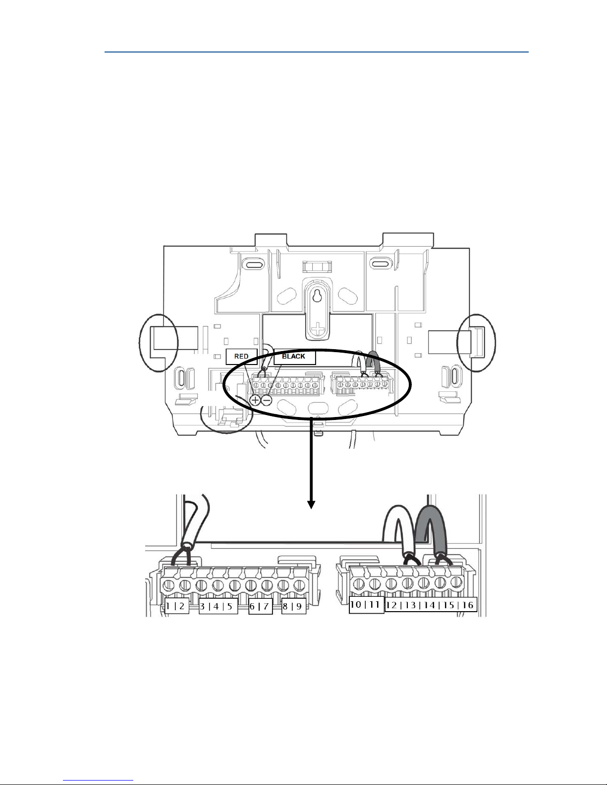
2. Connection Diagram
Page 5
5
3. Connection Diagram
1
Connect the RED wire of
the power adapter
(supplied)
2
Connect the BLACK
wire of the power
adapter (supplied)
3 Zone 31 wire connection
4
Common connection for
wired Zone 31 & Zone
32
5 Zone 32 wire connection
6
Wire connection for
"Output 3"
7
Wire connection for
"Output 2"
8
Positive 12V voltage
output (for external
devices)
9
Negative 12V voltage
output (for external
devices)
10
"High" CAN BUS
connector
11
"Low" CAN BUS
connector
12 Ground connection
13
14
Phone Line IN.
15
16
Phone Line OUT
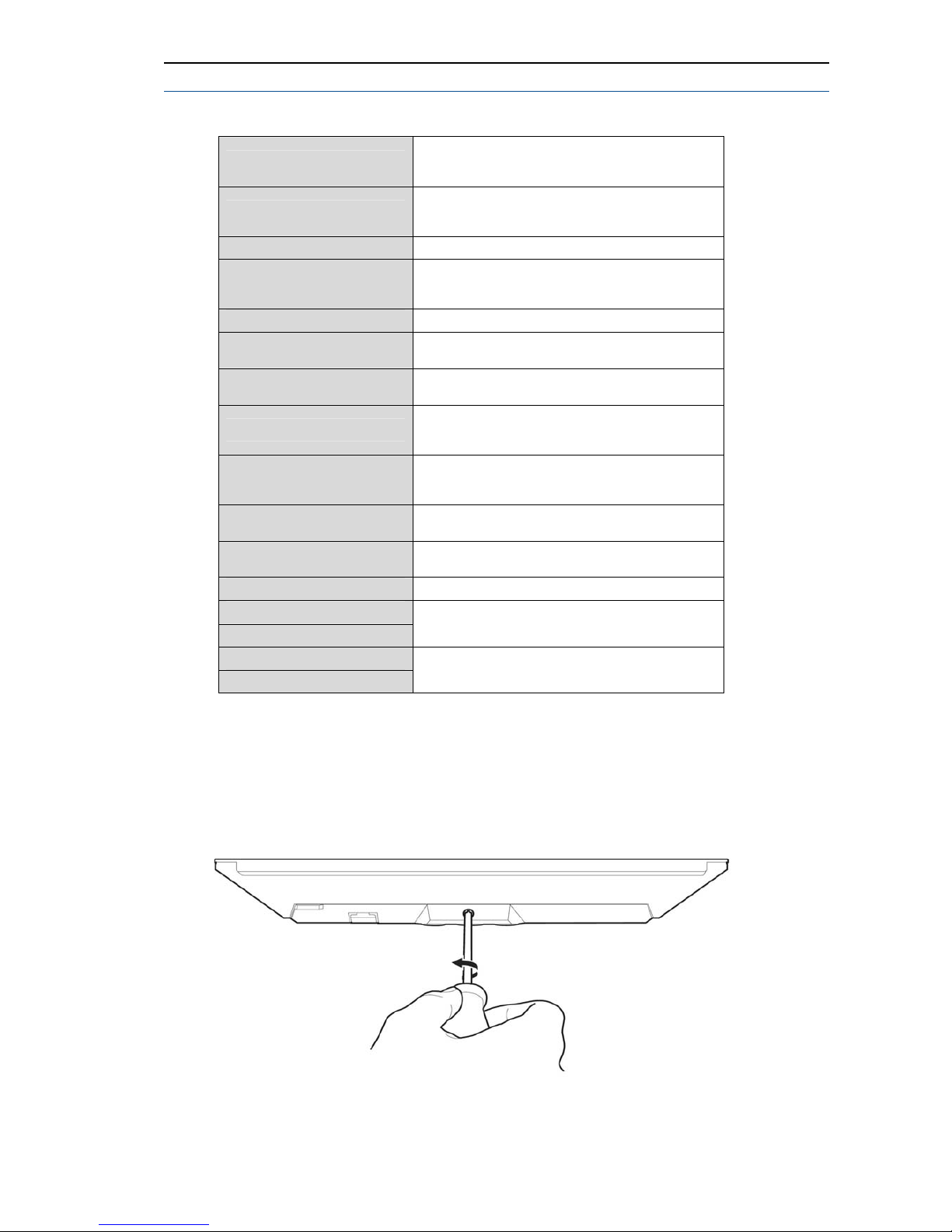
4. Panel Mounting
Unscrew the bracket from the panel
Page 6
SERENITY – technician Guide
6
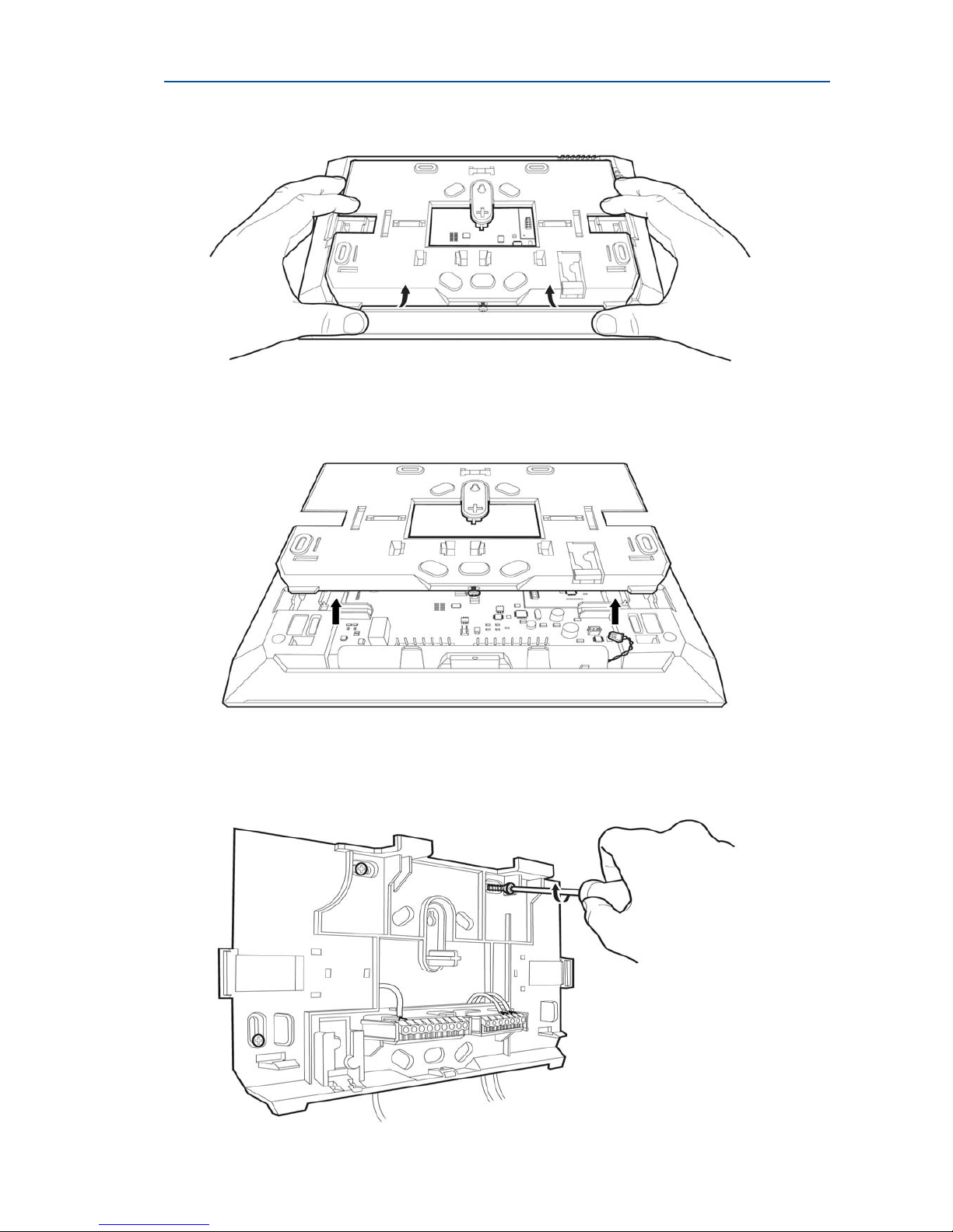
Lift the two notches located on the both sides of the bracket
Remove the bracket from the panel
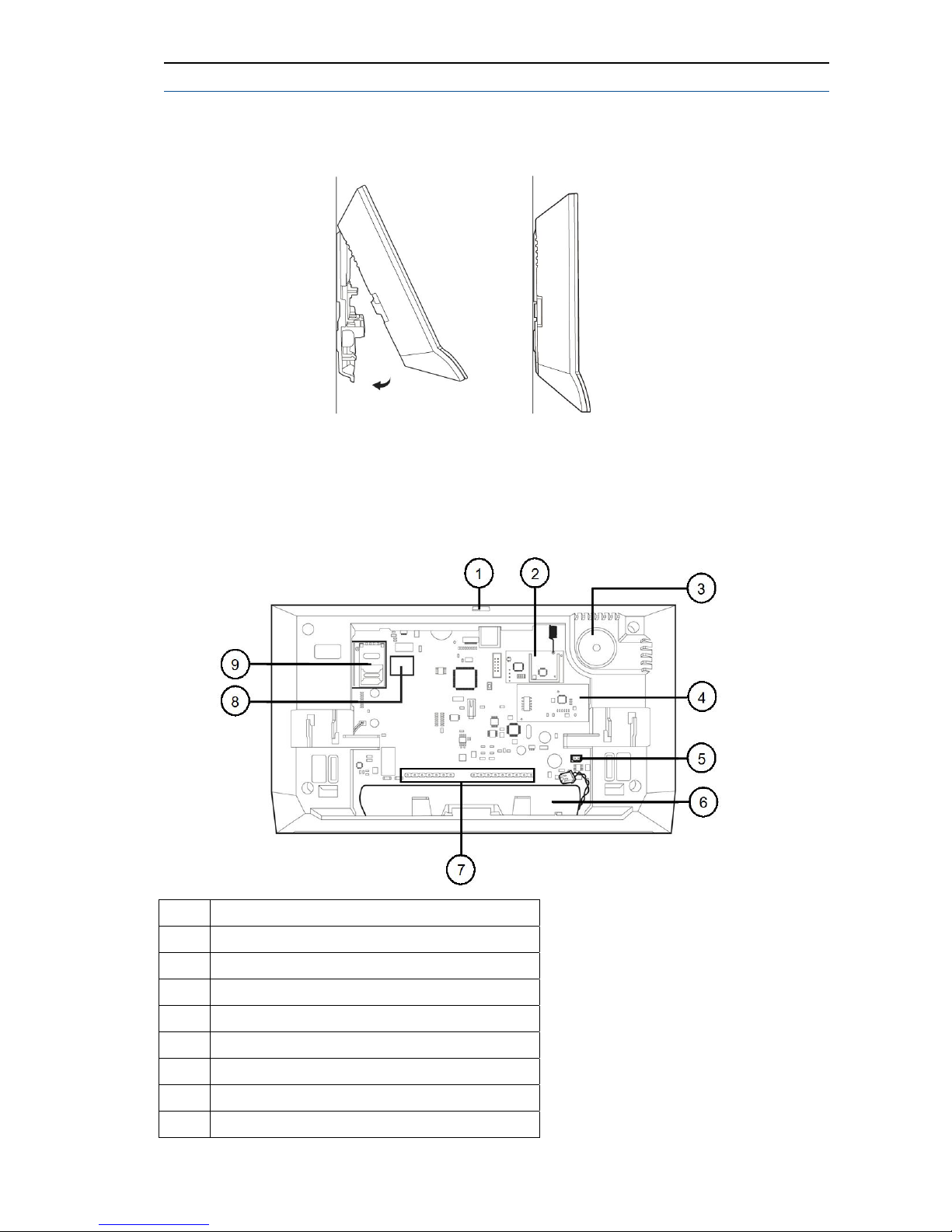
Connect wires into terminal blocks according configuration requirements (see
"Connection Diagram") and screw the bracket on the wall.
Page 7
7
Once all connections are made, connect the battery and mount the panel on its
bracket.
Screw the bracket to the panel.
4. Rear View
1 USB Port (USB cable supplied)
2 Wireless Radio Module
3 Internal Piezo Sounder
4 RFID Module
5 Battery Connector
6 NI-MH battery Back-up (supplied)
7 Wires connection
8 Ethernet Port (RJ45 cable supplied)
9 GSM/GPRS Module (SIM card not included)
Page 8
SERENITY – technician Guide
8
How to Use this Handbook
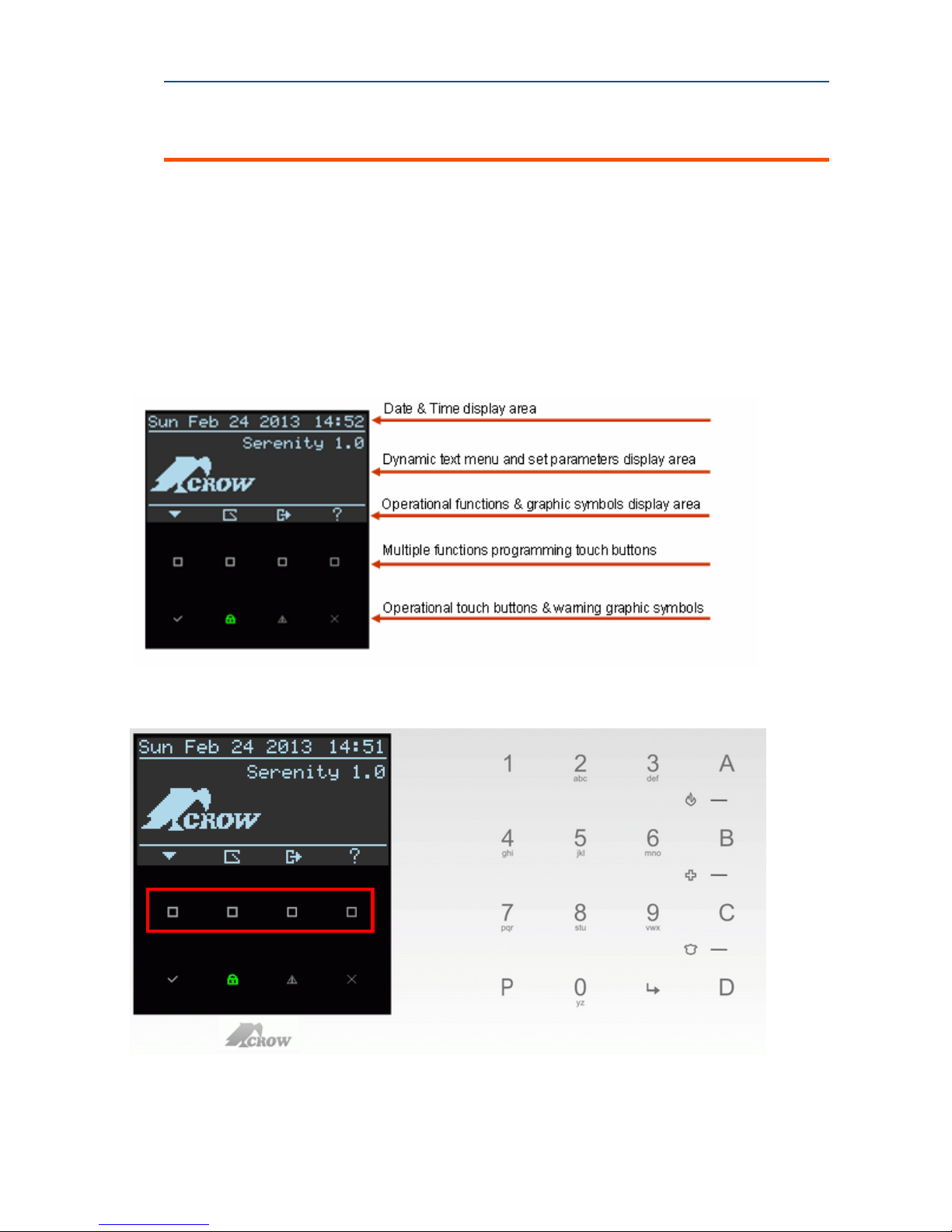
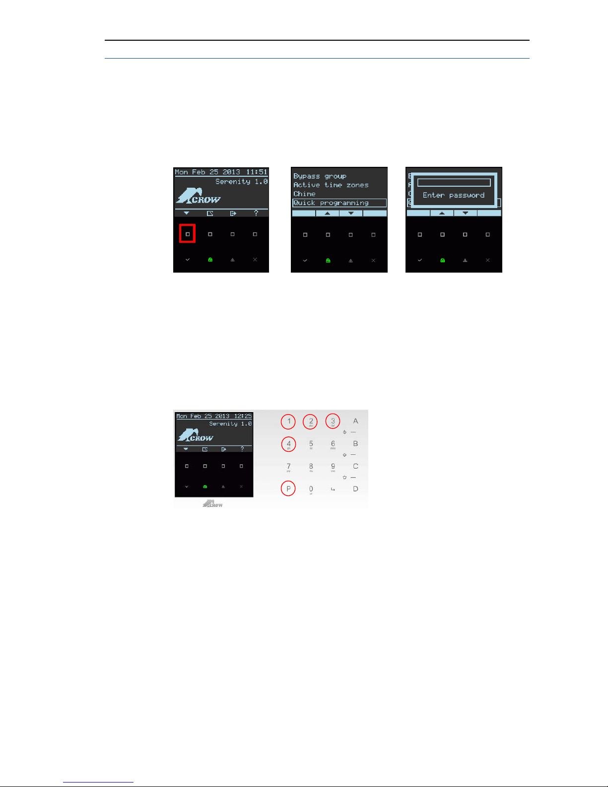
The following program summary is an abridged version of the Installation Guide, describing
the panel program definitions and command addresses. It is intended as a quick guide for
finding a program address and entering parameters rapidly. Enter the installer programming
mode by using the keypad numerical keys, or by the main menu Display, using the touch
panel buttons, and select from the drop list the required programming mode, then use the
buttons on the touch panel screen (see picture 1 & picture 2) to search the required menu,
and to define the system's parameters. The program addresses are in numerical order,
making them easy to find.
Integrated touch panel structure description
Picture 1
Picture 2
Example 1: Main display Buttons/symbols and Keypad keys (see table 1 & table 2)
Important Note:
Multiple programming function touch buttons (above marked in red) change
functionality according to menu level. Functionali ties are displayed on status symbols display area .
Page 9
9
Keypad Function + Alphanumeric Keys
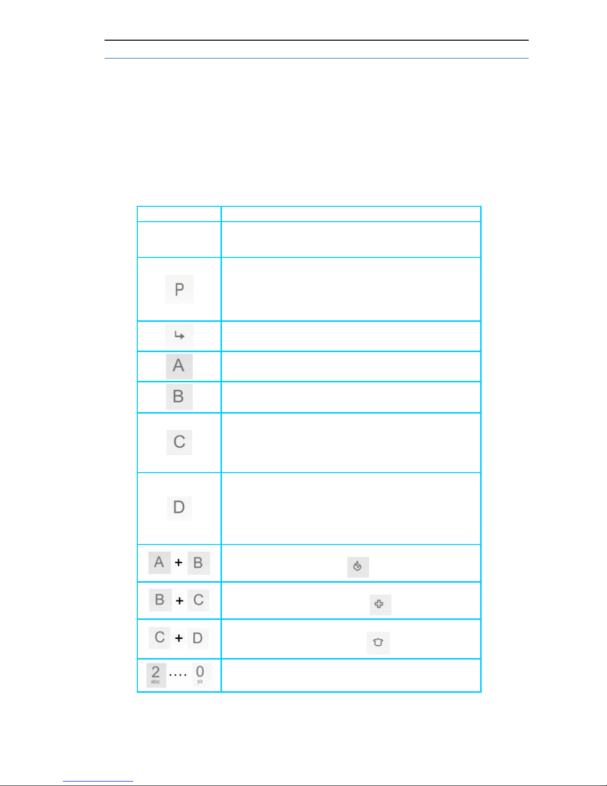
These keys are used to arm the system, enter commands to alter system settings,
view status events, scroll through the history events and mo re.
In addition the keys are used to enter codes, initiate Emergency and used for
programming. Please review the next 2 tables table 1 and table 2.
Table 1: Keypad Keys Description
Keys Description
1,2,3….0
Used for insertion of numbers or letters, key no.1 can be
also used for creation actions such as <space >, (+)and
(,)
The P key is used for:
1. Entering programming mode (e.g. P000000E)
2. Dot (.) symbol
3. Entering a command address (e.g. P1E )
P=program E=ENTER
ENTER key
The A key-used for ARM - pre-programmed
The B key-used for zone bypass action - pre-programmed
1.The C key-used to enter to memory display – pre-
programmed
2. Can be used to check all boxes for specific parameter
by one press.
1. The D key-used to switch chime on/off- preprogrammed.
2.Delete input, and deselects all boxes in an open
parameter by one
press.
A "Fire" alarm will be generated if "A" & "B" keypad keys
are pressed simultaneously
A "Medical" alarm will be generated if "B" & "C" keypad
keys are pressed simultaneously
A "Panic" alarm will be generated if "C" & "D" keypad
keys are pressed simultaneously
The A...B...C…Z letters used for editing names and words
NOTE: A, B, C and D are programmable keys, (see command address P114). Ca n be
programmed by entering P000000E and entering P114E or from main menu
programming Keypads function buttons
Page 10
SERENITY – technician Guide
10
NOTE: See page 09 for helpful tips and examples on how to use the keypad to quickly select
specific number from multiple choices such as zones, outputs, users and more.
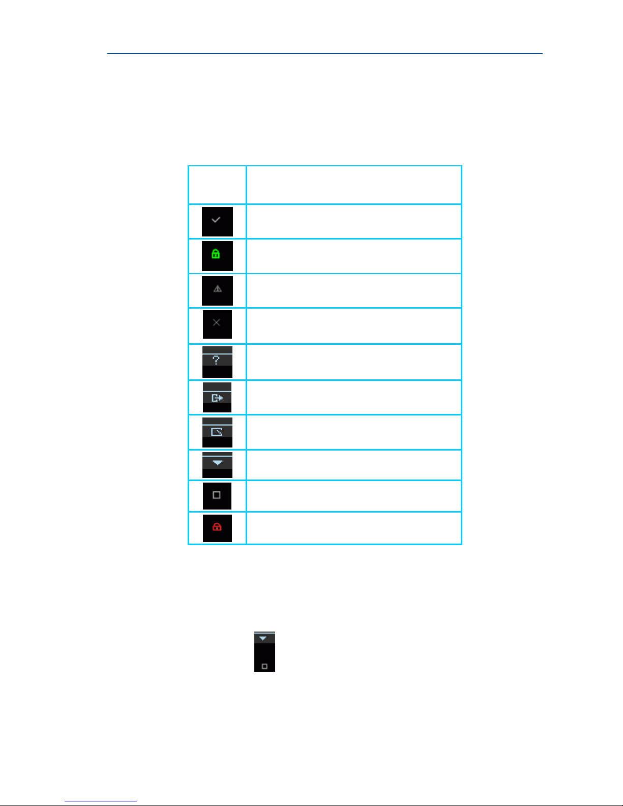
Table 2: Main Screen Buttons & Symbols
Description
Button/
Graphic
indication
Description
ENTER and save action touch button
ARM OR DISARM Touch Button and Disarm
status indication light.
Alarm/troubles status display Touch Button ,
and Warning alert indication
ESC or EXIT touch button
View of A,B,C, and D keys function
Output Control function and status view
View Open Zones
Main Menu List
Executable Touch button
ARM/Disarm status indication light
Important Note: The <Lock> and <A> keys can DISARM only during Exit Delay.
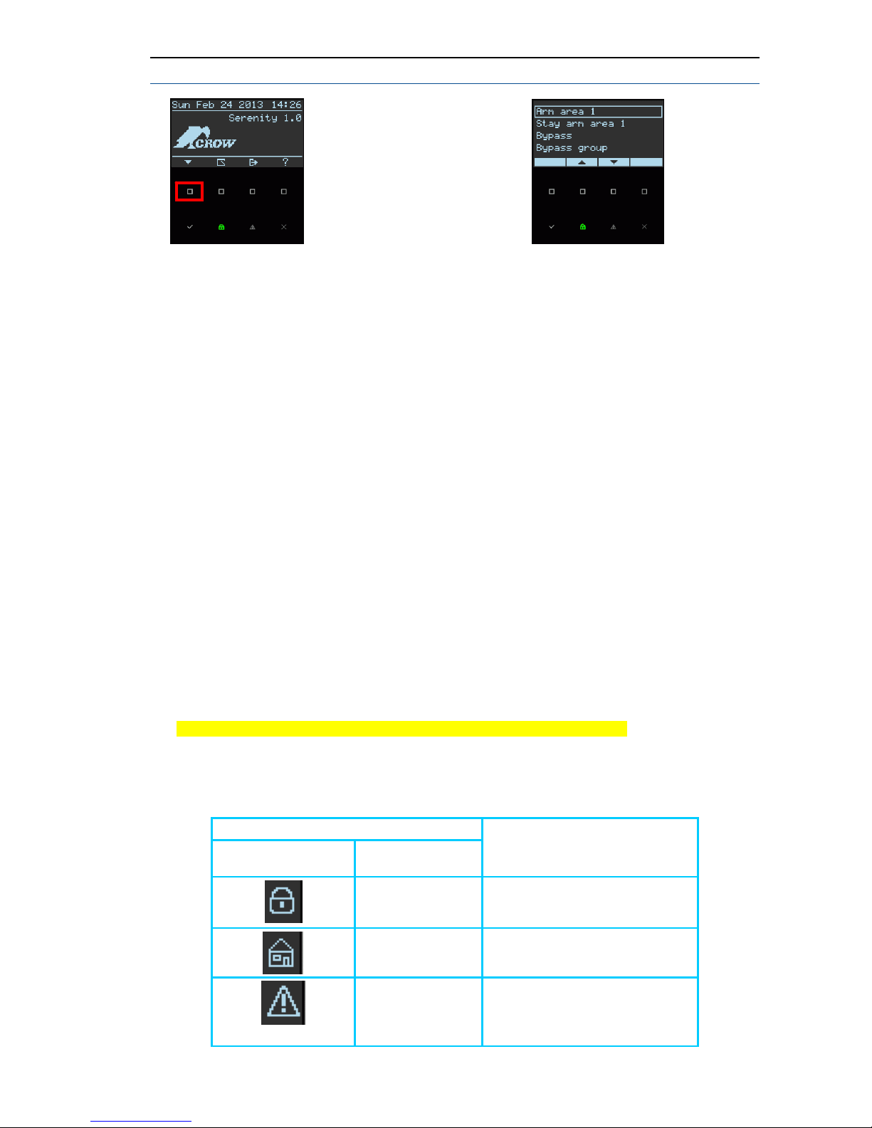
Control Main Menu Commands
Press on the Main Menu Button
and review all control main menu levels
Page 11
11
By default the control menu has the following commands list:
-Arm area 1
- Stay arm area 1
- Bypass
- Bypass group
- Active time zones
- Chime
- Quick Programming
-Local configuration
-Memory
-Dial phone number
-Voice mail.
Customizing the Main Menu Level List
The installer allows customizing the control menu commands list and adapting its commands
and behaviour to the requirements of the particular user per each keypad.
In order to perform the commands customization list, insta ller has two options:
1. Programming Mode --> Keypads --> Control Menu (see on page 12, how to
access to programming mode )
2. Using command Address P113E (see descr ip tion in installation summary tables
chapter in this guide).
Important Note: Voice mail message record time is 2 Min. total
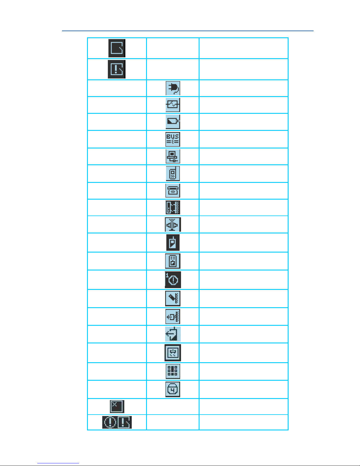
Table 3: Alarm/Trouble Graphic Symbols
Alarm Symbols Display
Main Display
screen
Alarm Status
view screen
Description
Flashing Symbol–Exit delay
Time Stable Symbol- AREA is
in ARM state
AREA is in STAY Armed state
Flashing Symbol – indicates
Critical Alarm
Stable Symbol - indicates
Trouble alarm
Page 12
SERENITY – technician Guide
12
Open Zone
Zone Tamper Open or Low
Battery or zone sensor-watch
Main Power Fail
Fuse Fail
Low Battery (panel)
CAN BUS Fail
Ethernet Fail
GSM/GPRS Fail
Communication Fail
Panel Tamper
RF Jamming
Radio Zones Low Battery
Pendant low battery
AREA is not ready – the number
1 indicates AREA number 1
Zone Tamper
Output Tamper
Output Low Battery
Output Monitor Fail
Ten code attempts
Area 4 Armed
Zone Bypass
Alarm in Arm Mode
Page 13
13
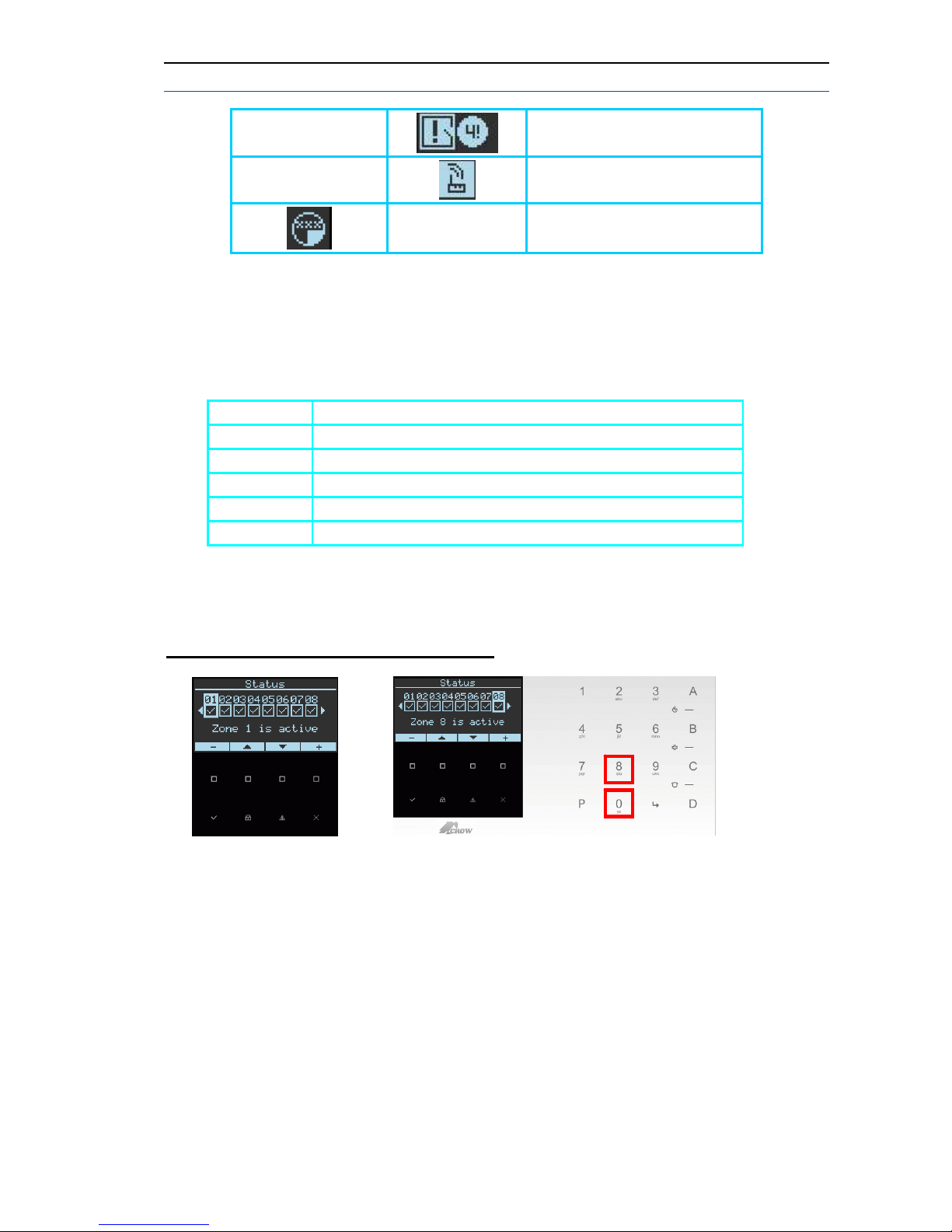
EX. Open Zone in Area 4
Zone Missing
Time Zone Password active
Indication
Audible Signals
When the keypad is used to activate or deactivate the different functions it emits
different audible beeps. Their meaning is described in the table 3.
Table 4: List of Audible Signals
Sound Description
Short beep When a key in the keypad has been pressed.
Triple beeps For ARM/DISARM/WARNING/STAY operations.
Long beep For alarms/warning corresponded configuration parameters.
Slow beeping At arming(start exit delay) and warning (entry delay)
Fast beeping At the last 5 seconds of arming.
Using Keypad Helpful Tip
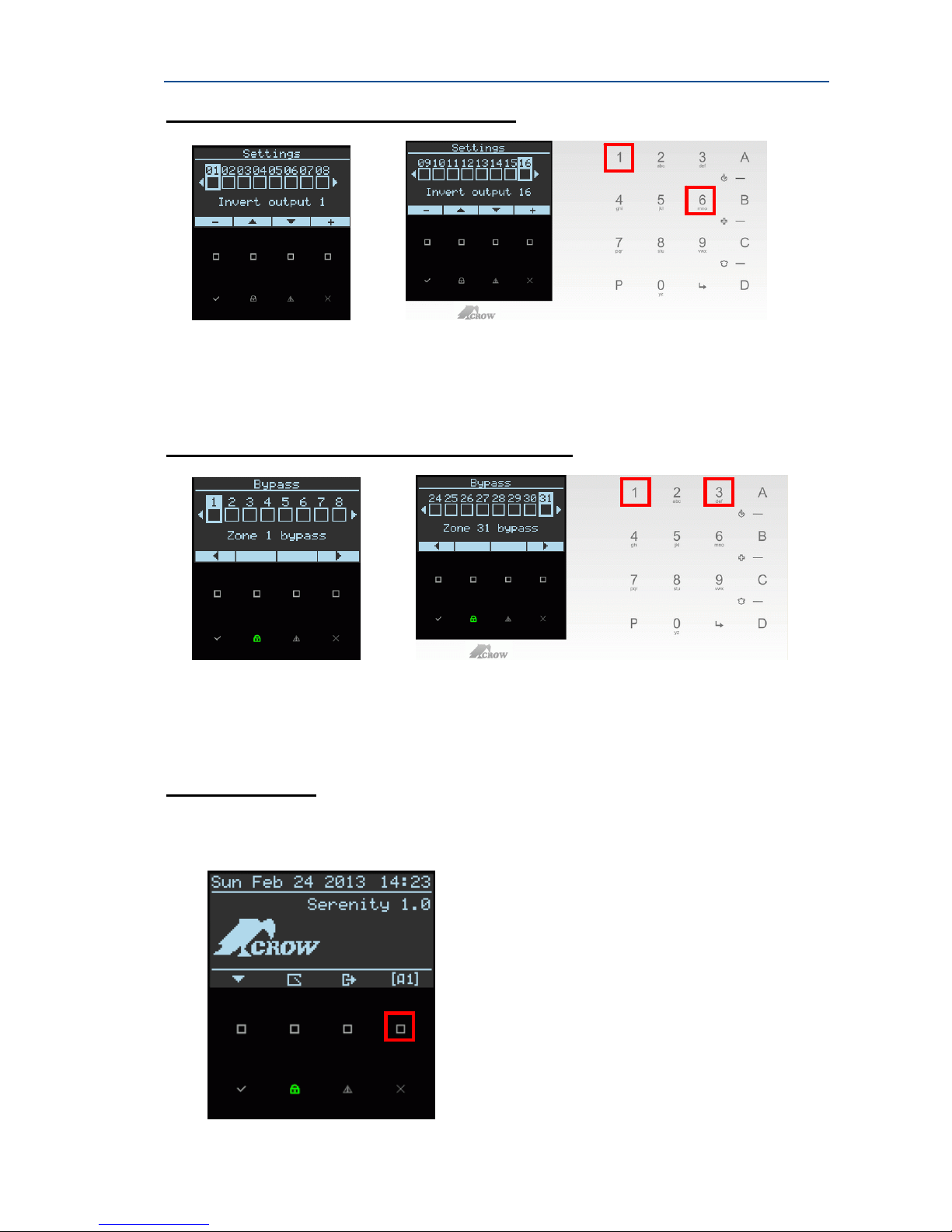
Example 1: Select Zone Number
1.
2.
Option 1: Installer can use the buttons " + or – " to move between zone numbers
Option 2: Installer can use the Keypad keys to move between zone numbers by typing the
zone number "08", installer must type two digits
Page 14
SERENITY – technician Guide
14
Example 2: Select Output Number
1.
2.
Option 1: Installer can use the buttons " + or – " to move between output numbers
Option 2: Installer can use the Keypad keys to move between output numbers by typing the
output number "16", installer must type two digits
Example 3: Select Bypass Zone Number
1.
2.
Option 1: Installer can use the buttons " + or – " to move between output numbers
Option 2: Installer can use the Keypad keys to move between output numbers by typing the
output number "16", installer must type two digits
AREAS Display
The <View Area number> icon will be displayed on the LCD if you first assign at least
one Zone to each of the Areas (P137) and then assign Areas to the keypad (P1097).
To display the Area, use the top right-most button to switch between areas
Page 15

15
Users and Codes
The system provides up to 64 user codes selectable as either 4 to 8 digits. User 1
is a master
user which is assigned 1234 code by default, and has cer tain permissions
to manage the system. User codes are used mainly to arm and disa rm the system or to
access information that is restricted only to authorized users. Each code can be
assigned to one of several authority levels.
Moreover, you can program pendant
users (keyfob transmitters) that will allow you and the other users to easily arm,
disarm and control the system without accessing the panel .
Proximity Tags
The serenity control panel responds to valid proximity tags enrolled to the system. The
proximity tag enables user to perform a certain functions without entering user code,
for instance, arming, disarming, operating an output on/off. Presenting a valid
proximity tag to the control panel which is on disa rmed state, will immediately start the
arm procedure. Presenting the proximity tag once again will DISARM the system.
Installer must note that ARM/DISARM functions are not enabled by default, but if
installer learns tags (explained later on in the guide) via quick programming mode or
by user mode, ARM/DISARM are enabled by default.
The Next symbol presents the RFID location on the Panel
PROGRAMMING TYPES
There are 4 different programming types:
1.
Local Configuration
2.
Quick Programming
3.
Installer Program Mode
4. User Program mode
The first 2 (1, 2) types are accessible from Menu touch button on the main display of the
panel screen (see page 4), the third and fourth types (3, 4) are accessible from keypad key s,
refer to the next pages and learn about all 4 pro gramming types and login options.
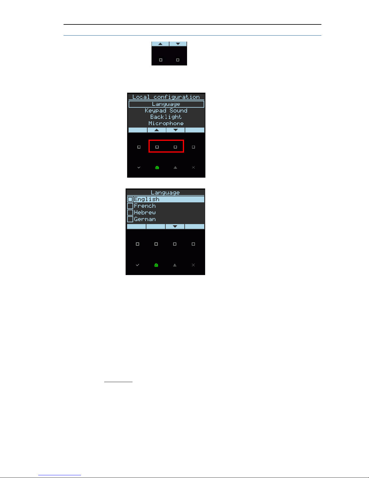
Note: Use the
buttons to move up and down to select the required
programming type, and then use the Enter touch button
1. Local Configuration – contains the following functions:
- Language
- keypad Sound
- Backlight (screen and keypad backlight )
- Microphone (microphone sensitivity )
- Speaker (speaker volume )
Page 16
SERENITY – technician Guide
16
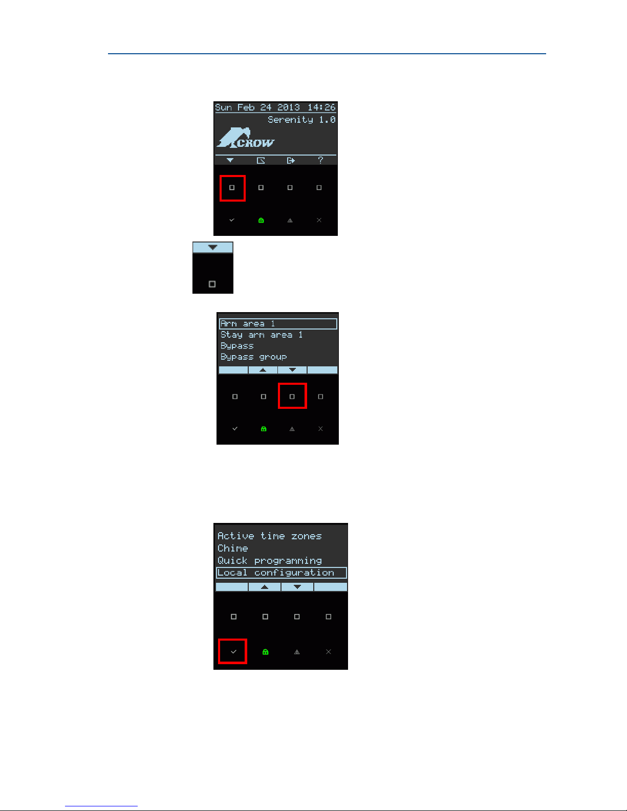
How to enter to the Local Configuration mode
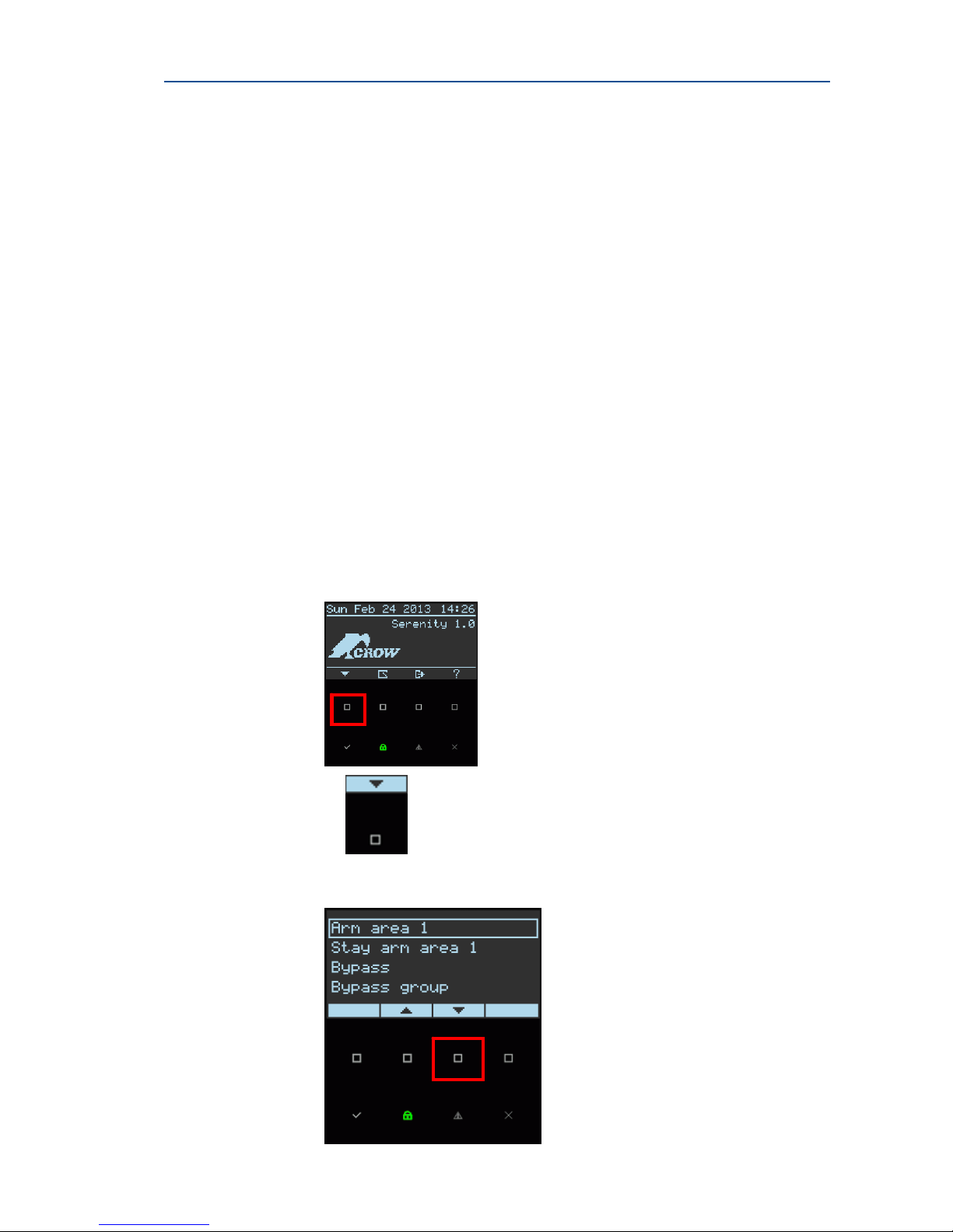
1. Press on the Main Menu button of the main panel screen
2. Use the
button to scroll down until the desired opti on local
Configuration mode is displayed
Note: The Arm area 1 is displayed by default, each of the other areas' options should
be displayed respectively when you change the <view area number> in the main menu
to the requested area.
3. Press on the Enter button
Page 17
17
4. Use the scroll buttons
to select the required function
5. Press on the Enter button
6. Select the required language and press the Enter button
2. Quick Programming –
This programming mode is used for a rapid and focused programming of the panel.
Further on is a list of the functions available in this programming mode.
For more details on the parameters below, refer to ins tal lation summary table section in
this manual, you can easily find the command description by using the Command number
which appears in command number column in this page.
Note: if this level is used for the first system configuratio n, it is recommended to use the
installer mode after that.
Parameter
1. Installer code.
2. System date and time.
3. Report channels type-> Choose
CID PSTN or CID GSM or SIA PSTN or SMS or
Voice message PSTN, Voice message GSM.
4. Report channels phone number
Or server IP addresses 1-4.
5. Backup channels 1-4.
6. Area 1 acc numbers CH 1-4.
7. Area 2 acc numbers CH 1-4.
Page 18
SERENITY – technician Guide
18
8. Area 3 acc numbers CH 1-4.
9. Area 4 acc numbers CH 1-4.
10. Area names 1-4.
11. Area exit delay time 1-4.
12. Learn radio zone 1-32.
13. Exit Delay zone 1-32.
14. Stay mode zone 1-32.
15. Zone names 1-32.
16. Zone 1-32 assigned to area 1.
17. Zone 1-32 assigned to area 2.
18. Zone 1-32 assigned to area 3.
19. Zone 1-32 assigned to area 4.
20. Zone entry delay time 1-32.
21. User names 1-4.
22. User codes 1-4.
23. Learn Pendant user 1-4.
24. Learn user 1-4 Access tag.
25. User 1-4 assigned to area 1.
26. User 1-4 assigned to area 2.
27. User 1-4 assigned to area 3.
28. User 1-4 assigned to area 4.
29. Remote access password.
30. Zone walk test.
Note: Installer password is required for this level (please use the keypad to insert the
password). Default password is 000000 (6 zeros).
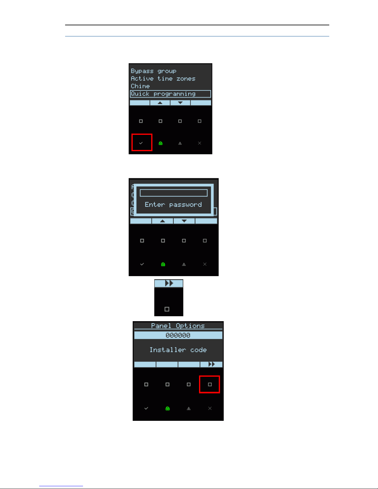
How to enter to the Quick Programming mode
1. Press on the Menu button of the main panel screen
2. Use the button
to move down until the desired option Quick
programming mode is displayed
Page 19
19
3. Press on the Enter button
4. Insert the installer password and press on the 'E nter ' button
5. Use the touch button
to move through all Quick programming menu
Page 20
SERENITY – technician Guide
20
3. Installer Program Mode – This programming mode is the full programming
version mode and it is accessible from keypad
keys.
Note: You can find the full programming address in this guide on "installation
summary tables" chapter, page no. 26
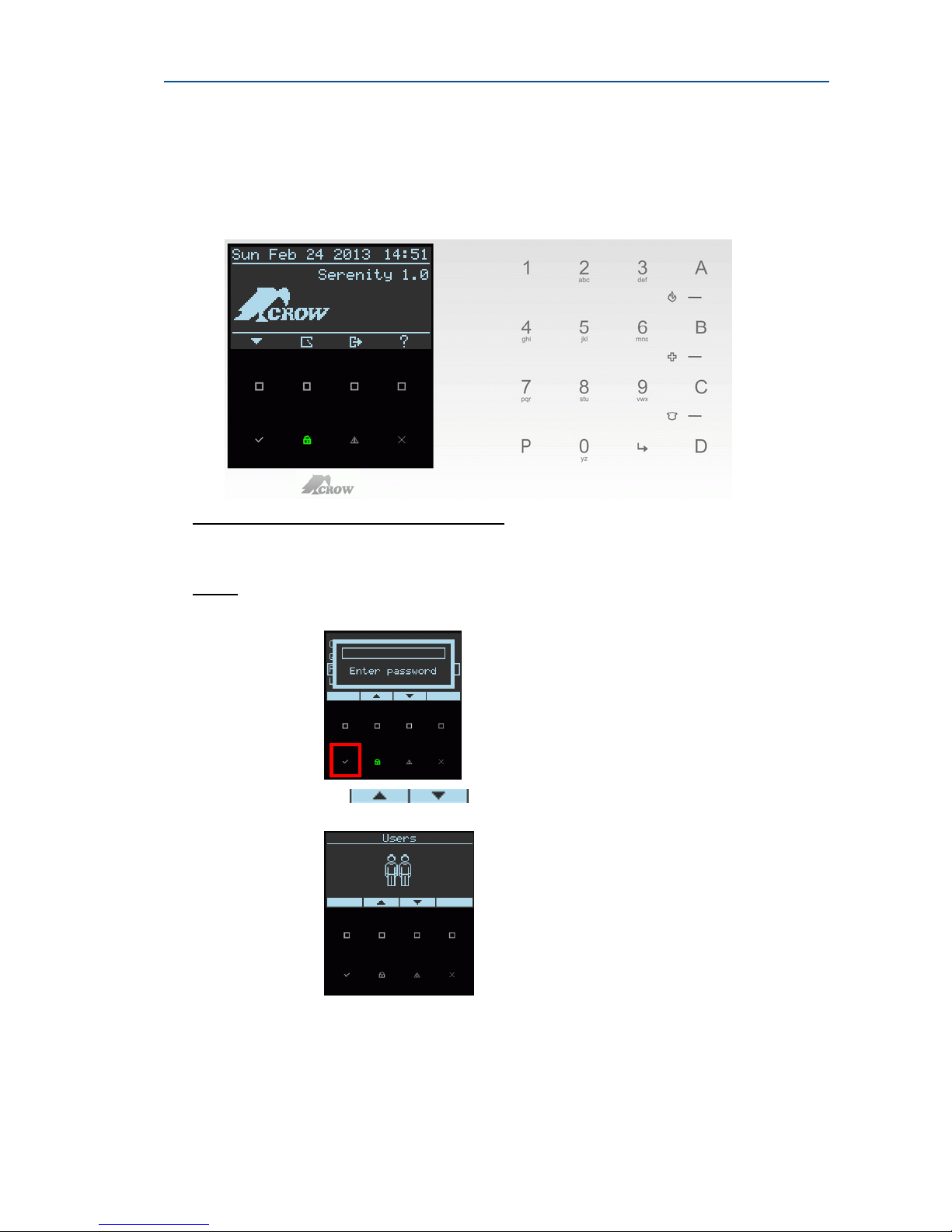
How to Enter to the Programming Mode
To enter Installer Programming mode
To Enter installer programming mode by using the keypad :
Press P<000000>Enter (notice : P=Program E=Enter )
Note:
Default installer password is 6 zeros (000000)
1. Insert the installer password and press on the enter button
2. Use the buttons
to select the required function and programming
level
4. User Programming Mode – A pre-programmed level which is for
programming level of end user (User mode), and it is restrict ed to certain
programming actions which will be described on the next page. Access to this level is
allowed from: a) A command from keypad keys or b) from Main menu (if enabled)
. All
programming actions (User program mode) permissions are enabled for USER 1
(code 1234) by default, any other user permissions should be enabled by the
installer.
Page 21
21
User 1 is a super user according to P22 (User can change all code).
for regular user not all screens are available.
User programming access options
1. Insert a syntax command From Keypad keys: P<user code>E (e.g. P1234E)
If the 'Programming' level was enabled from Keypads level by the installer:
2. From Main Menu ProgrammingEnterInsert User Code (1234)
End User Permissions Programming
DefaultpermissionsforUser1
1. Users->User setting->select User # code 1-64. (User 1 code: 1234)
->User name 1-64.
->Time zone assignment-> User 1 controlled by time zone 1-8
-> Permissions->User 1 can allow access to Installer.
-> Pendants ->Learn pendent 1-64
->Find pendent
->delete user pendent 1-64.
-> Access tag ->Learn user tag 1-64
->Find access tag
->delete user tag 1-64.
2. Outputs->radio output->Learn radio output 1-16.
->Find radio output.
->delete radio output 1-16.
Page 22

SERENITY – technician Guide
22
3. Clock and timers->System date and time->
->System date and time
-> Daylight saving
->GMT zone
->Date format->
->European DD.MM.YYYY
->American MM.DD.YYYY
4. Time zones->Settings->Time zone start 1-8
->Time zone end 1-8.
->Time zone 1-8 day.
->Time zone password 1-8.
->Holidays 1-8.
->Area assignment->Time zone 1-8 assigned to area 1-4.
->Output assignment->Time zone 1-8 assigned to output 1-16.
->User assignment->User 1-64 controlled by time zone 1-8.
5. Zones->Radio zones->Learn radio zone 1-32.
->Find radio zone.
->Delete radio zone 1-32.
6. Report channels->Settings->
channel 1-8 phone number
7. Communication->Remote access ->
-> Remote access password.
-> Remote access only if disarmed.
-> Enable direct remote access.
8. Misc ->Panel options ->direct access to config for installer.
->Voice guide ON/OFF
-> Control panel title.
-> User options->Hide user codes from installer.
-> Voice mail at disarm.
->diagnostic->battery voltage.
->Zone walk test.
->RSSI test.
->GSM module info.
->Ethernet module info.
->Manual test connect 1-8 ch.
Page 23

23
Serenity Quick Programming Guide
The default settings of this panel have been chosen to allow the system to be up and
running with a minimum of programming. As a result, there are normally only a handful
of program definitions that need to be changed to get the system fully functional.
Thinking of the immediate needs of the customer, we created the "Quick
Programming" as a way to quickly set up the Serenity system.
Note: Quick programming menu covers selected parts of the pro g ramming options in
the Serenity. To access all options, you will mostly need Installer mode (for more
details, see the "Installation Summary Tables" section of the guide)
Note: you can always return the system to factory default from installer programming level
(see address P340E)
Programming the Unit
Important Notice: Installer can choose whether he/she wishes to use the quick
programming through the main menu as described previously in th is manual (see How
to enter to quick programming mode on page 14) or to use the address command
directly as will be shown in the "Installation Summ ary Tables" section. Installer may use
the following recommended steps sequence or can select spe cifi c requested steps
according the installation type.
!!!!!! Note:
By default there are no detectors assigned or learned in the control panel, so
any attempt of arming the system will be denied until a detector i s learned
Quick Programming mode: Main menu Quick Programming 000000 Enter
Step 1: Program the Installer Code
Address Description Default
P310E
Installer Code
- This code is used to enter full Installer
Programming mode. The default installer code is 000000. The
Installer Code must be between 4-8 digits in length if parameter is
enabled in (P327)
The default
installer code
is 000000
Step 2: Set the System Date & Time
Address Description Default
P120E
System Date
- The Real Time Clock controls the Time-zones,
the timing of automatic test connections and is used to Time
and Date stamp the events in the Event Buffer.
Ensure this is set
correctly at the time of installation so that the functions affected by it
will work properly. The clock is programmed in 24 hour format (e.g.
00:00-23:59)
Disable
Step 3: Report Channels Type
Installer should choose and enable the report channel type
Address Description Default
P195E
CID PSTN - Set channel type as ContactID PSTN. Need to set
PSTN enabled to use this type of channel. Default assignment:
channels 1,2 - ContactID PSTN, channels 3,4,5 - voice message
(see
Description)
Page 24

SERENITY – technician Guide
24
Address Description Default
PSTN, channel 6 - TCP/IP, channel 7 - voice message GSM and
channel 8 - ContactID GSM.
P196E
CID GSM - Set channel type as ContactID GSM. Need to set
GSM CID enabled to use this type of channel. Default
assignment: channels 1,2 - ContactID PSTN, channels 3,4,5 voice message PSTN, channel 6 - TCP/IP, channel 7 - voice
message GSM and channel 8 - ContactID GSM.
CID GSM
works if GPRS
is disable
P197E
SIA PSTN - Set channel type as SIA PSTN. Need to set PSTN
enabled to use this type of channel. Default assignment:
channels 1,2 - ContactID PSTN, channels 3,4,5 - voice message
PSTN, channel 6 - TCP/IP, channel 7 - voice message GSM and
channel 8 - ContactID GSM.
(see
Description)
P198E
SMS - Set channel type as SMS. Need to set GSM IP enabled or
GSM CID enabled to use this type of channel. Default
assignment: channels 1,2 - ContactID PSTN, channels 3,4,5 voice message PSTN, channel 6 - TCP/IP, channel 7 - voice
message GSM and channel 8 - ContactID GSM.
SMS works if
CID GSM is
enable
P199E
Voice Message PSTN - Set channel type as Voice Message
PSTN. Need to set PSTN enabled to use this type of channel.
Default assignment: channels 1,2 - ContactID PSTN, channels
3,4,5 - voice message PSTN, channel 6 - TCP/IP, channel 7 voice message GSM and channel 8 - ContactID GSM.
(see
Description)
P200E
Voice Message GSM - Set channel type as Voice Message GSM.
Need to set GSM IP enabled or GSM CID enabled to use this type
of channel. Default assignment: channels 1,2 - ContactID PSTN,
channels 3,4,5 - voice message PSTN, channel 6 - TCP/IP,
channel 7 - voice message GSM and channel 8 - ContactID GSM.
(see
Description)
Step 4: Report Channels Phone
Address Description Default
P202E
Phone Number or Server Address – Can be up to 8 phone
numbers (for channels defines as PSTN/GSM/Voice/SMS) or 8
server addresses (for channel defined as TCP-IP/GPRS). The
length is up to 50 characters long (digits only for phone numbers
and characters/digits for server address).
Note: once phone number is inserted, the channel is set as an
active channel automatically.
Disable
Step 5: Backup Channel
Address Description Default
P203E
Channel Backup - This channel will be selected if main channel
has failed to open connection or deliver a message.
Note:
1. A channel can directly have only one backup channel. You
can indirectly set more than one backup channel by
creating a chain of backup channels (For example, Active
channel 1 has channel 2 set as backup, channel 2 has
channel 3 as backup and so on)
2. You can set a channel as backup to two or more active
Ch 2 BA ch.1
Ch 4 BA ch.3
Page 25

25
Address Description Default
channels, but if the active channels fail simultaneously,
the backup will send a report only from the first channel
to fail
Step 6: Areas Account Number
Address Description Default
P206E
Account Number
- - When reporting to a monitoring
Station there must be a unique account code programmed to
identify the area\s reported.
Each area has an account code. The account code is up to 4
characters for all protocols, except SIA and Voice message\SMS
(see notes below).
Each character can be a number from 0-9 as well as the special
characters B, C, D, E & F.
Take note that the number must be different than zero (0000 or
000000).
NOTE:
1. SIA protocol- 6 characters
2. All other protocols – 4 characters
3. You can use the characters 0-9 B,C,D,E,F
4. You don't need an ACC number When channel is
programmed as Voice message/SMS protocol
All Zeros
A letter - not
in use
Step 7: Area Names
Address Description Default
P93E
Area Name
- Enter the Area name, up to 16 characters
" Area #"
Step 8: Area Exit Delay Time
Address Description Default
P74E
Exit Delay Time
(sec) - Each Area can have its own exit delay
time. The delay can be programmed from 1-255 seconds in one
second increments. If the exit delay is set to '0' the panel w ill
be instantly armed.
60
Step 9: Learn Radio Zone
Address Description Default
P177E
Learn Radio Zone
- Radio detector must be enrolled into the
panel before it can be used. pressing of Detector's tamper
switch will be used for learning operation
Disable
Step 10: Exit Delay Zone
Address Description Default
Page 26

SERENITY – technician Guide
26
Address Description Default
P132E
Exit delay zone- Zone should be closed for ready to arm. It
will not cause an instant alarm if triggered during the exit delay
time.
Enable
Step 11: Stay Mode Zone
Address Description Default
P130E
Stay mode zone-Zone will cause alarm if triggered when Stay
Mode is armed. This feature is normally used for arming just
part of the alarm at night time.
Enable
Step 12: Zone Names
Address Description Default
P183E
Zone Name
- Set the zone name, up to 16 characters
" Zone #"
Step 13: Zone Assign to Area
Address Description Default
P137E
Zone assigned to area- This option assigns the Zone to Area.
If a Zone is assigned only to one area it will activate if specified
area is armed. If zone assigned to more than one area it will
activate only when all assigned areas are armed. By default all
zones assigned to Area 1.
(see
Description)
Step 14: Zone Entry Delay Time
Address Description Default
P174E
Armed zone entry delay time (sec
) - Each Zone has its own
Entry Delay time when in the Full Armed State. The delay can
be programmed from 0-9999 seconds in one second
increments. If the entry delay is set to 0 the zone will be an
instant zone
20 sec for zones
1 & 2
Step 15: User Names
Address Description Default
P2E
User Name - Set the user name.
Enter name up to 16 characters
"user #"
Step 16: User Codes
Address Description Default
P1E
User Code - Enter user code (4-8 digits)
1234 (USER 1 )
Step 17: Learn Pendant
Address Description Default
Page 27

27
Address Description Default
P27E
Learn pendant - Save new pendant in memory, pressing of
Pendant's panic Button will be used for learning operation
Disable
Step 18: Learn Access Tag
Address Description Default
P33E
Learn access tag
- An Access Tag/Card must be enrolled into
the panel before it can be used. The rights for tag or card for
each user is defined by options [P36] / [P37] (Arm/Disarm) or
[P386] / [P387] (Turns output on/off).
Disable
Step 19: User Assigned to Area
Address Description Default
P14E
User Assigned To Area- If a User has this option on, they can
Arm/Disarm all zones assigned to Area
All users
assigned to
area 1
Step 20: Remote Access Password
Address Description Default
P236E
Remote Access Password
– the password at this address is
the password code that will be used to allow access to the
control panel when using remote PC application. Up to 8 digits
Disable
Step 21: Walk Test
Address Description Default
P343E
Walk Test - This address is used to start walk-test mode while in
installer or user program mode. By walking past all of the
detectors connected to the system and activating them, the
associated zone will latch up at the keypad to allow verification
that all zones are working properly. By pressing Enter or Cancel
button, walk-test mode will be terminated. The results of the walktest will be shown on the screen to verify which detectors were
triggered during walk-test mode.
Disable
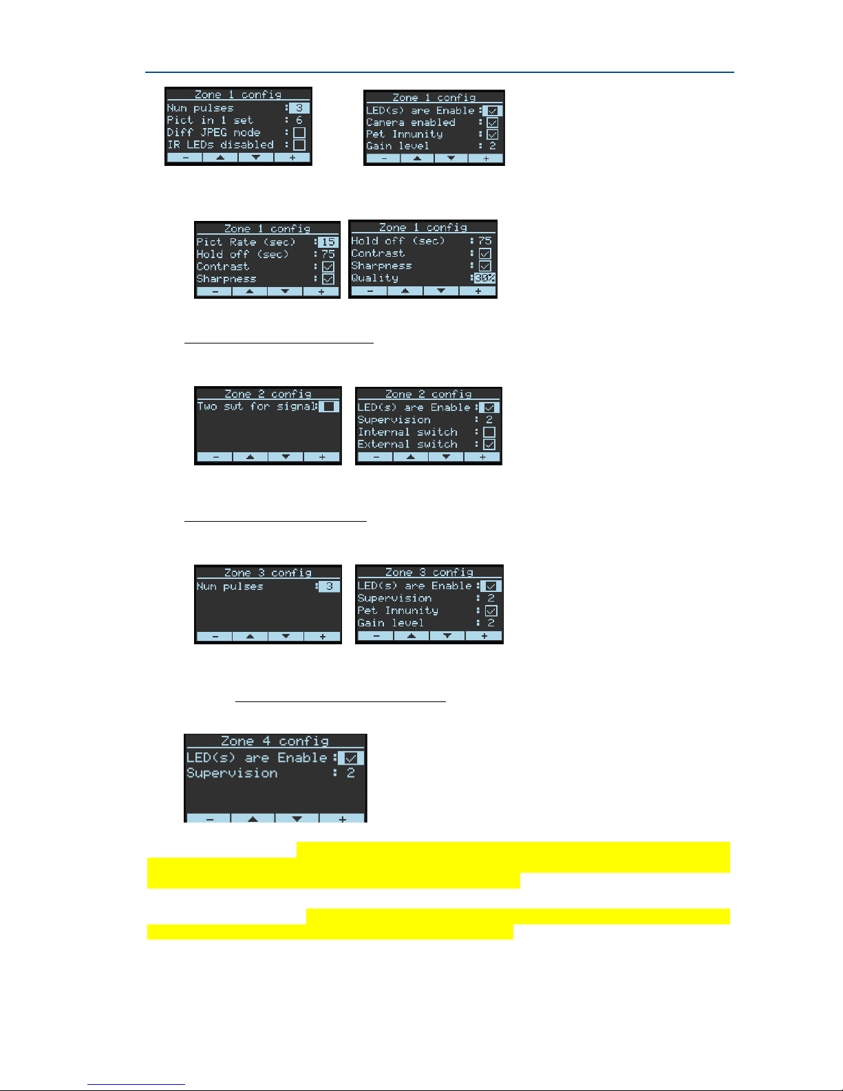
Setting of Zone Configuration
Programming of Zone Configuration, such as Gain Level, Pet Immunity, LEDs Enable,
Supervision, and more of the serenity series, will be defined manually by the installer
only from programming level.
By Default, all Zone Config screens are not visible, "Zone Config screens" (P181) will be
visible right after a detector was learned and enrolled into system through "learn radio
zone" (P177) procedure.
Zone Configuration Screen Examples:
1. PIR Camera Zone Config screens
Page 28
SERENITY – technician Guide
28
FW2 MAG Zone Config screens
2.
FW2 PIR Zone Config screens
3.
4. FW2 SMOKE Zone Config screens
Important Notice: 1.Setting or changing of Zone Configuration will be implemented
into the detector configuration in the next event such as Open
Zone \Open Tamper \ supervision.
2. For return to default definition after learning, user can enter
P180-"Radio zone reset config".
Page 29

29
Page 30

SERENITY – technician Guide
30
Installation Summary Tables
USERS Page No.
User Settings……………………………………………………………………….. 32
User Options………………………………………………………… ……… ………32
User Type …………………………………………………………......................32
Area Assignment……………………………………………………………….…...33
Output Assignment …………………………………………………………………33
Keypad Assignment…………………………………………………………………33
Time Zone Assignement……………………………………………………..….33
Permissions………………………………………………………....................34
Pendants………………………………………………………………………………….34
Access Tag……………………………………………………………………………….35
OUTPUTS
Settings……………………………………………………………………………………36
Output Type …………………………………………………………..................37
User Assignment…………………………………………………………………....37
Time Zone Assignment ……………………………………………………….…37
Keypad Assignment…………………………………………………………….….38
Signals to Output…………………………………………………………………...38
Timing………………………………………………………...........................39
Radio Output…………………………………………………………………………..39
Output Name…………………………………………………………………………..40
AREAS
Settings…………………………………………………………………………………...40
Timers and Delays………………………………………………………………..…41
Zone Assignment…………………………………………………………………….41
User Assignment ………………………………………………………………...…41
Keypad Assignment…………………………………………………………….….41
Time Zone Assignment……………………………………………………….….42
Report Channel Assignment…………………………………………….….…42
Signals to Outputs…………………………………………………………….……42
Beeps to Keypad…………………………………………………………….………44
Area Names…………………………………………………………………. .….……44
Page 31

31
KEYPADS
User Settings……………………………………………………………………………44
Area Assignment……………………………………………………………………..44
User Assignment …………………………………………………………………….45
Output Assignment …………………………………………………………………45
Alarms to Output……………………………………………………………………..45
Beeps to Keypad………………………………………………………………………46
Radio Keypads…………………………………………..………….…………………47
Control Menu…………………………………………………………………….......47
Function Buttons……………………………………….…………………………….47
KEYSWITCH
Settings…………………………………………………………………………………….47
Options………………………………………………………………………………….. 47
CLOCK & TIMERS
System Date and Timers………………………………………………………….48
Date Format……………………………………………………………………………..48
Timers ………………………………………………………….............................48
Delays……………………………………………………………………………………...49
ZONES
Status………………………………………………………………………………….……49
Area Assignment……………………………………………………………………..50
Working Mode …………………………………………………………………..……50
Options………………………………………………………………………………….…51
Zone Response Time………………………………………………………….…..51
Alarms to Output……………………………………………………….............52
Beeps to Keypad……………………………………………………………………..53
Delays and Timers…………………………………………………………………..54
Radio Zones……………………………………………………………………………..54
Re-Trigger………………………………………………………......................54
Zone Names…………………………………………………………………………….55
TIME ZONES
Settings…………………………………………………………………………………….55
Area Assignment……………………………………………………………….……..56
Output Assignment ……………………………………………………………….…56
User Assignment ……………………………………………………………………..56
Page 32

SERENITY – technician Guide
32
REPORT CHANNELS
Channel Type…………………………………………………………….…………….56
Settings…………………………………………………………………………………...57
Area Account Number Assignment …………………………………..……58
Reporting Options……………………………………………………………….……58
COMMUNICATIONS
Remote Access………………………………………………………………….…...60
Phone Line Options………………………………………………………….……..61
PSTN ……………………………………………………………………….…………..…61
GSM…………………………………………………………………………..…………….62
TCP-IP……………………………………………………………………….............62
CUN-BUS……………………………………………………….......................62
Contact ID Codes………………………………………………………………...…63
SIA Codes…………………………………………………………………………..……63
Voice Message Numbers…………………………………………………………63
Control Code Number……………………………………………………………..64
MISCELLANEOUS
Chime Control………………………………………………………………………….65
Panel Options…………………………………………………………………………..65
User Options ………………………………………………………………………..…67
Voice Mail At Disarm…………………………………………………………….…68
Diagnostic……………………………………………………………………………....68
Extender Type…………………………………………………………………………69
Extender Options………………………………………………………………….…69
Page 33

33
1: Users
1.1: Users/Users Settings
Address Description Default
P1E
User Code - Set the user code (password). Enter user code (4-8
digits)
Code 1 defaults
to 1234.
This means that
User 1
automatically
gets the code
1234
P2E
User Name - Set the user name.
Enter name up to 16 characters
"user #"
1.2: Users/User Options
Address Description Default
P3E
User Code can arm all areas assigned at address [P14]
Enable
P4E
User Code can arm Stay Mode for all areas assigned at
address [P14]
Disable
P5E
User Code can disarm all areas assigned at address [P14]
Enable
P6E
User Code can disarm Stay Mode for all areas assigned at
address [P14]
Enable
P7E
Security Guard User - User Code can arm all areas assigned
at address [P14], but may only disarm if the panel is currently
armed and in the alarm state
Disable
P8E
Latchkey Mode User - User will arm the alarm in Latchkey
Mode. If a user with this option on disarms the alarm no disarm
report will be sent via the dialler. If Latchkey Mode is armed
and a user with this option off disarms the alarm a disarm
report will be sent to alert parents when their children have
returned home. Reporting of Latchkey Disarm is enabled at
[P229]. If a Voice report is desired the message is assigned at
[P284].
Disable
P9E
Code required after access tag - After presenting access tag
user has to enter a valid user code
Disable
1.3: Users/User Type
Address Description Default
P10E
Keypad User - Codes can be used to Arm/Disarm all or part of
the alarm or they can be used to operate outputs for access
control purposes. Users can be assigned to keypads and so can
outputs so that a User assigned to multiple outputs (which can
in turn be linked to doors) can operate only the door assigned
to the keypad they are using
Enable
P11E
Pendant User - Radio keys can be used to Arm/Disarm all or
part of the alarm or they can operate outputs directly. Unlike
user codes, a radio key cannot be assigned to a keypad so if a
radio key is assigned to more than one output and the radio
key is operated, all of the outputs assigned to the radio key will
Disable
Page 34

SERENITY – technician Guide
34
Address Description Default
turn on
P12E
Access Tag User - Access Tag can be used to Arm/Disarm all
or part of the alarm or it can be used to operate outputs for
access control purposes.
Disable
P13E
Remote Control User - This option defined user rights for
remote control of the control panel via phone line by DTMF
control code numbers, via SMS or via WEB-server and
smartphone application.
User 1 only
1.4: Users/Areas Assignment
Address Description Default
P14E
User Assigned To Area- If a User has this option on, they can
Arm/Disarm all zones assigned to Area
all users
assigned to
area 1
1.5: Users/Output Assignment
Address Description Default
P15E
User code turns output on -Any user can be allowed to turn
an Output ON. This Function can be used to control external
devices via the panel keypad with a User assigned to that
Output. Once an Output is turned ON by a User, the Output can
turn OFF again automatically if a reset time is assigned to the
Output, or it can be turned off by the same user or by a
different user with the next program location
Disable
P16E
User code turns output off -Any user can be allowed to turn
an Output OFF. This Function can be used to control external
devices via the panel keypad with a User assigned to that
Output. Once an Output is turned OFF by a User, the Output
can be turned on by the same user or by a different user with
the previous program location
Disable
1.6: Users/Keypad Assignment
Address Description Default
P18E
User can operate at keypad -Any user can be assigned to
only operate certain Keypads. This option controls whether a
code or access tag User can Arm/Disarm from certain keypads.
This option does not restrict users from operating outputs from
a particular keypad (this is done at location [P98])
Enable
1.7: Users/Time Zone Assignment
Address Description Default
P19E
User Controlled by Time Zone - When the user is controlled
by time zone, its keypad code, access tag and pendant
deactivated all the time, when the time zone is not started or
finished. Only when the time zone is started, the user can
perform actions in the system in accordance with its rights as
Disable
Page 35

35
Address Description Default
defined by configuration.
1.8: Users/Permissions
Address Description Default
P20E
User can view memory and status - If this option is off, user
cannot enter memory view mode, statuses and active time
zones.
Enable
P21E
User can change his code - If a User has this option on ,he is
considered as a super user that means the menu of user mode is open
User 1 only
P22E
User can change all codes - If a User has this option on, user
can access User Programming Mode and change All User code
numbers.
User 1 only
P23E
User can allow access to installer mode
- If a User has this
option on, access to Installer Program Mode is only possible by
entering the installer code, and after that, the code of this User.
To use it, option "Direct access for installer to programming
mode" [P313] should be switched to off in User Mode.
User 1 only
Available on
User Mode only
P24E
User can change phone or address
- If a User has this
option on, user can access User Programming Mode and change
the telephone and call divert numbers.
Enable
User 1 only
P25E
User can change the clock - If a User has this option on, user
can access User Programming Mode and change the Time &
date settings and set daylight saving time.
Enable
User 1 only
P26E
User can learn radio devices
- If a User has this option on,
user can access User Programming Mode and Learn a new
Radio Key or Wireless Zone Device. The user can also remove
radio devices or find what location number a device is stored at.
User 1 only
1.9 Users/Pendants
Address Description Default
P27E
Learn pendant - Save new pendant in memory
, pressing on
Pendant's panic Button will be used for learning operation
Disable
P28E
Find pendant
- Find existing pendant in memory
Disable
P29E
Delete pendant - Delete existing pendant from memory
Disable
P30E
Pendant can disarm during alarm only
- If this option is on,
pendant can disarm the alarm during alarm only. If this option
is off, the pendant cannot disarm the panel in any state.
Disable
P31E
Pendant can disarm during entry delay only
- If this option
is on, pendant can disarm the alarm during alarm only. If this
option is off, the pendant can disarm the panel in any state.
Disable
P392E
Pendant Panic Alarm to Output - A Pendant Panic Alarm can
be assigned to an Output or multiple Outputs. This can be used
to operate an audible or visual alarm connected to the Output
Outputs
1,2,11-16
Page 36

SERENITY – technician Guide
36
Address Description Default
P32E
Pendant Buttons - Assign function to pendant's button. By
default button1 is assigned to Disarm, button2 - Arm, button 3
- Stay arm, button 4 - Switch output 1, button 5 - Panic.
(see
Description)
1.10: Users/Access Tag
Address Description Default
P33E
Learn access tag
- An Access Tag/Card must be enrolled into
the panel before it can be used. The rights for tag or card for
each user is defined by options [P36] / [P37] (Arm/Disarm) or
[P386] / [P387] (Turns output on/off).
Disable
Note: if access
tag is learned
by User mode
the options of
'Arm' and
'Disarm' are
automatically
enabled
P34E
Find access tag
-If you have an Access Tag or Card loaded
into the panel but are unsure which location (User #), pressing
[P34] while in Program Mode will start 'Find' Mode. Present the
Access Tag or Card you wish to find to a proximity reader
connected to the panel. If the Tag or Card is in memory the
keypad will display the number where the Tag or Card is stored.
Disable
P35E
Delete access tag -If you wish to delete a single Access Tag or
Card, entering [P35] and user number while in Program Mode
will delete the stored code against that user.
Disable
P36E
Access tag can arm
- If this option is on, access tag can arm
all areas assigned at [P14]
Disable
P37E
Access tag can disarm
- If this option is on, access tag can
disarm all areas assigned at [P14]
Disable
P386E
Access tag turns on output - Any user's access tag can be
allowed to turn an Output ON. In this case Arm/Disarm
functionality for selected tag is not relevant. This Fun ction can
be used to control external devices via access tags. Once an
Output is turned ON by a User, the Output can turn OFF again
automatically if a reset time is assigned to the Output, or it can
be turned off by the same user or by a different user with the
next program location
Disable
P387E
Access tag turns off output - Any user's access tag can be
allowed to turn an Output OFF. In this case Arm/Disarm
functionality for selected tag is not relevant. This Fun ction can
be used to control external devices via access tags. Once an
Output is turned OFF by a User, the Output can be turned on by
the same user or by a different user with the previous program
location
Disable
Page 37

37
2: Outputs
2.0: Outputs/Settings
Address Description Default
P39E
Invert Output
-This option is used to invert the normal state
of the output. The panel uses open collector transistor switches
and the default state of all outputs is off (open). When in alarm
the transistor is turned on and the output goes low (0V). The
invert option reverses this function.
Disable
P40E
Temporary output Disable - This option allows a technician
to select any output/s to be temporarily disabled for one alarm
or armed cycle, e.g. by selecting Outputs 1-16 at this location
then leaving program mode, outputs 1-16 will not turn on
following any alarms. The technician is now free to arm the
system to test all monitoring signals without having any
internal and/or external alarms activating. When the alarm is
reset or disarmed all outputs will return to normal.
Disable
P41E
Lockout Output -This option is used to limit the output to one
operation per arming period.
Disable
P42E
Pulse Output on Kiss-off Following Arming
- This option
will cause the Output to short single pulse when any area is
armed and the message has been kissed off by monitoring
company.
Disable
P382E
Output Disable During Disarm- This option will cause the
Output to be disabled when all areas in DISARM state. It is
designed to keep audible alarms silent when the full system
disarm, but part of alarms (like Panic or Fire alarm) still turns
audible alarms to on regardless of this setting.
Enable
P43E
Disable During Alarm Report Delay
-This option will cause
the Output to be disabled when the reporting delay is active. It
is designed to keep external audible alarms silent when the
reporting delay is active (allowing internal alarms to warn that
the alarm will be reported to monitoring if not unset) but if the
alarm hasn’t been reset before the timer expires the external
alarm will sound.
Disable
P44E
Mute for 10 sec on key-press if alarm
- As you enter your
code at the keypad, it can be quite difficult to turn the alarm off
due to being unable to hear the beeps over the siren's blare. If
this option is turned on the selected output/s will be silenced
(turn off) for 10 seconds on the first button press at any
keypad. This should allow easy Disarming of the alarm by a
valid User. If the alarm is not turned off within the 10 seconds,
the outputs will turn on again. This function will only work once
during an Armed cycle and the panel must be Disarmed before
it will work again.
Disable
P45E
Enable Output Monitoring- If this option is enabled, the
control panel monitors the status of the outputs by voltage
level for wired outputs or coming supervision messages for
wireless outputs. If disabled - monitoring the state of the
outputs will disabled.
Disable
Page 38

SERENITY – technician Guide
38
2.1: Outputs/Output Type
Address Description Default
P46E
Steady Output
- The output will change its state when an
alarm occurs
Enable
P47E
Single Pulse Output
- This option produces a single pulse at
the output when an alarm occurs (the pulse time is the value
programmed at address [P61]).
Disable
P48E
Flash Output - When the output is turned on this option
causes the output to flash at a rate set at address [P61]. One
use is to flash a lamp during an alarm.
Disable
2.2: Outputs/User Assignment
Address Description Default
P1015E
User code turns this output on
- Any user can be allowed to
turn an Output ON. This Function can be used to control
external devices via the panel keypad with a User assigned to
that Output. Once an Output is turned ON by a User, the
Output can turn OFF again automatically if a reset time is
assigned to the Output, or it can be turned off by the same user
or by a different user with the next program location.
Disable
P1016E
User code turns this output off
- Any user can be allowed to
turn an Output OFF. This Function can be used to control
external devices via the panel keypad with a User assigned to
that Output. Once an Output is turned OFF by a User, the
Output can be turned on by the same user or by a different
user with the previous program location
Disable
2.3: Outputs/Time Zone Assignment
Address Description Default
P1192E
Time Zone Assignment
- If a time-zone is assigned to an
output it will turn the output on when the time-zone starts and
turn the output off when it finishes.
Disable
2.4: Outputs/Keypad Assignment
Address Description Default
P1098E
Keypad is linked to Output
- A Keypad can be assigned to an
Output or multiple Outputs. If a Keypad is not assigned to an
Output a User cannot turn that Output On or Off from the
Keypad. This feature is useful when using the access control
features of the panel, eg a User may be allowed to operate
more than one Output with their code but they will be limited to
just the Output assigned to the Keypad they are using
Disable
2.5: Outputs/Signals to Output
Address Description Default
Page 39

39
Address Description Default
P49E
Mains Fail to Output
- This option is used to assign a Mains
Fail alarm to an Output
Disable
P50E
Fuse Fail to Output
-This option is used to assign a Fuse
Failure alarm to an Output. The on-board fuses are thermally
activated. If excessive current is drawn from a fuse it will
disconnect the power until the problem is resolved. There are
two thermal fuses protecting the various 12v DC outputs
Disable
P51E
Battery Low to Output-This option is used to assign a Battery
Low alarm to an Output
Disable
P52E
Monitor output fail to Output
-Assigning monitor output fail
alarm
Disable
P390E
Output tamper alarm to Output - This option is used to
assign an Output tamper alarm to an Output. When output
tamper alarm occurs, any output can be turned to on.
Disable
P54E
Communication fail to Output
-This option is used to assign a
Communication Failure alarm to an Output
Disable
P55E
Radio Zone Supervised Fail to Output
-This option is used to
assign a Radio Detector Supervisory Fail alarm to an Output
Disable
P56E
System Tamper to Output
- This option is used to indication
the panel tamper alarm by specified Output. The Output turns
to on in arm or stay arm state only.
Enable Outputs
1 & 2 on ARM
state
P57E
Sensor-Watch to Output-This option is used to assign a
Sensor-Watch alarm to an Output. A Sensor-Watch alarm
occurs when a detector has not operated within a set period of
time
Disable
P17E
Duress Alarm to Output -Duress Alarm [P311] can be
assigned to an Output or multiple Outputs. This can be used to
operate an audible or visual alarm connected to the Output. A
Duress alarm is created when the alarm is Disarmed with the
Duress digit preceding a valid User Code
Disable
P58E
Walk Test Pulse to Output
- When the panel is in Walk-test
Mode, this option assigns a one single pulse (one chirp) to the
Output every time a zone is triggered.
Disable
P1059E
Keypad Panic Alarm to Output
- A Keypad Panic Alarm
(pressing C & D buttons together) can be assigned to an Output
or multiple Outputs. This can be used to operate an audible or
visual alarm connected to the Output
Enable Outputs
1,2,11-16
P1099E
Keypad Fire Alarm to Output
- A Keypad generated Fire
Alarm (pressing the A & B) can be assigned to an Output or
multiple Outputs. This can be used to operate an audible or
visual alarm connected to the Output
Enable Outputs
1,2,11-16
P1100E
Keypad Medical Alarm to Output
- A Keypad generated
Medical Alarm (pressing the B & C together) can be assigned to
an Output or multiple Outputs. This can be used to operate an
audible or visual alarm connected to the Output
Enable Outputs
1,2,11-16
P1392E
Pendant Panic Alarm to Output - A Pendant Panic Alarm can
be assigned to an Output or multiple Outputs. This can be used
to operate an audible or visual alarm connected to the Output
Outputs
1,2,11-16
Page 40

SERENITY – technician Guide
40
2.6: Outputs/Timing
Address Description Default
P60E
Output Delay Time
- The 'On' delay allows the operation of the
Output to be delayed by the time programmed at this location.
If set to '0' there will be no on delay and the Output will operate
the instant it is turned on. The time range is 0-36000 seconds.
0s
P61E
Output Pulse Time
- Output Pulse Time affects the time an
output turns on when the pulse timer is used on the Output
(see [P47], [P48]). The pulse time is in 1/10th second
increments so that very quick timing can be achieved. The
maximum value that could be assigned to is 36000 which
corresponds to 1 hour. The parameter valid for wired outputs
only.
20
P62E
Output Reset Time - The Reset time affects the time the
output turns on in case of alarm state. The time range is 036000 seconds
For outputs 1
and 2, 240
sec, all the
rest outputs
endless
P63E
Output Chime Time
- The Chime Mode time affects the time
the output turns on when a Chime Zone is activated. The Chime
time is in 1/10th second increments so that very quick timing
can be achieved.
Min 0 max 36000
20
2.7: Outputs/Radio Output
Address Description Default
P64E
Learn Radio Output
- Save new radio output in memory
Disable
P65E
Find Radio Output
- Find existing radio output in memory
Disable
P66E
Delete Radio Output-Delete existing radio output from
memory
Disable
P184E
Output reset config- This function resets to default
parameters values which were defined in (P185E) of a radio
output.
P185E
Output config - This function set remotely the radio output
parameters such as led on/off, sounder on/off, led and sounder
timeouts, etc.
2.8: Outputs/Output Name
Address Description Default
P67E
Output Name
- Set output name, up to 16 characters
"output #"
3: Areas
3.0: Areas/Settings
Address Description Default
P68E
Code required to bypass zones
- If this option is turned on,
the BYPASS button cannot access Bypass Mode directly. To
Disable
Page 41

41
Address Description Default
enter Bypass mode the User must press BYPASS CODE ENTER
before they can bypass zones
P69E
Code required to Arm
-If this option is turned on, the ARM
button is disabled and the panel requires a code to Arm
Disable
P70E
Arm command required before code to set-This option
determines if the ARM button must be pressed before a code is
entered to Arm an Area
Disable
P71E
Stay command required before code to set stay mode
-
This option determines if the STAY button must be pressed
before a code is entered to Arm Stay Mode
Disable
P72E
Report Arm on Exit Delay
-If this option is on the panel will
report the Arm/Stay signal to a monitoring station when the
exit delay expires. If it is off, the panel will report the arm/stay
signal immediately after the system has been armed
Disable
P73E
Use near and verified alarm reporting for all zones
-To
reduce the possibility of false alarms the panel can require two
alarms on different zones within a 45 minute period before a
full alarm will be sent. If this option is turned on it applies to all
zones assigned to that area. An alarm on a single zone will
send a Near Alarm report to the monitoring station. If no
further alarms occur within 45 minutes the near alarm timer is
reset and a restore is sent for the zone that activated. If the
zone that activated is still in alarm when th e 45 minute timer
expires, a zone bypass for that zone will be sent and the zone
will remain bypassed until the area is disarmed. Any new
alarms after the timer has expired will send another Near Alarm
report. If a second alarm on a different zone occurs within 45
minutes of the Near alarm, an Intrusion Verified alarm report
will be sent. This format applies to all protocols except SIA
PSTN, Voice message PSTN/GSM.
Disable
P393E
Unable to arm if exit zone is open - If this option is turned
on, the system doesn't arm or stay arm the area if one of the
low security zones or exit delay zones is still open after the exit
delay expired.
3.1: Areas/Timers and Delays
Address Description Default
P74E
Exit Delay Time
- Each Area can have its own exit delay time.
The delay can be programmed from 1-255 seconds in one
second increments. If the exit delay is set to '0' the panel w ill
be instantly armed.
60
P75E
Stay Exit Delay Time
- Each Stay Mode Area can have its own
exit delay time. The delay can be programmed from 1-255
seconds in one second increments. If the exit delay is set to '0'
the panel will be instantly armed.
60
Page 42

SERENITY – technician Guide
42
Address Description Default
P76E
Delinquency Delay - Each Area can have its Delinquency time.
The delinquency time monitors the arm/disarms of each Area.
If an Area has not been armed within the set number of days a
delinquency report will be sent. Each time an Area is armed the
delinquency timer is reset. A value of '0' disables the
delinquency monitoring. NOTE: If the default value of '0' is
changed at this location (e.g. a value of 10 is entered meaning
10 days), the next time the area is armed a delinquency restore
message will be sent via the dialer as a test that the function is
operating
Disable
3.2: Areas/Zone Assignment
Address Description Default
P1137E
Zone Assigned to Area
- This option assigns the Zone to
Area. If a Zone is assigned only to one area it will activate if
specified area is armed.
If a zone is assigned to more than one
area, it will activate only when all areas the zone is assigned to are
armed. By default all zones assigned to Area 1.
See comments
3.3: Areas/User Assignment
Address Description Default
P1014E
User Assigned To Area
- If a User has this option on, they
can Arm/Disarm all zones assigned to Area
all users
assigned to
area 1
3.4: Areas/Keypad Assignment
Address Description Default
P1097E
Keypad Assigned To Area
- This option assigns Area to
keypads. If a keypad is assigned to one area only it can Arm or
Disarm only that area and show states only for this area. If
keypad assigned to more than one area, it can be switched to
operate specified area and show states. By default all keypads
assigned to area 1.
All Keypads
assigned to
area 1
3.5: Areas/Time Zone Assignment
Address Description Default
P1191E
Time Zone Assigned to Area
- If P166E, P167E and P168E
are set (see 8.0), and this option is turned on then the Area can
be automatically armed or disarmed by a time-zone/s. You can
assign more than one time-zone to each Area. If assigning
multiple time-zones you should insure that they do not overlap
as this could cause confusion. A Time-zone would typically be
0830-1700 Monday-Friday. An area will turn on when the Timezone ends (e.g. 1700) and turn off when a Time-zone starts
(e.g. 0830)
Disable
Page 43

43
3.6: Areas/Report Channel Assignment
Address Description Default
P1206E
Account Number
- When reporting to a monitoring
Station there must be a unique account code programmed to
identify the area\s reported.
Each area has an account code. The account code is up to 4
characters for all protocols, except SIA and Voice message\SMS
(see notes below).
Each character can be a number from 0-9 as well as the special
characters B, C, D, E & F.
Take note that the number must be different than zero (0000
or 000000).
NOTE:
1. SIA protocol- 6 characters
2. All other protocols – 4 characters
3. You can use the characters 0-9 B,C,D,E,F
4. You don't need an ACC number When channel is
programmed as Voice message/SMS protocol
Disable
3.7: Areas/Signals to Outputs
Address
Description
Default
P77E
Arm Indication to Output
- For monitoring purposes an Arm
indication can be assigned to an Output. This could be used to
start a video recorder or similar device. Each Area can have a
separate arm indication assigned to a different output if
required
Outputs 11-16
only
P78E
Stay Arm Indication to Output
-For monitoring purposes a
Stay Arm indication can be assigned to an Output. Each Area
can have a separate indication assigned to a different output if
required
Outputs 11-16
only
P79E
Disarm Indication to Output
-For monitoring purposes a
Disarm indication can be assigned to an Output. Each Area can
have a separate disarm indication assigned to a different output
if required
Outputs 11-16
only
P80E
Armed Exit Delay Beeps to Output
-When an Area is Armed
it is useful to have the exit delay beeps occurring at the keypad
to warn the User to exit the premises without delay. If the
option is on at this address, that keypad will beep out the exit
delay. The exit beeps occur at one second intervals until the
last 5 seconds at which time they change to 1/2 second
intervals to act as a warning that the delay is about to expire
Disable
P81E
Stay Exit Delay Beeps to Output
-When an Area is Armed in
Stay Mode it is useful to have the exit delay beeps occurring at
the keypad to warn the User to exit the premises without delay.
If the option is on at this address, that keypad will beep out the
exit delay. This option may be turned off for Stay Mode to make
the keypad silent when arming at night time. The exit beeps
occur at one second intervals until the last 5 seconds at which
time they change to 1/2 second intervals to act as a warning
that the delay is about to expire. When arming Stay Mode the
Disable
Page 44

SERENITY – technician Guide
44
exit and entry delays can be cancelled by pressing the ENTER
button following arming of Stay Mode. The next time Stay Mode
is armed, if the ENTER button is not pressed, all programmed
exit and entry delays will apply
P82E
Pendant/Tag Arm Beep to Output-When Arming the alarm
using a Radio Key or Access Tag it is necessary to have some
form of Arm indication. This can be done by pulsing an Output
once when the area is armed (one chirp).
Outputs 11-16
only
P83E
Pendant Stay Arm Beep to Output
-When Arming Stay Mode
using a Radio Key it is necessary to have some form of Arm
indication. This can be done by pulsing an Output once when
the area is armed (one chirp).
Outputs 11-16
only
P84E
Pendant/Tag Disarm Beep to Output
-When Disarming the
alarm using a Radio Key or Access Tag it is necessary to have
some form of Disarm indication. This can be done by pulsing an
Output twice when the area is disarmed (two chirps).
Outputs 11-16
only
P85E
Pendant Stay Disarm Beep to Output
-When Disarming Stay
Mode using a Radio Key it is necessary to have some form of
Disarm indication. This can be done by pulsing an Output twice
when the Stay Mode is disarmed (two chirps).
Outputs 11-16
only
P86E
Arm Pulse to Output
- Double pulse will be applied to selected
output (e.g. siren) indicating arming
Disable
P87E
Stay Arm Pulse to Output
- Double pulse will be applied to
selected output (e.g. siren) indicating arming
Disable
P88E
Disarm Pulse to Output-A single pulse will be applied to
output (e.g. siren) indicating disarming
Disable
P89E
Stay Disarm Pulse to Output
-A single pulse will be applied to
selected output (e.g. siren) indicating disarming selected
Disable
P90E
Pulse output every 5 sec when disarmed
-This option will
cause output to pulse every 5 seconds when the area is
disarmed. The pulse time is linked to the Output Pulse Time.
Disable
3.8: Areas/Beeps to Keypad
Address Description Default
P91E
Armed Exit Delay Beeps to Keypad - When an Area is
Armed it is useful to have the exit delay beeps occurring at the
keypad to warn the User to exit the premises without delay. If
the option is on at this address, that keypad will beep out the
exit delay. The exit beeps occur at one second intervals until
the last 5 seconds at which time they change to 1/2 second
intervals to act as a warning that the delay is about to expire
Enable
P92E
Stay Armed Exit Delay Beeps to Keypad
- When an Area is
Armed in Stay Mode it is useful to have the exit delay beeps
occurring at the keypad to warn the User to exit the premises
without delay. If the option is on at this address, that keypad
will beep out the exit delay. This option may be turned off for
Stay Mode to make the keypad silent when arming at night
time. The exit beeps occur at one second intervals until the last
5 seconds at which time they change to 1/2 second intervals to
act as a warning that the delay is about to expire. When arming
Disable
Page 45

45
Address Description Default
Stay Mode the exit and entry delays can be cancelled by
pressing the ENTER button following arming of Stay Mode. The
next time Stay Mode is armed, if the ENTER button is not
pressed, all programmed exit and entry delays will apply
3.9: Areas/Area Names
Address Description Default
P93E
Area Name
- Enter Area name, up to 16 characters
" Area #"
4: Keypads
4.0: Keypads/Settings
Address Description Default
P94E
Beeps Enabled
- Enable beeps on keypad
Enable
P95E
No keypad indications when armed
-This option allows the
screen information on a keypad to be turned off when the panel
is in the Armed or Stay Armed state. The screen returns to the
normal state on disarming of the system.
Disable
P96E
Turn Off backlight when not touched-The screen's backlight
and LEDs will turn off within 90 seconds at disarm state or 10
seconds at arm state if the keypad was not touched.
Disable
4.1: Keypads/Area Assignment
Address Description Default
P97E
Keypad Assigned To Area
-This option assigns keypad to
area. For example, if keypad is assigned to only area 1 it can
arm or disarm that area only.
All Keypads
assigned to
area 1
4.2: Keypads/User Assignment
Address Description Default
P1018E
User can operate at keypad
-Any user can be assigned to
only operate at certain Keypads. This option controls whether a
code or access tag User can Arm/Disarm from certain keypads.
This option does not restrict users from operating outputs from
a particular keypad (this is done at locations P82E & P83E)
Disable
4.3: Keypads/Output Assignment
Address Description Default
P98E
Keypad is linked to Output
-A Keypad can be assigned to an
Output or multiple Outputs. If a Keypad is not assigned to an
Output a User cannot turn that Output On or Off from the
Keypad. This feature is useful when using the access control
features of the panel, eg a User may be allowed to operate
more than one Output with their code but they will be limited
Enable
Page 46

SERENITY – technician Guide
46
Address Description Default
to just the Output assigned to the Keypad they are using
4.4: Keypads/Alarm to Outputs
Address Description Default
P59E
Keypad Panic Alarm to Output
- A Keypad Panic Alarm
(pressing C & D buttons together) can be assigned to an Output
or multiple Outputs. This can be used to operate an audible or
visual alarm connected to the Output
Outputs
1,2,11-16
P99E
Keypad Fire Alarm to Output
- A Keypad generated Fire
Alarm (pressing the A & B) can be assigned to an Output or
multiple Outputs. This can be used to operate an audible or
visual alarm connected to the Output
Outputs
1,2,11-16
P100E
Keypad Medical Alarm to Output
- A Keypad generated
Medical Alarm (pressing the B & C) can be assigned to an
Output or multiple Outputs. This can be used to operate an
audible or visual alarm connected to the Output
Outputs
1,2,11-16
P101E
Keypad Tamper Alarm to Output - If the keypad has a
Tamper Switch fitted and this switch is activated, the Tamper
Alarm can be assigned to an Output or multiple Outputs. This
can be used to operate an audible or visual alarm connected to
the Output
Disable
Note: not
relevant to
keypad 1 which
is control panel
keypad
P102E
Wrong Code Alarm to Output
- If someone is attempting
disarm the alarm by trying various code combinations and they
enter in 5 wrong codes the panel will go into a 'Wrong Code'
tamper alarm. The Alarm can be assigned to an Output or
multiple Outputs. This can be used to operate an audible or
visual alarm connected to the Output. A correct code entry will
reset the tamper alarm
Disable
4.5: Keypads/Beeps to Keypads
Address
Description
Default
P103E
Mains Fail Beeps Keypad Buzzer
- If this option is on a Mains
Failure will cause the keypad buzzer to sound continu ously. The
continuous beep will automatically clear when the Mains returns
to normal or it can be silenced by pressing the ENTER button on
the keypad
Disable
P104E
Fuse Failure Beeps Keypad Buzzer
- If this option is on a
Fuse Failure (12v DC output short) will cause the keypad buzzer
to sound continuously. The continuous beep will automatically
clear when the short is removed and the fuse returns to normal
or it can be silenced by pressing the ENTER button on the
keypad
Enable
P105E
Battery Low Beeps Keypad Buzzer
- If this option is on a
Panel Battery Low will cause the keypad buzzer to sound
continuously. The continuous beep will automatically clear when
the battery returns to normal or it can be silenced by pressing
the ENTER button on the keypad
Enable
Page 47

47
P106E
Telephone Line Failure Beeps Keypad Buzzer
- If this
option is on a Telephone Line Failure will cause the keypad
buzzer to sound continuously. The con tinuous beep will
automatically clear when the Telephone Line returns to normal
or it can be silenced by pressing the ENTER button on the
keypad
Enable
P107E
System Tamper Alarm Beeps Keypad Buzzer
- If this option
is on a Panel Tamper Alarm will cause the keypad buzzer to
sound continuously. The Alarm must then be cleared by
entering in a valid code at the keypad
Enable
P108E
Panic Alarm Beeps Keypad Buzzer - This function allows the
user to choose which of the keypads will sound their buzzers
when Panic Alarm is activated.
Enable
For all Keypads
P109E
Fire Alarm Beeps Keypad Buzzer
- This function allows the
user to choose which of the keypads will sound their buzzers
when Fire Alarm is activated.
Enable
For all Keypads
P110E
Medical Alarm Beeps Keypad Buzzer - This function allows
the user to choose which of the keypads will sound their
buzzers when Medical Alarm is activated.
Enable
For all Keypads
P111E
Wrong Code Beeps Keypad Buzzer
- If someone enters in an
incorrect code more than 4 times, the alarm can be silent or it
can operate the buzzer in the keypad.
Enable
P112E
Keypad Tamper Beeps Keypad Buzzer
- If a keypad tamper
switch alarm is generated, the alarm can be silent or it can
operate the buzzer in the keypad.
Enable
P391E
Output Tamper Beeps Keypad Buzzer - This function allows
the user to choose which of the keypads will sound their
buzzers when an output sends Tamper Alarm signal.
Enable
For all Keypads
4.6: Keypads/Keypad Pairing
Address Description Default
P379E
Pairing Keypad
- Every keypad must be paired into the panel
before it can be used.
P381E
Remove Keypad
- Removing previously paired keypad from
the system.
4.7: Keypads/Control Menu
Address Description Default
P113E
Control Menu
- Arrange Control Menu commands. By default
control menu has the following structure: Arm- Stay arm Bypass - Bypass group - View open zones - View system status
- Active time zones - Chime - Output control - Configuration
wizard - Programming - Local configuration - Memory - Dial
phone number.
( see
description)
Page 48

SERENITY – technician Guide
48
4.8: Keypads/Function Buttons
Address Description Default
P114E
Function Buttons
- Assign command to the 4 function buttons.
By default the functions assigned are: 'A' button - Arm,
'B' button - Bypass, 'C' button - Memory, 'D' button-Chime.
( see
Description)
5: Keyswitch
5.0: Keyswitch/Settings
Address Description Default
P115E
Keyswitch assigned to Zone 32
- this option enables zone 32
as a keyswitch function
Enable
P116E
Keyswitch can Arm
-This option enables Arming of the
assigned Area via the Keyswitch
Enable
P117E
Keyswitch can Disarm
-This option enables Disarming of the
assigned Area via the Key-switch
Enable
5.1: Keyswitch /Options
Address Description Default
P118E
Keyswitch is Normally Open
- The key-switch can be a NO
(Normally Open) or a NC (Normally Closed) key-switch.
Disable
P119E
Keyswitch is Momentary
- The operation of the key-switch
can be momentary or latching. If this option is on, the keyswitch operation is assumed to be momentary. This means that
each time the key-switch is operated then released the area will
toggle its current state (I.e. if armed it will become disarmed or
vice versa). If this option is turned off it is assumed that the
key-switch is a latching type. This means that when the keyswitch is operated and the key removed the contacts remain in
the same state. When a latching key-switch is used, turning on
the switch will arm the area and turning it off will disarm t he
area.
If system restarts after loss of power, the key-switch
automatically arms/disarms the area in which zone 32 is
assigned when it's set on momentary mode
Enable
6: Clock and Timers
6.0: Clock and Timers/System Date & Time
Address Description Default
P120E
System Date
- The Real Time Clock controls the Time-zones,
the timing of automatic test connections and is used to Time
and Date stamp the events in the Event Buffer. Ensure this is
set correctly at the time of installation so that the functions
affected by it will work properly. The clock is programmed in 24
hour format (eg 00:00-23:59)
Disable
P121E
Daylight Saving
-If you are in Daylight Saving Time when the
alarm system is installed you MUST turn this option on so that
the panel knows that Daylight Saving T ime is currently active.
Failure to do this will not allow the clock to automatically adjust
Disable
Page 49

49
Address Description Default
to the correct time when Daylight Saving Time Ends
P122E
GMT
- (TBD)
0
6.1: Clock and Timers/Date Format
Address Description Default
P123E
European date format
-European date format
Enable
P124E
American date format
-American date format
Disable
6.2: Clock and Timers/Timers
Address Description Default
P125E
Radio Zone Supervised Time
- If a radio detector is capable
of sending regular supervisory signals to the panel and the zone
type is set for 'Supervised Signal Active', this timer sets how
long a period has to elapse with no received transmissions
before a supervisory failure alarm is generated. The time range
is 1-255 minutes.
60m
P126E
Two Trigger Time
-If a zone is set to two trigger, the zone has
to cause an alarm twice within the two trigger time period to
cause an alarm. If multiple zones are set to two trigger, an
alarm will be generated it two zones trigger once each within
the two trigger time period. If a two trigger zone goes into
alarm but remains in alarm for longer than the two trigger time
period (i.e. detector failure or cable cut) an alarm will be
generated. The time range is 5-255 seconds.
20s
6.3: Clock and Timers/Delays
Address Description Default
P127E
Alarm Reporting Delay (seconds)
-If this address is set to 0,
there will be no report delay. If it is set to any value other than
0 then a delay equal to the programmed value will stop the
panel from reporting an alarm until this delay time expires.
While the timer is active certain outputs can be disabled at
location [P43]. Once the timer has expired it will not start
again, the panel must be disarmed then armed to reset the
timer
. The value is in seconds, maximal limit is 255 seconds.
Disable
P128E
Mains Fail Reporting Delay (seconds)
-If a Mains Failure
occurs this timer delays the reporting of Mains Failure to a
Monitoring Station. If the mains power returns before the timer
expires, then no report is sent. If Mains Failure is assigned to
an output, this delay must expire before the output will turn on
.
Upper limit is 10800 seconds (3 hours)
900s
P240E
Communication Fail Reporting Delay (seconds)- If a
Communication Fail occurs this timer delays the reporting of
Communication Fail to a Monitoring Station. If specified
communication path returns before the timer expires, then no
report is sent. If Communication Fail is assigned to an output,
this delay must expire before the output will turn on. The value
in seconds, maximal limit is 3 hours (10800 seconds).
Disable
Page 50

SERENITY – technician Guide
50
7: Zones
7.0: Zones/Status
Address Description Default
P129E
Zone is active - Zone will be monitored by the panel.
Disable
P130E
Stay mode zone-Zone will cause alarm if triggered when Stay
Mode is armed. This feature is normally used for arming just
part of the alarm at night time.
Enable
P131E
Two trigger zone- If this option is on the zone will have to
trigger twice within the two trigger time [P126] before it will
cause an alarm. If the zone does not trigger a second time
before the two trigger time expires, the count is reset and it will
take another two triggers to cause an alarm on this zone. If
more than one zone is set-up as a two trigger zone, then a
single trigger from two separate zones within the two trigger
time can also cause an alarm. If the zone becomes faulty and
still open once triggered at end of two trigger time period it will
also cause an alarm.
Disable
P132E
Exit delay zone- Zone should be closed for ready to arm. It
will not cause an instant alarm if triggered during the exit delay
time.
Enable
P133E
Can Arm if Zone is not Ready- Zone can remain open during
arming and will cause alarm in case it will remain open after the
exit delay expired.
Zone 1 & 2 only
P134E
Handover zone- A Handover Zone is one that its entry delay
will apply provided a Non-Handover entry zone is triggered
first. If no other entry delay zones are triggered before the
handover zone the entry delay on that zone does not apply and
the alarm will become instant (no entry delay)
Zone 2 only
P135E
Manually bypassed zone- Zone can be manually bypassed at
the keypad while in the disarmed state. Once the area with the
bypassed zone has been armed and then disarmed, the manual
bypass is removed and the zone must be manually bypassed
again before arming if required.
Enable
P136E
Auto bypassed zone- Zone will be auto-bypassed if unsealed
at the expiry of the exit delay. If a zone is unsealed at the time
of arming and remains unsealed when the exit delay expires
and this option is on for that zone it will be automat ically
bypassed by the panel. If the zone seals after that time it will
be re-instated automatically and can then cause an alarm. On
disarming of the alarm any auto-Bypasses are removed
Disable
7.1: Zones/Area Assignment
Address Description Default
P137E
Zone assigned to area- This option assigns the Zone to Area.
If a Zone is assigned only to one area it will activate if specified
area is armed. If zone assigned to more than one area it will
activate only when all assigned areas are armed. By default all
zones assigned to Area 1.
(see
Description)
Page 51

51
7.2: Zones/Working Mode
Address Description Default
P138E
Zone is normal
- Zone without any special behavior.
Enable
P139E
Zone is 24 hour zone
- If this option is on the zone will be
constantly monitored regardless of the arm/disarm state of the
panel. If the 24 Hour zone also has an entry delay programmed
[P174], this delay will apply. If the 24 Hour zone activates but
then resets before the entry delay expires no alarm will be
generated. Once the alarm has been generated it must be
cleared by entry of a valid User code
Disable
P140E
Zone is 24 hour auto-reset zone
- If this option is on the
zone will be constantly monitored regardless of the arm/disarm
state of the panel. Once an alarm has been generated with a 24
Hour Auto-reset zone, the alarm will be reset automatically
once the zone is closed. If the 24 Hour zone also has an entry
delay programmed [P174], this delay will apply. If the 24 Hour
zone activates but then resets before the entry delay expires no
alarm will be generated. This feature can be useful for
monitoring plant type alarms such as freezer alarms.
Disable
P141E
Zone is 24 hour fire zone
- If this option is on the zone will be
constantly monitored regardless of the arm/disarm state of the
panel. If the 24 Hour Fire zone also has an entry delay
programmed [P174], this delay will apply. If the 24 Hour Fire
zone activates but then resets before the entry delay expires no
alarm will be generated. Once the alarm has been generated it
must be cleared by entry of a valid User code.
Disable
P142E
Chime zone
-If this option is on, the zone will operate Chime
mode when disarmed. When the alarm is armed the Chime
Mode is disabled for this zone. A Chime zone can sound the
keypad buzzer or operate an output to indicate that the zone is
unsealed. It is normally used to monitor areas during the
daytime
Disable
P143E
Permanent chime zone
-If this option is on, the zone will
operate Chime mode when armed or disarmed. When the alarm
is armed the zone will continue to only be a Chime Mode Zone
and will not cause a burglar alarm. A Chime zone can sound the
keypad buzzer or operate an output to indicate that the zone is
unsealed.
Disable
7.3: Zones/Options
Address Description Default
P144E
Zone will not report 24 hour alarm
- If this option is turned
on and the zone is set as a 24 Hour type, when an alarm is
generated, the alarm will not be transmitted to the monitoring
station via the dialler
Disable
P145E
Zone in Bypass Group
-Zone belongs to bypass group. Zones
that have been assigned to the group could be bypassed
simultaneously.
Disable
P146E
Zone Sends Reports
- this option enables the zone send report
function through all enabled communication channels
Enable
Page 52

SERENITY – technician Guide
52
Address Description Default
P147E
Zone is on Soak Test-If a zone is suspected of being faulty and
is causing false alarms, you can turn it into a Soak Test Zone
and it will still be monitored for alarms (NO beeps or buzzer )
when armed but it won't cause the sirens to sound or report via
any protocol. The Soak Test zone will still be logged in the
event memory however so it is possible to check the activity of
the zone, via the memory. and after a suitable period of no
alarms it can be re-instated as part of the alarm by removing
the Soak Test option
Disable
P148E
Exit Terminator Zone
- If this option is on, when the zone
unseals during the exit delay (P74) time and then seals again,
the panel will cancel any remaining exit delay time and arm in 3
seconds from the time the zone was sealed.
Disable
7.4: Zones/Zones Response Time
Address Description Default
P149E
High vibration mode
(50ms)
Disable
P150E
Middle vibration mode
(100ms)
Disable
P151E
Low vibration mode (150ms)
Disable
P152E
Response of 200 ms
Enable
P153E
Response of 250 ms
Disable
P154E
Response of 300 ms
Disable
P155E
Response of 350 ms
Disable
7.5: Zones/Alarms to Output
Address Description Default
P156E
Zone alarm assigned to output
- If an Area is Armed and a
zone assigned to that Area activates, the zone can trigger
selected Outputs for local alarm signaling. This location assigns
Zones to Outputs for alarms that occur when in the Full Armed
State
All Zones
Assigned to
outputs 1&2
P157E
Zone stay alarm assigned to output
- If an Area has Stay
Mode Armed and a zone assigned to that Area activates, the
zone can trigger selected Outputs for local alarm signaling. This
location assigns Zones to Outputs for alarms that occur when
Stay Mode is Armed
All Zones
Assigned to
outputs 1&2
P158E
Zone 24 hour alarm assigned to output
- If zone is
programmed as one of 24 Hour type zone [P139][P140][P141]
and if it is open then the selected output(s) is activated for
local alarm signalling. In case of standard 24 hour zone [P139]
the output will be active for the full reset time. In case of 24
hour auto-reset zone [P140] the output is deactivated when the
reset time expires or if zone is closed. If zone is a 24 hour fire
zone [P141] then the output will pulse at a rate equals to the
pulse time for that output.
All Zones
Assigned to
outputs 1&2
Page 53

53
Address Description Default
P159E
Zone tamper assigned to output
- Zone tamper can trigger
selected output(s) for local alarm signaling.
All Zones
Assigned to
outputs 1&2
P160E
Chime zone alarm assigned to output
- If a zone is
programmed as a Chime zone [P142] and it activates, the zone
can trigger selected Outputs for local alarm signaling. The
output will operate for the Chime to Output time at location
[P63]. The zone must clear before the output can be activated
again
Disable
P161E
Armed zone entry delay assigned to output
- If the alarm is
Armed and a delay zone triggers the entry delay it can also
turn an Output on to warn that the entry delay is counting
down and the alarm should be turned off
Disable
P162E
Stay mode entry delay assigned to output
- If Stay Mode is
Armed and a delay zone triggers the entry delay it can also
turn an Output on to warn that the entry delay is counting
down and the alarm should be turned off
Disable
P163E
Zone near alarm assigned to output - If zones are
programmed for near and verified alarms [P73], it is also
possible to get an indication of a near alarm from any of the 16
outputs using this program location. A near alarm is the first
alarm during an armed period
All Zones
Assigned to
outputs 1&2
P164E
Zone verified alarm assigned to output
- If zones are
programmed for near and verified alarms [P73], it is also
possible to get an indication of a verified alarm from any of the
16 outputs using this program location. A verified alarm is the
second alarm from a different zone to the one that caused the
near alarm and must happen within 45 minutes of the near
alarm
All Zones
Assigned to
outputs 1&2
7.6: Zones/Beeps to Keypad
Address Description Default
P165E
Armed Zone Alarm Beeps to Keypad
- If an Area is Armed
and a zone assigned to that Area activates, the zone can sound
the buzzer at selected keypads for local alarm signaling. This
location assigns zone alarm beep to a keypad for alarms that
occur when in the Full Armed State.
Enable
P166E
Stay Mode Zone Alarm Beeps Keypad - If an Area is Stay
Mode Armed and a zone assigned to that Area activates, the
zone can sound the buzzer at selected keypads for local alarm
signaling. This location assigns zone alarm beep to a keypad for
alarms that occur when in Stay Mode is Armed
Enable
P167E
Zone 24 hour alarm beeps to keypad - If a zone is
programmed as a 24 Hour type and it activates, the zone can
sound the buzzer at selected keypads for local alarm signaling.
If the zone is a standard 24 hour type [P139] or Fire type
[P141] the keypad buzzer will sound until reset by a User but if
it is an Auto-reset type [P140] the keypad buzzer will reset
when the input clears
Enable
P168E
Chime Zone Alarm Beeps Keypad - If a zone is programmed
as a Chime zone and it activates, the zone can sound the
Enable
Page 54

SERENITY – technician Guide
54
Address Description Default
buzzer at selected keypads for local alarm signaling. The
duration of the Chime beep is programmed at location P94E.
The Chime function can also be locally disabled at each keypad
individually if not required.
P169E
Zone Tamper Alarm Beeps Keypad - Zone tamper can beep
the keypad buzzer at individual keypads
Enable
P170E
Radio Supervise Alarm Beeps Keypad - If a zone is
programmed as a radio zone and that type is actively
monitoring the supervision signal [P125] , a supervise signal
failure from the detector [P181]alarm can sound the buzzer at
selected Keypads for local alarm signaling.
Enable
P171E
Zone Sensor-watch Alarm Beeps Keypad - If the zone is
programmed for inactivity monitoring and it is not operated
within the time set at [P176] a 'Sensor-watch' alarm will be
generated. A 'Sensor-watch' failure from the detector can
sound the buzzer at selected Keypads for local alarm signaling
Enable
P172E
Armed zone entry delay beeps to keypad - If the alarm is
Armed and a delay zone triggers the entry delay it can also
beep the keypad buzzer to warn that the entry delay is
counting down and the alarm should be turned off
Enable
P173E
Stay mode entry delay beeps to keypad - If Stay Mode is
Armed and a Stay Mode delay zone triggers the entry delay it
can also beep the keypad buzzer to warn that the entry delay is
counting down and the alarm should be turned off
Disable
7.7: Zones/Delays and Timers
Address Description Default
P174E
Armed zone entry delay time, (sec
) - Each Zone has its own
Entry Delay time when in the Full Armed State. The delay can
be programmed from 0-9999 seconds in one second
increments. If the entry delay is set to 0 the zone will be an
instant zone
20 sec for zones
1 & 2
P175E
Stay mode entry delay time, (sec
) - Each Zone has its own
Entry Delay time when in Stay Mode. The delay can be
programmed from 0-9999 seconds in one second increments. If
the entry delay is set to 0 the zone will be an instant zone
20 sec for zones
1 & 2
P176E
Sensor watch-time, (min) - If value of this option is greater
than zero then zone will be checked to see that it operates
during the disarmed state. If it is not operated within the
specified time a 'Sensor-watch' alarm will be generated. This
feature is designed to detect a faulty zone that is not operating
normally or one that has had it's detection area blocked. The
timer is stopped when the area assigned to the zone is armed
and resumes with the specified value when disarmed again. The
timer is reset back to the original value every time the zone
operates while disarmed. Range of values from 0 to 9999
minutes.
0
Page 55

55
7.8: Zones/Radio Zones
Address Description Default
P177E
Learn Radio Zone
- Radio detector must be enrolled into the
panel before it can be used.
pressing of Detector's tamper switch
will be used for learning operation
Disable
P178E
Find Radio Zone
- Finding location (Zone #) of previously
enrolled detector.
Disable
P179E
Delete Radio Zone - Removing radio zone from the system.
Disable
P180E
Radio Zone Reset config – This function resets to default
parameters values which were defined in (P181E )of a radio
zone
Disable
P181E
Radio Zone Config – This function set remotely the radio zone
parameters such as led on/off, pulse detection, Pet immunity ,
Gain level, etc.
Disable
NOTE: refer to
" Setting of
detector
parameters "
page 18 in this
manual
7.9: Zones/Re-trigger
Address Description Default
P182E
Zone re-trigger count
- Each Zone has its own alarm re-
trigger count. A value of 0 programmed at this location results
in unlimited alarms for that zone during an armed period but a
count of 1-15 will shut down the zone once the programmed
count has been reached. Disarming the alarm will reset this
count. In case the zone is assigned to more than one area, this
counter should be multiplied by number of areas (e.g. if zone 1
belongs to A1 & A2, to achieve re-trigger count = 3, you will
need to enter re-trigger count = 6, because alarm in each area
will increment the counter and common number of re-trigger
counts will multiply).
0
7.10: Zones/Zone Names
Address Description Default
P183E
Zone Name
- Set zone name, up to 16 characters
" Zone #"
8: Time Zones
8.0: Time Zones/Settings
Address Description Default
P186E
Time Zone Start Time
- The Time-zone start time is when the
time-zone begins. The time using for arm of area(s) ([P191]),
turn output(s) to ON state ([P192]) and activate rights of
specified user(s) ([P19]). There are 8 time-zones that can be
programmed.
Disable
P187E
Time Zone End Time
- The Time-zone end time is when the
time-zone finishes. The time using for disarm of area(s)
([P191]), turns output(s) to OFF state ([P192]) and deactivate
Disable
Page 56

SERENITY – technician Guide
56
Address Description Default
rights of specified user(s) ([P19]). There are 8 time-zones that
can be programmed.
P188E
Time Zone Day
- The Time-zone days are the days of week that
the time-zone will be active. You can select any combination of
the days from Sunday till Saturday. There are 8 time-zones that
can be programmed.
Disable
P189E
Time Zone Password
- When this option is not empty then
time-zone is inactive until user enters valid password. After that
time-zone behaves like an ordinary time-zone. By entering valid
password once again user will deactivate time-zone. When timezone start time expires then area(s) assigned to time-zone will
arm after a 2 sec delay.
Disable
P190E
Holidays
- It is possible to pre-program up to 8 holidays.
Holidays can override the time-zone function on the
programmed day. For example, if an output was automatically
controlled by a time- zone, the pre-programmed holidays can
stop the output from turning on or off on a holiday. A holiday
consists of a single day programmed by date. The holiday begins
at the start of the day (00:00:00) and finishes immediately
before midnight (23:59:59) on the programmed date. Holidays
can be programmed in any order (although for simplicity it is
recommended that they are programmed in chronological order)
and the panel automatically removes them once the day ends. If
you wish to remove a programmed holiday you should to clear
the date field.
Disable
8.1: Time Zones/Area Assignment
Address Description Default
P191E
Time Zone Assigned to Area
- If area assigned to time-zone if
will automatically armed when time-zone starts and disarmed
when it finishes. You can assign more than one time-zone to
each area. If assigning multiple time-zones you should insure
that they do not overlap as this could cause confusion.
Disable
P53E
Time Zone Stay Armed Area - The parameter is used for the
separation time zone possibility to made ARM and STAY ARM
operations. If the parameter marked when time zone will start,
the corresponded area will STAY armed. Otherwise, when time
zone will start the area will ARMED.
Disable
8.2: Time Zones/Output Assignment
Address Description Default
P192E
Time Zone Assigned to Output
- If a time-zone is assigned to
an output it will turn the output on when the time-zone starts
and turn the output off when it finishes.
Disable
8.3: Time Zones/User Assignment
Address Description Default
Page 57

57
Address Description Default
P1019E
User Controlled by Time Zone
- When the user is controlled
by time zone, its keypad code, access tag and pendant
deactivated all the time, when the time zone is not started or
finished. Only when the time zone is started, the user can
perform actions in the system in accordance with its rights as
defined by configuration.
Disable
9: Report Channels
9.0: Report Channels/Channel Type
Address Description Default
P193E
TCP_IP
- Set channel type as TCP/IP. Need to set Ethernet
enabled to use this type of channel. Cannot be set if GPRS
channel has already been selected. Default assignment: channel
1 - SIA PSTN, channel 2 - ContactID PSTN, channel 3 - voice
message PSTN, channel 4 - SMS, channel 5 - TCP/IP, channel 6
- ContactID GSM, channels 7,8 - ContactID PSTN.
Note:
1.Any transition between TCP/IP to GPRS mode and vice versa
will be rejected, unless you deactivate the conflicting channel/s
first (P201)
2. If you set TCP/IP as a backup channel, set it so that its operation
won't coincide with a GPRS channel's operation
(see
Description)
P194E
GPRS
- Set channel type as GPRS. Need to set GSM IP enabled
to use this type of channel.Cannot be set if TCP/IP channel has
already been selected. Default assignment: channel 1 - SIA
PSTN, channel 2 - ContactID PSTN, channel 3 - voice message
PSTN, channel 4 - SMS, channel 5 - TCP/IP, channel 6 ContactID GSM, channels 7,8 - ContactID PSTN.
Note:
1.Any transition between TCP/IP to GPRS mode and vice versa
will be rejected, unless you deactivate the conflicting channel/s
first (P201)
2. If you set GPRS as a backup channel, set it so that its operation
won't coincide with a TCP/IP channel operation
GPRS works if
CID GSM is
disable
P195E
CID PSTN - Set channel type as ContactID PSTN. Need to set
PSTN enabled to use this type of channel. Default assignment:
channels 1,2 - ContactID PSTN, channels 3,4,5 - voice message
PSTN, channel 6 - TCP/IP, channel 7 - voice message GSM and
channel 8 - ContactID GSM.
(see
Description)
P196E
CID GSM - Set channel type as ContactID GSM. Need to set
GSM CID enabled to use this type of channel. Default
assignment: channels 1,2 - ContactID PSTN, channels 3,4,5 voice message PSTN, channel 6 - TCP/IP, channel 7 - voice
message GSM and channel 8 - ContactID GSM.
CID GSM
works if GPRS
is disable
P197E
SIA PSTN - Set channel type as SIA PSTN. Need to set PSTN
enabled to use this type of channel. Default assignment:
(see
Description)
Page 58

SERENITY – technician Guide
58
Address Description Default
channels 1,2 - ContactID PSTN, channels 3,4,5 - voice message
PSTN, channel 6 - TCP/IP, channel 7 - voice message GSM and
channel 8 - ContactID GSM.
P198E
SMS - Set channel type as SMS. Need to set GSM IP enabled or
GSM CID enabled to use this type of channel. Default
assignment: channels 1,2 - ContactID PSTN, channels 3,4,5 voice message PSTN, channel 6 - TCP/IP, channel 7 - voice
message GSM and channel 8 - ContactID GSM.
SMS works if
CID GSM or
GSM-IP is
enable
P199E
Voice Message PSTN Set channel type as Voice Message PSTN.
Need to set PSTN enabled to use this type of channel. Default
assignment: channels 1,2 - ContactID PSTN, channels 3,4,5 voice message PSTN, channel 6 - TCP/IP, channel 7 - voice
message GSM and channel 8 - ContactID GSM.
(see
Description)
P200E
Voice Message GSM - Set channel type as Voice Message GSM.
Need to set GSM IP enabled or GSM CID enabled to use this type
of channel. Default assignment: channels 1,2 - ContactID PSTN,
channels 3,4,5 - voice message PSTN, channel 6 - TCP/IP,
channel 7 - voice message GSM and channel 8 - ContactID GSM.
(see
Description)
9.1: Report Channels/Settings
Address Description Default
P201E
Active Channel
– This option is used to activate/deactivate a
channel.
Disable
P202E
Phone Number or Server Address
- Can be up to 8 phone
numbers (for channels defines as PSTN/GSM/Voice/SMS) or 8
server addresses (for channel defined as TCP-IP/GPRS). The
length is up to 50 characters long (digits only for phone numbers
and characters/digits for server address).
Disable
P203E
Channel Backup - This channel will be selected if main channel
has failed to open connection or deliver a message.
Channel 2 is
backup for Ch
1 & Channel 4
is backup for
Ch 3
P204E
Stay On-line after Alarm report for two way voice - if this
option is turned ON and a full duplex two way voice board is
fitted, the panel will send a command to the monitoring
company in CID or SIA formats to tell the receiver to stay online so the operator can listen or talk to the site (full duplex two
way voice).
Disable
P205E
Failed channel restore time - If either channel has failed to
deliver messages it will be temporarily disabled for a period of
time defined by this parameter. During this time the
corresponding backup channel will be used.
3m
P375E
Use SMS channel for sending Contact ID report- if this
option is turned ON, the corresponding report channel, defined
as SMS type, will send Contact ID report instead of regu lar text
string.
Disable
9.2: Report Channels/Area Account Number Assignment
Address Description Default
Page 59

59
Address Description Default
P206E
Account Number
- When reporting to a monitoring
Station there must be a unique account code programmed to
identify the area\s reported.
Each area has an account code. The account code is up to 4
characters for all protocols, except SIA and Voice message\SMS
(see notes below).
Each character can be a number from 0-9 as well as the special
characters B, C, D, E & F.
Take note that the number must be different than zero (0000 or
000000).
NOTE:
1. SIA protocol- 6 characters
2. All other protocols – 4 characters
3. You can use the characters 0-9 B,C,D,E,F
4. You don't need an ACC number When channel is programmed
as Voice message/SMS protocol
All Zeros
A letter - not
in use
9.3: Report Channels/Reporting Options
Address Description Default
P207E
Report Mains Failure
- If this option is on the panel will report
a Mains fail after the report delay time [P128] has expired
Channels
3,4,5,7 – Off
All others - On
P208E
Report System Battery Low
-If this option is on the panel will
report a Battery Low
Enable
P209E
Report Communication fail
- If this option is on the panel will
report a Communication fail.
Channels
3,4,5,7 – Off
All others - On
P210E
Report System Tamper
- If this option is on the panel will
report a Tamper Alarm on the panel tamper input
Enable
P211E
Report Keypad Tamper
- If this option is on the panel will
report a Tamper Alarm from a keypad fitted with a tamper
switch or a wrong code alarm from a keypad
Enable
P212E
Report Zone Tamper
-- If this option is on the panel will report
a Zone Tamper Alarm
Enable
P213E
Report Duress Alarm
- If this option is on the panel will report
a Duress Alarm [P311]
Enable
P214E
Report Panic Alarm
- If this option is on the panel will report a
Panic Alarm generated by keypad or RMT (pendant)
Enable
P215E
Report Manual Fire Alarm
- If this option is on the panel will
report a Keypad generated Fire Alarm
Enable
P216E
Report Manual Medical Alarm
- If this option is on the panel
will report a Keypad generated Medical Alarm
Enable
P217E
Report Zone Bypasses
-
If this option is on the panel will report
a Manual or Auto Bypass of a zone
Channels
3,4,5,7 – Off
All others - On
P218E
Report Arm-Disarm
- If this option is on then all Arm/Disarm
Channels
3,4,5,7 – Off
Page 60

SERENITY – technician Guide
60
Address Description Default
signals will be reported to a Monitoring Station
All others - On
P219E
Report Stay Mode Arm-Disarm
-If this option is on then all
Stay Mode Arm/Disarm signals will be reported to a Monitoring
Station
Enable
P220E
Report Disarm only after an Activation
-If this option is on,
the panel will not normally send an Arm/Disarm signal to the
monitoring company, however, if a zone alarm occurs then the
panel will send a Disarm following the disarming of the panel to
show it has been turned off by a valid user
Disable
P221E
Report Stay Mode Disarm only after an Activation
-If this
option is on, the panel will not normally send a Stay Mode
Arm/Disarm signal to the monitoring company, however, if a
zone alarm occurs then the panel will send a Stay Mode Disarm
following the disarming of the panel to show it has been turn ed
off by a valid user
Disable
P222E
Report Access to Program Mode
- If this option is on the
panel will report a Contact ID code to indicate that either User or
Installer program Modes have been accessed
Channels
3,4,5,7 – Off
All others - On
P223E
Report Zone Restores
- If this option is on the panel will report
all zone restores. If this option is turned off the panel will only
report the alarms
Channels
3,4,5,7 – Off
All others - On
P224E
Report Delinquent
- If the panel has been configured for
Delinquency monitoring [P76] and an area has not been armed
for the time set at [P76], a Delinquency Alarm will be sent to the
Monitoring Station
Channels
3,4,5,7 – Off
All others - On
P225E
Report Fuse Failure
- The panel has two on-board thermal
fuses designed to protect the 12v DC outputs from short circuits.
If this option is on and either of these fuses are open, a report
will be sent to the monitoring station if Contact ID is set as the
reporting format
Enable
P226E
Report Radio Battery Low
- If this option is on the panel will
report a Battery Low from any radio zones that have the battery
status monitored
Channels
3,4,5,7 – Off
All others - On
P227E
Report Supervised Radio Alarm
- If this option is on the panel
will report a Supervised radio Alarm (see [P125])
Channels
3,4,5,7 – Off
All others - On
P228E
Report Zone Sensor-watch Alarm
- If this option is on the
panel will report a Zone Inactivity (Sensor-watch) Alarm (see
[P176])
Channels
3,4,5,7 – Off
All others - On
P229E
Report Latchkey Disarm
- When this option is turned on and
the panel was armed in Latchkey Report Mode, at disarm by
non-latchkey user the specified latchkey disarm report will be
send via voice or SMS report channel to user, marked as
latchkey mode user ([P8]).
Channels 3,4–
On
All others - Off
P230E
Report communication (RF) Interference Detected
- If the
radio receiver detects RF Interference (Jamming) of the radio
frequency, the panel can report this event to the monitoring
station if this option is turned on
Channels
3,4,5,7 – Off
All others - On
P231E
Report Output Fail
- If this option is on and a fault is detected
on the output, a report will be sent to the monitoring station if
Contact ID is set as the reporting format
Channels
3,4,5,7 – Off
All others - On
Page 61

61
Address Description Default
P232E
Report Tests
- If this option is turned on panel can send
automatic test connections, but if test connections are not
required they can be disabled by turning this option off.
Channels
3,4,5,7 – Off
All others - On
P234E
Report Stay Mode Zone Alarms
- If this option is on, the panel
will report zone alarms in Stay Mode
Enable
P235E
Report output changed
- The changing output state will be
reported via SMS or Voice reporting to the user
Channels
3,4,5,7 – Off
All others - On
P373E
Report Peripheral Tamper
- If this option is on the panel will
report a Tamper Alarm from a peripheral module (extender
module or radio output) fitted with a tamper switch from a
peripheral module
Enable
P353E
Report Zone Confirmed Alarm - If this option is on the panel
will report a Zone Confirmed (Near and Verified) Alarms (see
[P73])
Channels
3,4,5,7 – Off
All others - On
10: Communications
10.0: Communications/Remote Access
Address Description Default
P236E
Remote Access Password
– up to 8 character password for
remote pc application access.
Disable
P237E
Remote Access only if disarmed
- if this option is on the
Remote access option is allowed only in disarmed state.
Disable
P388E
Enable Direct Remote Access - This option uses for remote
user remote control of the system via string commands. Due to
the fact that this option works on an open non-secure protocol
its use is recommended only for testing or to use the control
panel as part of another system (such as Home Automation
system).
Disable
P233E
Remote Access Server - This parameter defines IP-address or
DNS name of remote access server. The server using for remote
access (WEB access for example), and control panel should to
make registration on server to provide remote access.
Disable
P246E
Remote Access Server Port - This parameter defines port on
remote access server the control panel using fore registration
procedure.
Disable
P316E
Server Registration Time - The time of periodical confirmation
of registration on remote access server. Using for check
validation of control panel address on server. If control panel use
constant IP, the parameter can be set to 0.
15m
P317E
Remote Access From Server Only - If this flag is ON remote
access can be accepted from Remote Access Server after
successful registration only.
Disable
10.1: Communications/Phone Line communication Options
Address Description Default
Page 62

SERENITY – technician Guide
62
Address Description Default
P239E
Hold line open following Voice report for DTMF control – If
this option is on , the dialer will keep the telephone line open
after been answered to the voice message alarm PSTN call so
that the person at the phone can then use their DTMF codes to
enter an operational commands (see commands from P298 to
P305).
Enable
P241E
Time to First Dialer Test Call - Define the time of first
automatic test connection. The following test connection time is
defined by option [P242]
Disable
P242E
Test Call Time Period - Time period between successive
automatic test connections
Disable
P243E
Control Phone Numbers – Setting of up to 8 assigned phone
numbers which are authorized for control the system remotely
via DTMF control.
Disable
P244E
Control Phone Is Modem - Option defines using the phone line
in modem's data mode (as alternative to regular voice mode)
Disable
10.2: Communications/PSTN
Address Description Default
P245E
PSTN Enabled
– If this option is on, the PSTN modems are
enabled.
Disable
P247E
Auto-Answer Ring Count - If the PSTN is used for remote
control, the number of rings before panel answers the call can be
set at this parameter. Minimal value is 2 for using caller ID
detection (see also P248E).
8
P248E
Answering System Defeat – The panel can automatically answer
an in-coming call in two ways. The first is set auto- answer ring
count to a convenient number (P247E) and let the phone ring until
this number is reached at which time the panel will answer the call.
The second method is to use Answering System Defeat which
entails calling to the panel and letting to ring no less than two
times, hanging up, and then ringing back within 45 seconds. The
panel will now answer the call on the second ring.
Disable
10.3: Communications/GSM
Address Description Default
P249E
GSM IP Enabled
– if this option is on , the GSM IP is Enabled
Disable
P250E
GSM CID Enabled
- If this option is on, the GSM CID is Enabled.
Disable
P251E
PIN Code – GSM pin code number according GSM network
requirements, up to 8 digits length.
Disable
P252E
GSM User - GSM user according GSM network requirements.
Disable
P253E
GSM Password - GSM Password according GSM network
requirements.
Disable
P254E
GSM APN - GSM access point name according to your cellular
provider. Up to 32 characters
Disable
P380E
Unstructured supplementary service data- Unstructured
Supplementary Service Data (USSD) is a protocol used by GSM
cellular telephones to communicate with the service provider's
Disable
Page 63

63
Address Description Default
computers. The parameter contains 3 decimal digit.
10.4: Communications/TCP-IP
Address Description Default
P255E
Ethernet Enabled
- If this option is on, the Ethernet connection is
Enabled.
Enable
P256E
DHCP Enabled
- Dynamic Host Configuration Protocol (DHCP) is a
network protocol that enables a server to automatically assign an
IP address to a control panel from a defined range of numbers
configured for a given network. If this option is on, the DHCP is
Enabled.
Note: If P256 is enabled, you won't be able to access P257-P260
Enable
P257E
Static IP - In the absence of DHCP, control panel may be
manually configured with an IP address (P257), subnet mask
(P258), gateway (P259), DNS server (P260). up to 16 characters
Disable
P258E
Subnet Mask - The network subnet mask for defined static IP
address. up to 16 characters
Disable
P259E
Gateway - The network gateway address for defined static IP
address. up to 16 characters
Disable
P260E
DNS Server - The network DNS server address for defined static
IP address. up to 16 characters
Disable
P377E
TCP Remote Control Port - The TCP/IP port number used for
remote control applications
3064
P378E
TCP Receiver Port - The TCP/IP port number used by report
channel for connection to TCP receiver.
4700
10.5: Communications/Can - Bus
Address Description Default
P261E
CAN-bus Enabled
– If this option is on, the CAN serial bus
protocol is enabled to connect individual systems such as an
extender zone/output cards or external keypads.
Disable
10.6: Communications/Contact ID Codes
Address Description Default
P262E
Zone Alarm Contact ID Code - - Set Contact ID code for zone
alarm. Code value has to be from 1000 to 1999. when input is
zero, system uses default code
1130
P263E
Zone Near Alarm Contact ID Code
- Set Contact ID code for
zone near alarm. Code value has to be from 1000 to 1999. when
input is zero, system uses default code
1138
P264E
Zone Verified Alarm Contact ID Code - Set Contac t ID code for
zone verified alarm. Code value has to be from 1000 to 1999.
when input is zero, system uses default code
1139
Page 64

SERENITY – technician Guide
64
Address Description Default
P265E
Panic Alarm Contact ID Code - Set Contact ID code for panic
alarm. Code value has to be from 1000 to 1999. when input is
zero, system uses default code
1120
P266E
Fire Alarm Contact ID Code - Set Contact ID code for fire
alarm. Code value has to be from 1000 to 1999. when input is
zero, system uses default code
1110
P267E
Medical Alarm Contact ID Code - Set Contact ID code for
medical alarm. Code value has to be from 1000 to 1999. when
input is zero, system uses default code
1100
10.7: Communications/SIA Codes
Address Description Default
P268E
Zone Alarm SIA Code
- Set SIA code for zone alarm. Code value
has to be two letters from A to Z. when input field is empty,
system uses default code
4241 (BA)
P269E
Panic Alarm SIA Code
- Set SIA code for panic alarm. Code
value has to be two letters from A to Z. when input field is empty,
system uses default code
5041 (PA)
P270E
Fire Alarm SIA Code - Set SIA code for fire alarm. Code value
has to be two letters from A to Z. when input field is empty,
system uses default code
4641 (FA)
P271E
Medical Alarm SIA Code - Set SIA code for medical alarm. Code
value has to be two letters from A to Z. when input field is empty,
system uses default code
4D41 (MA)
10.8: Communications/Voice Message Numbers
Address
Description (Note: Recording time for each message is up to 6 seconds
User can recorded custom voice message for below default messages )
Default
P272E
Zone Alarm Voice Message
Disable
P273E
Panic Alarm Voice Message
Disable
P274E
Fire Alarm Voice Message
Disable
P275E
Medical Alarm Voice Message
Disable
P276E
Mains Failure Voice Message
Disable
P277E
Mains Restore Voice Message
Disable
P278E
Battery Low Voice Message
Disable
P279E
Zone Battery Low Voice Message
Disable
P280E
Tamper Alarm Voice Message
Disable
P281E
Zone Tamper Alarm Voice Message
Disable
P282E
Duress Alarm Voice Message
Disable
P283E
Manual Test Initiated Voice Message
Disable
Page 65

65
Address
Description (Note: Recording time for each message is up to 6 seconds
User can recorded custom voice message for below default messages )
Default
P284E
Latchkey Disarm Voice Message
Disable
P285E
Output is On Voice Message
Disable
P286E
Output is Off Voice Message
Disable
P287E
Area is Armed Voice Message
Disable
P288E
Area is Stay Armed Voice Message
Disable
P289E
Area is Disarmed Voice Message
Disable
P290E
Welcome Prompt Voice Message
Disable
P291E
Enter Password Prompt Voice Message
Disable
P292E
Enter User Password Prompt Voice Message
Disable
P293E
Password Error Voice Message
Disable
P294E
Enter Command Voice Message
Disable
P295E
Command Error Voice Message
Disable
P296E
Command Confirmed Voice Message
Disable
P297E
Enter Password and press hash button Message
Disable
10.9: Communications/Control Code Number
Address Description – Maximum 4 digits per code / Default
P298E
Turn Output on Control Code
– The control code value has 1-4
digits. This code cannot starts from 0, Used when accessing
Serenity remotely.
Output 1 =101
:
Output 16 - 116
P299E
Turn Output off Control Code
- The control code value has 1-4
digits. This code cannot starts from 0, Used when accessing
Serenity remotely.
Output 1 =201
:
Output 16 - 216
P300E
Microphone Control Code - The control code value has 1-4
digits. This code cannot starts from 0, Used when accessing
Serenity remotely.
77
P301E
Speaker Control Code
- The control code value has 1-4 digits.
This code cannot starts from 0, Used when accessing Serenity
remotely.
88
P302E
System Arm Remote Control Code -The control code value has
1-4 digits. This code cannot starts from 0, Used when accessing
Serenity remotely.
5555
P303E
System stay Arm Remote Control Code - The control code
value has 1-4 digits. This code cannot starts from 0, Used when
accessing Serenity remotely.
6666
P304E
System Disarm Remote Control Code- The control code value
has 1-4 digits. This code cannot starts from 0, Used when
accessing Serenity remotely.
7777
P305E
Area Arm Remote Control Code- The control code value has 1-4
digits. This code cannot starts from 0, Used when accessing
Serenity remotely.
Area 1 = 41
:
Area 4 = 44
Page 66

SERENITY – technician Guide
66
Address Description – Maximum 4 digits per code / Default
P306E
Area stay Arm Remote Control Code - The control code value
has 1-4 digits. This code cannot starts from 0, Used when
accessing Serenity remotely.
Area 1stay = 51
:
Area 4stay= 54
P307E
Area disarm Remote Control Code - The control code value has
1-4 digits. This code cannot starts from 0, Used when accessing
Serenity remotely.
Area 1disarm = 61
:
Area 4 disarm = 64
11: Miscellaneous
11.0: Miscellaneous/Chime Control
Address Description Default
P308E
Chime Alarm Beeps to Keypad – If a zone is programmed as a Chime
zone and it activates, the zone can sound the buzzer at Selected
keypads for local alarm signaling. The duration of the Chime beep
is programmed at location P309E. The Chime function can also be
locally disabled at each keypad individually if not required.
Disable
P309E
Chime Alarm Beep Time
- When a Chime Zone is activated it can
operate an Output and/or beep the keypad buzzer. There is a
separate Chime timer for each of the 8 keypads. If the value is
made '0' for a keypad the Chime Zone will not beep t he keypad
buzzer. The Keypad Chime Timer can be set to a value from 1-
255. The units are in 1/10th second increments. This means that a
value of 10 will beep the keypad buzzer for 1 second
10
P1160E
Chime zone alarm assigned to output - If a zone is
programmed as a Chime zone (P123E7E) and it activates, the zone
can trigger selected Outputs for local alarm signaling. The output
will operate for the Chime to Output time at location P41E. The
zone must clear before the output can be activated again
Disable
11.1: Miscellaneous/Panel Options
Address Description Default
P310E
Installer Code
- This code is used to enter full Installer
Programming mode. The default installer code is 000000. The
Installer Code must be between 4-8 digits in length if parameter is
enabled in (P327)
Disable
P311E
Duress Digit
- The duress digit can be a number from 1-9 (a
value of '0' means the duress function is disabled). To create a
duress alarm the duress digit must be entered before a valid user
code (eg If the code was '123' and the duress number was '4',
then entering a code of '4123+ ENTER' would create a duress
alarm). Any user code or time-zone password cannot starts with
this digit for right duress recognition.
0
P312E
Disable mains fail test - If the panel must be run off a DC
supply or the Mains supply fails regularly, this option disables the
mains voltage monitoring to prevent mains fail alarms from
occurring
Disable
Page 67

67
Address Description Default
P313E
Direct access to program mode for installer code - If this
option is on, the Installer Code can gain access to Installer
Program Mode directly. If the option is turned off, the installer can
only gain access to Installer Program Mode via User Program
Mode. This option allows the owner to control program mode
access by the installer. The User must have option at location
[P23] turned on for them to allow installer access.
Enable
Available on
User Mode
only
P314E
Turn voice guide on/off - Voice guide is speech messages,
played by control panel on local speaker.
Enable
P315E
Installer Lockout -
When this option is enabled, this way of entering inst aller mode is
blocked, so the only way to get to installer mode is by entering the
installer code.
Disable
P318E
Buzzer Reset Time – This feature controls the Buzzer operation
time when an event occurred. The value in minutes, range from 1
to 255 minutes.
1
P319E
Config mode resets confirmed alarms - If this option is turned
on and a Confirmed alarm has occurred, the alarm cannot be rearmed until the Installer has reset the alarm. The zones that
caused the alarm will latch on (even when disarmed) until reset by
the installer to indicate that lockout is in effect.
Disable
P320E
Config mode resets tamper alarms - If this option is turned on
and a Tamper alarm has occurred (system or zone tampers), the
alarm cannot be re-armed until the Installer has reset the alarm.
The Trouble indication will latch on (even if the tamper alarm has
been cleared) until reset by the installer to indicate that lockout is
in effect.
Disable
P321E
Config mode resets low battery alarms- If this option is turned
on and a Low Battery alarm has occurred, the Installer must
access Installer Program Mode to reset the battery low alarm
signal.
Disable
P322E
Config mode resets supervise alarms - If this option is turned
on and a Detector Supervisory alarm has occurred, the alarm
cannot be re-armed until the Installer has reset the alarm.
Disable
P323E
Cannot arm if the system battery is low or AC Fail - if this
option is turned ON, the panel cannot be armed if the panel
battery is low or the AC has failed. When the battery is fully
charged or the AC has returned, the panel can then be armed. If
this option is turned off, the panel can be armed during these fault
conditions.
Disable
P324E
Cannot arm when keypad fault - if this option is turned ON and
a missing keypad alarm is present, the panel cannot be armed
until the keypad has been reinstalled.
Disable
P325E
Cannot arm when communication fault - If this option is
turned on and the control panel has detected a communication
fault (telephone line, Ethernet or GSM) panel cannot be armed. To
reset the failure the line must be re-instated to allow arming
again.
Disable
P326E
Keypad locks for 90 sec after 10 code attempts - If this
option is turned on and after 10 incorrect codes are entered the
keypad will be locked out for 90 seconds, but Panic/Fire/Medical
Disable
Page 68

SERENITY – technician Guide
68
Address Description Default
keys will stay unlocked and free for use.
P327E
User code must be 4-8 digits long - If this option is turned on,
all user codes, installer code and remote access password must be
between 4-8 digits long. If it is turned off, the minimal length of
the code is one digit.
Disable
P328E
Enable Keypad Tamper - if this option is turned ON the keypad
tamper will be enabled and can cause to keypad tamper alarm if
keypad is removed from the wall. If this option is OFF, then the
keypad tamper will be disabled, opening or removing the keypad
from the wall will not cause to tamper alarm on panel.
Enable
P329E
Enable Outputs Tamper- Tamper alarm indication for any device
which is connected to Control Panel's output.
Enable
P330E
Maximum of report messages from a single source - The
maximum number of events recorded from any single source. The
value is limited from 3 to 10. The memory will show (recorded)
events from the blocked single source after a system session has
occurred (Arm-Disarm or Disarm-Arm )
10
P376E
Control panel title - Enter identification title of control panel up
to 16 characters
Disable
P389E
Switch out 12V on - Switch on/off 12V on output connector
using for peripherals
Disable
11.2: Miscellaneous/User Options
Address Description Default
P331E
Code Required to View Memory and status - If this option is
turned on, access to view Memory Log, Status Window and Active
Time Zones while the Serenity is in disarm mode will only be
allowed by using an authorized code. If this option is turned off
anyone can access the modes at disarm. In any case, while
Serenity is in arm or stay arm mode an authorized code is
required to view memory.
Disable
P332E
Hide user codes from installer
- This option is only accessible
from User Programming Mode. It is designed to allow the User
(owner) of the alarm to hide their User Codes from the Installer if
desired. If this option is turned On, codes can only be changed or
viewed in User programming mode. Users MUST have option at
location [P22] assigned before they can hide the user codes.
Disable
P333E
Cancel Handover Zone Function in Stay Mode - If this option
is turned on, any zone programmed with the handover feature will
act as a normal delayed zone during Stay mode (i.e. the handover
feature will be ignored). The zone will still have the normal
handover feature during the full arm state.
Disable
P334E
Output Control from Keypad is Disabled when Armed- If this
option is turned on any User code programmed to operate an
output for access control will be disabled when the area(s)
assigned to the user is(are) armed (P14). If the user code is
assigned to area 1 but area 2 was armed the code can still operate
the output.
Disable
P335E
Keypad Codes are Disabled During Entry Delay - If this
option is turned on no codes will operate during the ent r y delay.
This forces the user to disarm before entering the premises.
Disable
Page 69

69
11.3: Miscellaneous/Voice Mail at Disarm
Address Description Default
P336E
Do not play voice mail after disarm
- This feature is relevant
only if a voice message was pre-recorded at the "voice mail" main
menu programming level ( this refers to P337 and P338 address as
well ). Pre-recorded message will not be played after disarm action
on the control panel.
Enable
P337E
Always play voice mail after disarm
- This feature is relevant
only if a voice message was pre-recorded at the "voice mail" main
menu programming level ( this refers to P336 and P338 address as
well ). Pre-recorded message will be played after every disarm
action on the control panel.
Disable
P338E
Play voice mail once after disarm -
T
his feature is relevant only
if a voice message was pre-recorded at the "voice mail" main
menu programming level (this refers to P336 and P337 address as
well). Pre-recorded message will be played after disarm action on
the control panel only once.
Disable
11.4: Miscellaneous/Diagnostic
Address Description Default
P339E
Local Keypad Number- This location gives possibility to change
the keypad number for any keypad, excluding internal Control
Panel keypad.
Control panel number is always 1. You can only
change the number of the keypad currently used (between
numbers 2-8).
Note: each keypad has its own configurations in the Serenity, so if
you change a keypad's number you must adjust the
configurations.
Disable
P340E
Factory Defaults
- This location is used to return all configuration
parameters to the factory default settings.
Disable
P341E
Clear Log- This location is used to clear ALL of the events stored
on memory.
Disable
P342E
Battery Voltage - This location will display the system battery
voltage measured by the panel.
Disable
P343E
Walk Test - This address is used to start walk-test mode while in
installer or user program mode. By walking past all of the
detectors connected to the system and activating them, the
associated zone will latch up at the keypad to allow verification
that all zones are working properly. By pressing Enter or Cancel
button, walk-test mode will be terminated. The results of the walktest will be showed on the screen to verify which detectors were
triggered during walk-test mode.
Disable
P344E
RSSI Test - Using this option can help you to measure the signal
strength from the wireless device and help you to decide where to
place it.
Disable
P345E
RF Module version – This location displays the version, baud rate
and base frequency of internal RF module.
Disable
Page 70

SERENITY – technician Guide
70
Address Description Default
P346E
GSM Module Info- This location displays the GSM module
information such as RSSI, Provider Name and module State.
Disable
P347E
Ethernet Module Info- This location displays the Ethernet
module details such as IP address, Subnet mask address, Gateway
address and MAC address. xx
Disable
P348E
Manual Test Call- This option tests the specified report channel.
Disable
11.5: Miscellaneous/Extender Type
Address Description Default
P349E
Zone extender
- (TBD)
Enable
P350E
Output extender
- (TBD)
Disable
11.6: Miscellaneous/Extender Options
Address Description - (TBD) Default
P351E
Zone Mapping
- (TBD)
Disable
Page 71

71
89CROW ELECTRONIC ENGINEERING LTD. (Crow) WARRANTY POLICY CERTIFICATE
This Warranty Certificate is given in favor of the purchaser (hereunder the "Purchaser") purchasing the products
directly from Crow or from its authorized distributor.
Crow warrants these products to be free from defects in materials and workmanship under normal use and
service for a period of 24 months from the last day of the week and year whose numbers are printed on the
printed circuit board inside these products (hereunder the "Warranty Period").
Subject to the provisions of this Warranty Certificate, during the Warranty Period, Crow undertakes, at its sole
discretion and subject to Crow's procedures, as such procedures are form time to time, to repair or replace, free
of charge for materials and/or labor, products proved to be defective in materials or workmanship under normal
use and service. Repaired products shall be warranted for the remainder of the original Warranty Period.
All transportation costs and in-transit risk of loss or damage related, directly or indirectly, to products r eturned to
Crow for repair or replacement shall be borne solely by the Purchaser.
Crow's warranty under this Warranty Certificate does not cover products that is defective (or shall become
defective) due to: (a) alteration of the products (or any part thereof) by anyone other than Cro w; (b) accident,
abuse, negligence, or improper maintenance; (c) failure caused by a product which Crow did not provide; (d)
failure caused by software or hardware which Crow did not provide; (e) use or storage other than in accordance
with Crow’s specified operating and storage instructions.
There are no warranties, expressed or implied, of merchantability or fitness of the products for a particular
purpose or otherwise, which extend beyond the description on the face hereof.
This limited Warranty Certificate is the Purchaser's sole and exclusive re medy against Cro w and Crow's sole and
exclusive liability toward the Purchaser in connection with the products, includi ng without limitation - for defects or
malfunctions of the products. This Warranty Certificate replaces all other warranties and liabilities, whether oral,
written, (non-mandatory) statutory, contractual, in tort or otherwise.
In no case shall Crow be liable to anyone for any cons eque ntial or incident al damages (inclusive of loss of profit,
and whether occasioned by negligence of the Crow or any third party on its behalf) for br each of this or any other
warranty, expressed or implied, or upon any other b asis of liability whatsoever. Crow does not represent that
these products can not be compromised or circumvented; that these products will prevent any person injury or
property loss or damage by burglary, robbery, fire or other wise; or that these products will in all cases provide
adequate warning or protection.
Purchaser understands that a properly installed and maintained product may in some cases reduce the risk of
burglary, fire, robbery or other events occurring without providing an alarm, but it is not insurance or a guar antee
that such will not occur or that there will be no personal injury or property loss or damage as a result.
Consequently, Crow shall have no liabilit y for any personal injury; property damage or any other loss based on
claim that these products failed to give any warning.
If Crow is held liable, whether directly or indirectly, for any loss or damage with regards to these
products, regardless of cause or origin, Crow’s maximum liability shall not in any case exceed
the purchase price of these products, which shall be the complete and exclusive remedy against
Crow.
Page 72

Page 73

73
 Loading...