

Page 1
ELECTRONIC ENGINEERING LTD.
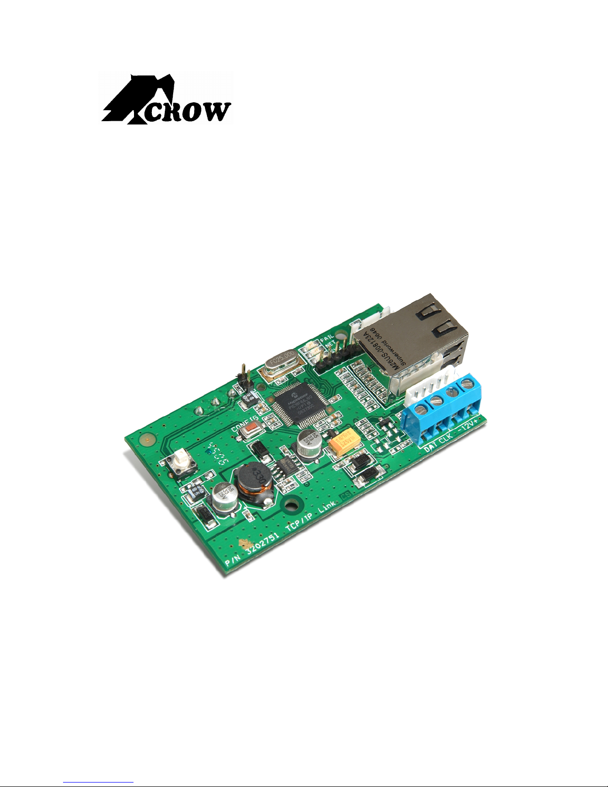
Runner Link
Gateway
ADD-ON INTERNET ALARM COMMUNICATION BOARD (TCP/IP)
Installation and Programming Guide
P/N 7111751 March 2007
Page 2

Crow Limited Warranty
(Crow) warrants this product to be free from defects in materials and workmanship under normal use and
service for a period of one year from the last day of the week and year whose numbers are printed on the
printed circuit board inside his product.
Crow’s obligation is limited to repairing or replacing this product, at its option, free of charge for materials or
labor, if it is proved to be defective in materials or workmanship under normal use and service. Crow shall
have no obligation under this Limited Warranty or otherwise if the product is altered or improperly repaired
or serviced by anyone other then Crow.
There are no warranties, expressed or implied, of merchantability or fitness for a particular purpose or
otherwise, which extend beyond the description on the face hereof. In no case shall Crow be liable to anyone
for any consequential or incidental damages for breach of this or any other warranty, expressed or implied,
or upon any other basis of liability whatsoever, even if the loss or damage is caused by Crow’s own
negligence or fault.
Crow does not represent that this product can not be compromised or circumvented; that this product will
prevent any person injury or property loss or damage by burglary, robbery, fire or otherwise; or that this
product will in all cases provide adequate warning or protection. Purchaser understands that a properly
installed and maintained product can only reduce the risk of burglary, robbery or other events occurring
without providing an alarm, but it is not insurance or a guarantee that such will not occur or that there will
be no personal injury or property loss or damage as a result. Consequently, Crow shall have no liability for
any personal injury, property damage or any other loss based on claim that this product failed to give any
warning. However, if Crow is held liable, whether directly or indirectly, for any loss or damage arising under
this limited warranty or otherwise, regardless of cause or origin, Crow’s maximum liability shall not in any
case exceed the purchase price of this product, which shall be the complete and exclusive remedy against
Crow.
© 2007. All rights reserved.
Information in this document is subject to change without notice. No part of this document may be
reproduced or transmitted in any form or by any means, electronic or mechanical, without express written
permission of
Print Version 016
Page 3

Contents
INTRODUCTION...........................................................................................................................1
SYSTEM OVERVIEW .......................................................................................................................1
BENEFITS ...................................................................................................................................2
HOW IT WORKS ...........................................................................................................................2
Customers Premises .................................................................................................................... 2
Monitoring Service Provider .........................................................................................................3
SHIPPING CONTENTS .....................................................................................................................4
Hardware ......................................................................................................................................4
Software........................................................................................................................................ 4
INSTALLING THE UNIT................................................................................................................5
INSTALLING THE SOFTWARE ............................................................................................................5
Installing the Installer Configuration Software.............................................................................. 5
INSTALLING THE HARDWARE............................................................................................................5
Connecting Cables ....................................................................................................................... 6
CONFIGURING THE RUNNER LINK..............................................................................................8
CHANGING THE PC IP ADDRESS TO THE INITIAL SETTING........................................................................8
CHANGING TO THE AUTHORIZED PC IP ADDRESS ................................................................................10
SETTING THE BOARD TO THE FACTORY DEFAULT IP ADDRESS.................................................................12
UPLOAD/DOWNLOAD PROGRAM (VIRTUAL KEYPAD) ..............................................................13
USING THE VIRTUAL KEYPAD .........................................................................................................13
Initiating Communication with the Unit ....................................................................................... 15
Example 1 - Taking Control of the Unit (Alarm/Disarm) ............................................................. 17
Example 2 - Changing the Password (Installer Mode)............................................................... 19
Example 3 - Changing the Phone Number................................................................................. 21
INSTALLING THE RECEIVER SERVER CONFIGURATION PROGRAM .........................................22
i
Page 4
Introduction
The RUNNER LINK Gateway is a small external hardware addition to Crow’s
Runner Control Panel Series. It is connected to the Alarm System using a special
cable supplied and also connected to the Internet or LAN using the standard
RJ-45 connector.
Today the majority of businesses and domestic households that have an intruder
alarm installed already have an open connection to the Internet. The RUNNER
LINK Gateway connects itself to the LAN therefore establishing a very low cost
communication link with any Monitoring Service of their choice.
When connected to a central monitoring station over the Internet the alarm
system has the ability to ensure professional protection 24/7. This is because a
watchdog timer ensures that the communication link from the control panel to
the central monitoring station is always intact and if there is a break in
communication an alarm is triggered immediately to cause an alarm.
When you are connected to a Monitoring Service you are able to get them to send
commands and send you a status report of your Alarm System whenever you
ask. For example, arm or disarm your Alarm System using the Internet
connection.
System Overview
1
Page 5

RUNNER LINK Gateway Introduction
Benefits
Connecting intruder alarm equipment to the Internet
Supporting standard alarm protocols (SIA/CID)
Dedicated servers for secure polling
Real-time remote access to the system for the alarm owner (virtual keypad)
Event log on demand
Add-on Internet gateway from Runner Series control panels
Continuous line supervision
Alarm signals transmitted via the Internet to remote PCs or Central station
Uploading and downloading software for showing status and sending commands
over the Internet
Back-up line using GPRS (option)
Distribution of messages triggered by alarms to cellular and emails
How it Works
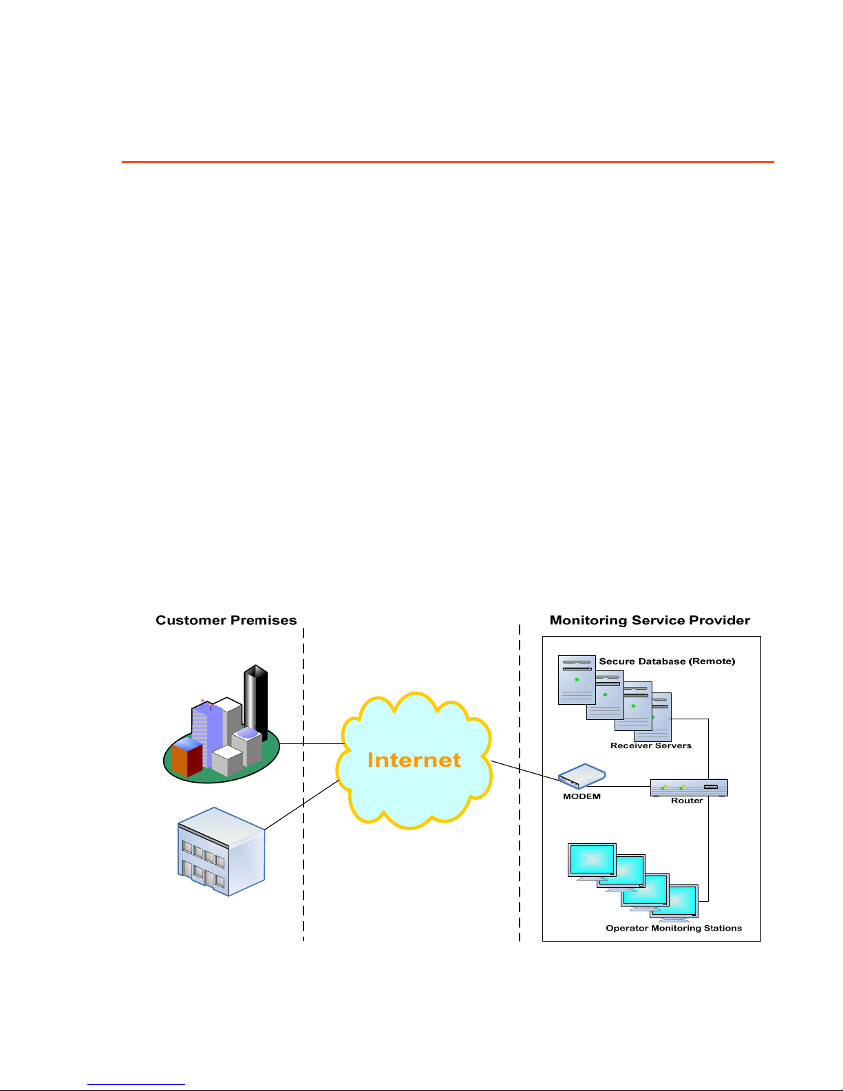
The events from your alarm system are automatically transferred via the
RUNNER LINK Gateway to a remote dedicated server located on the secure and
tamper proof premises of your Monitoring Service Provider.
When an alarm is triggered on your premises the signal is immediately received
on one of the many monitoring stations. Depending on how you have configured
the system the alarm can propagate the alarm via SMS messaging and voice
messages to multiple recipients. At the same time the operator can intervene and
escalate the alarm if required.
The RUNNER LINK Gateway is a true Plug & Play device and only has to be
connected to the bus of an existing alarm controller.
Customers Premises
Any Crow Runner Alarm System version 9.03 or later is able to install the
RUNNER LINK Gateway. The installation is relatively minor as only two cables
are connected to the Runner Link box.
Bus cable
The bus cable is a special cable supplied with the Runner Link and connects the
unit to the controller.
Internet Connection Cable
Most domestic households and businesses today have an open connection to the
Internet. To take advantage of this fact there is an RJ-45 plug on the Runner Link
box that plugs directly into a router that is already connected to the Internet.
2
Page 6
RUNNER LINK Gateway Introduction
Monitoring Service Provider
The Monitoring Service Provider is located in a tamper proof environment and
uses multiple redundant secure receiver servers.
Redundancy means that the servers take over from one another if one fails.
When the repaired server is put back online it automatically updates itself with
any new information from the working servers until it is synchronized.
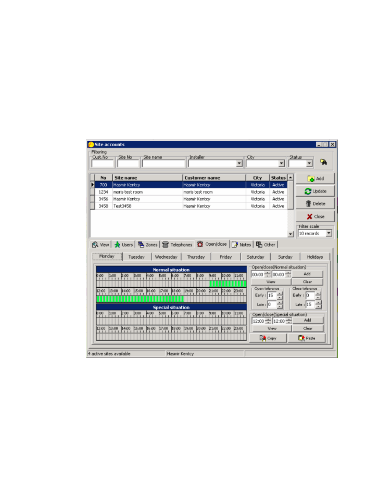
Monitoring Software Tools
It is recommended that you choose a service provider that uses modern
sophisticated software tools and able to monitor your alarm system events.
An example of one of the basic A-Traq screens
3
Page 7
RUNNER LINK Gateway Introduction
Shipping Contents
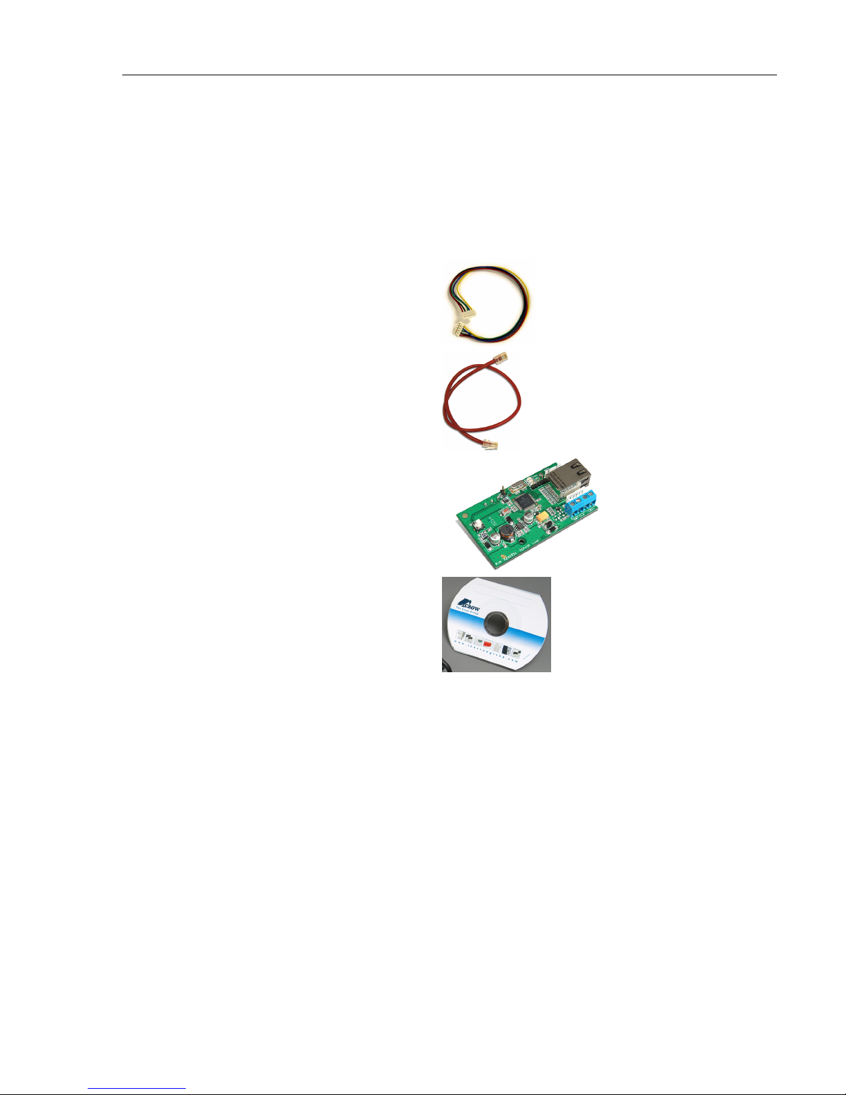
Hardware
RUNNER LINK Gateway module
RJ-45 Ethernet cross Cable
Fast Bus connection cable
Software Installation CD
Bus cable
RJ-45 Ethernet (LAN) cable
Software
There are two software installation files on the CD:
IP Link.exe
This file contains two programs and when installed places two icons on your
Desktop.
IP Configuration (Runner Link) – This program is used by the installer to setup
Upload Download (Virtual Keypad) – enables someone to use it as a remote
ReveiverServer.exe
This is a service that must be installed on the Receiver Servers at the premises
of the Monitor Service Provider.
For details see
page
Runner Link board
Installation CD
the unit in the field
Internet keypad to access your Alarm System
Installing the Receiver Server Configuration Program on
22.
4
Page 8
Installing the Unit
Installing the Software
Installing the Installer Configuration Software
Installing the Runner Link™ On your PC
This software program enables the installer to configure the Runner Link unit in
the field.
1. Place the installation CD in your CD reader.
2. Copy the IP Link.exe file onto your PC and then double click it.
3. Ensure that you now have both the
(Upload Download.exe) icons displayed on your Desktop.
Installing the Hardware
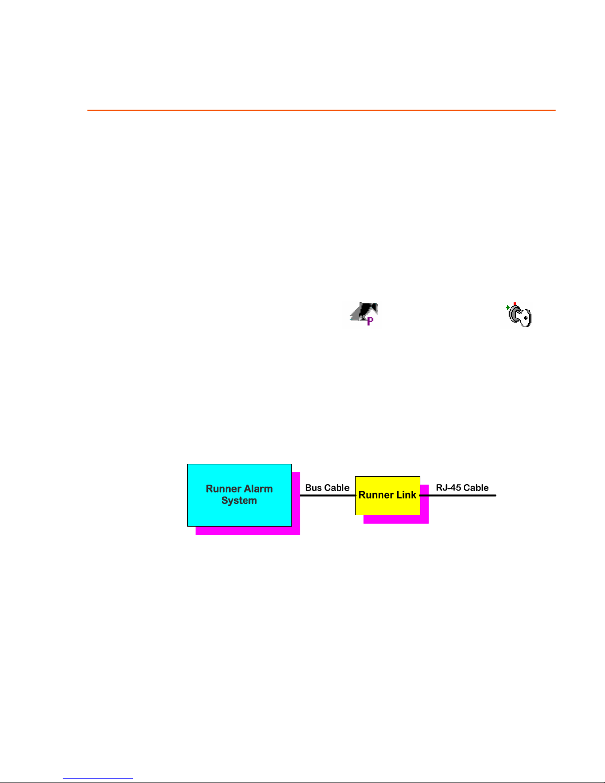
The Runner Link unit is shipped inside a protective plastic box and is connected
with two cables.
The Bus cable connects unit to the Runner alarm system
The RJ-45 cable connects the unit to the LAN or WAN
Figure 1 Cable Connection Diagram
(Pconfig.exe) and the
5
Page 9
RUNNER LINK Gateway Installing the Unit
Connecting Cables
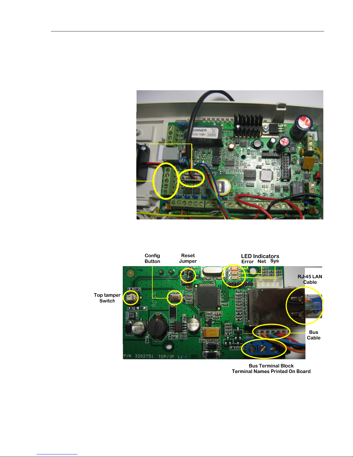
1. Connect one end of the bus cable to the bus on the control panel main board.
You can also use the bus terminal block to connect the bus using discrete
wires, see
Install the cable
in any free Bus
socket
Bus Terminal Block
Top Terminal is Not
Used (LIN)
Figure 4 on page 7.
Figure 2 Main Board Bus Connection
2. Connect the RJ-45 LAN cable to the Runner Link board as shown in
Figure 3.
and
Figure 3 Runner Link Board Connections and Locations
Figure 2
6
Page 10
RUNNER LINK Gateway Installing the Unit
Table 1 LED Description Table
LED Description
Fail Solid Red when pressing the Config button or when there is an error.
Net Solid green when finding the network.
Sys Blinks green when the bus is active.
3. Connect the other end of the Bus cable onto the board as shown in Figure 3.
Power is supplied to the board via the Bus cable and the red LED is lit.
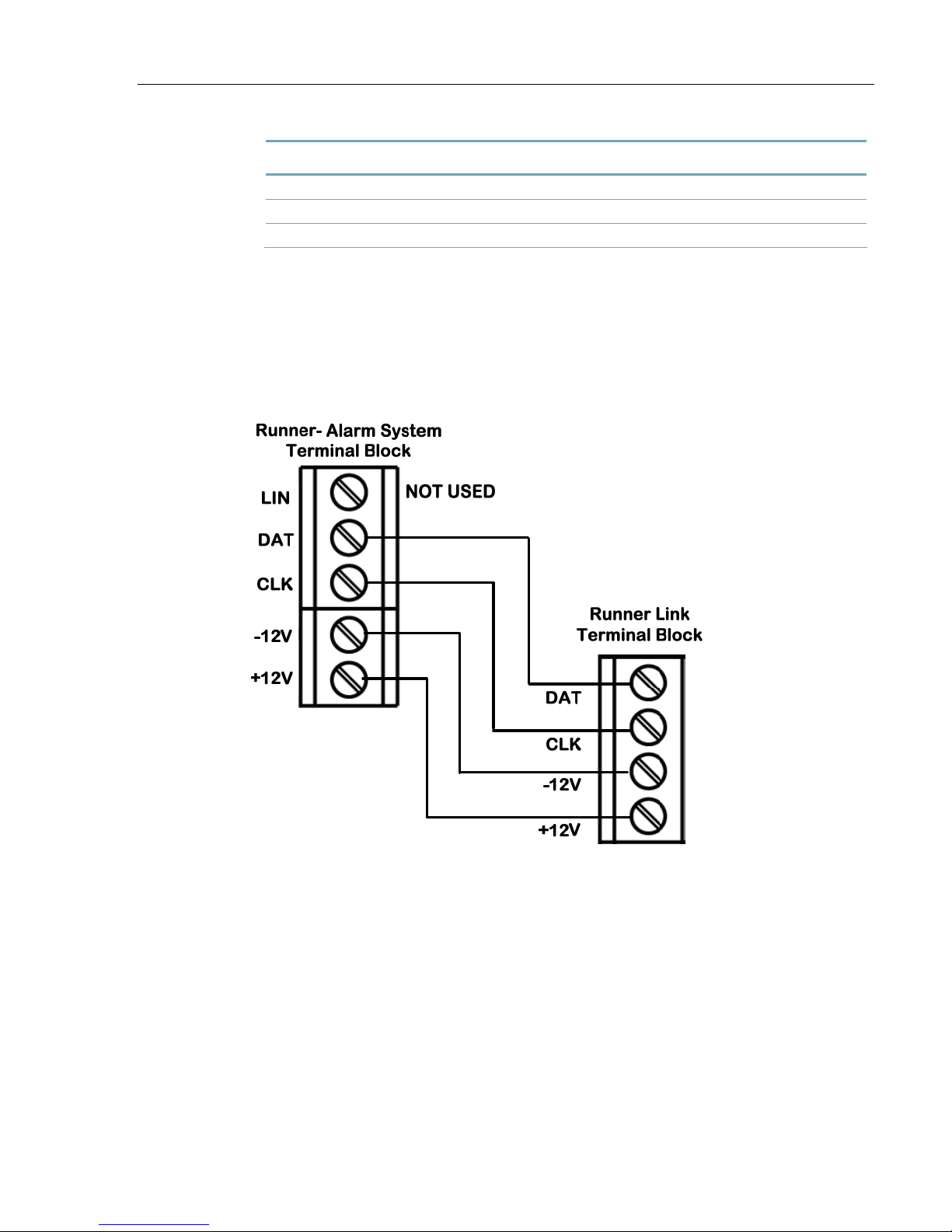
Using the Bus Terminal Block
You can also connect discrete wires as shown in the figure below. See also Figure
2 and
The LIN terminal is NOT used.
Figure 3.
7
Figure 4 Using the Bus Terminal Block
Page 11
Configuring the Runner Link
In order to configure the Runner Link you must first communicate with it using
the initial setup IP of 192.168.0.5 and a Subnet Mask of 255.255.255.0.
These are the factory defaults.
Changing the PC IP Address to the Initial Setting
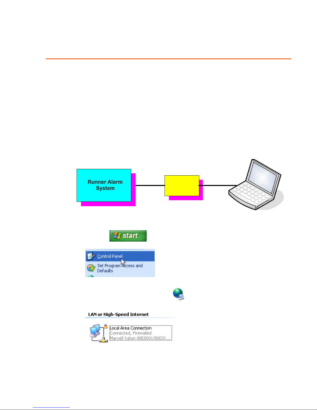
To perform the initial communication with the Runner board connect the cables
as shown in the diagram below.
Installer PC/Laptop
Bus Cable
Figure 5 Installer Cable Connections
1. Click the button
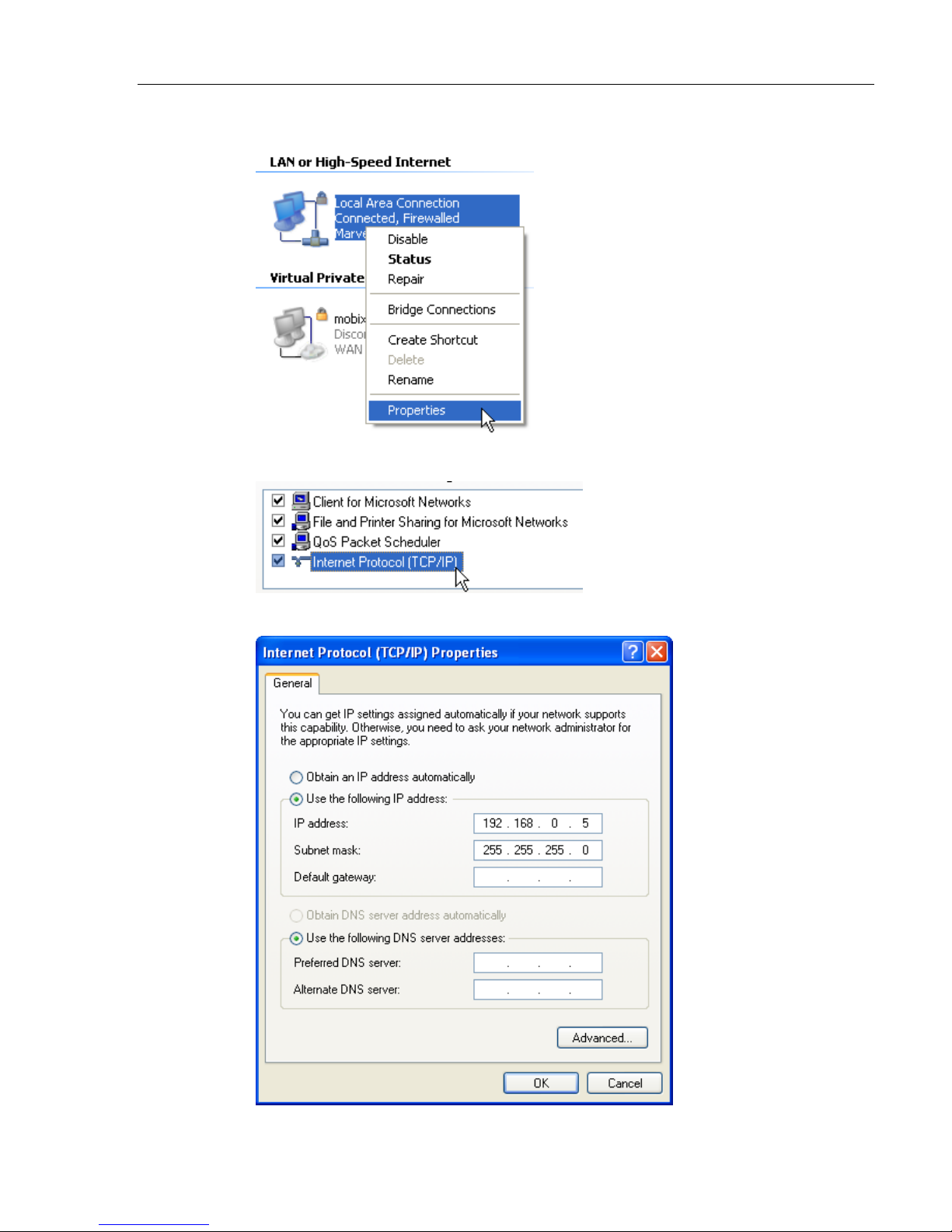
2. Click Control Panel.
3. Click the Network Connections
RJ-45 Cross
Cable
Runner Link
icon.
8
Page 12
RUNNER LINK Gateway Configuring the Runner Link
4. Right-click the active Local Area Connection icon
5. Click Properties.
6. Double-click Internet Protocol (TCP/IP).
9
Page 13
RUNNER LINK Gateway Configuring the Runner Link
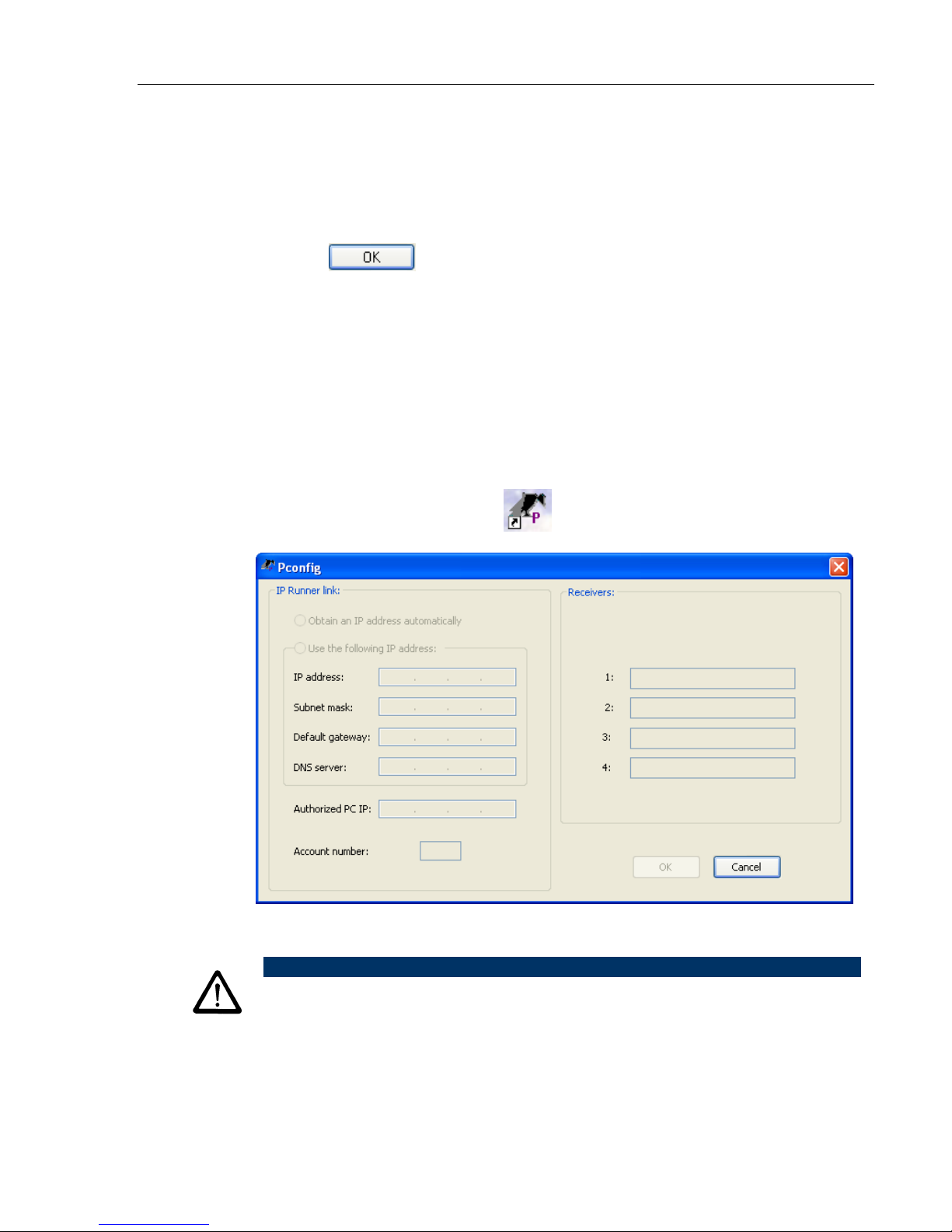
7. Select Use the following IP address radio button.
8. Enter an IP address of 192.168.0.5.
9. On the PC keyboard, press the [Tab] key, or click the Subnet Mask field
(underneath the IP address).
A value of 255.255.255.0 is inserted automatically.
10. Click the
button twice and close the open screens.
Changing to the Authorized PC IP Address
This section requires that you have already installed the Configuration software.
Installing the Installer Configuration Software on page 5.
See
The Authorized Address is the name given to the IP address of your computer
that you use for configuring the alarm systems. It is a static address of your
choosing and makes maintaining the equipment you have installed much easier.
1. Ensure that the PC you are using to change the IP address has been set to
192.168.0.5 and a Subnet Mask of 255.255.255.0.
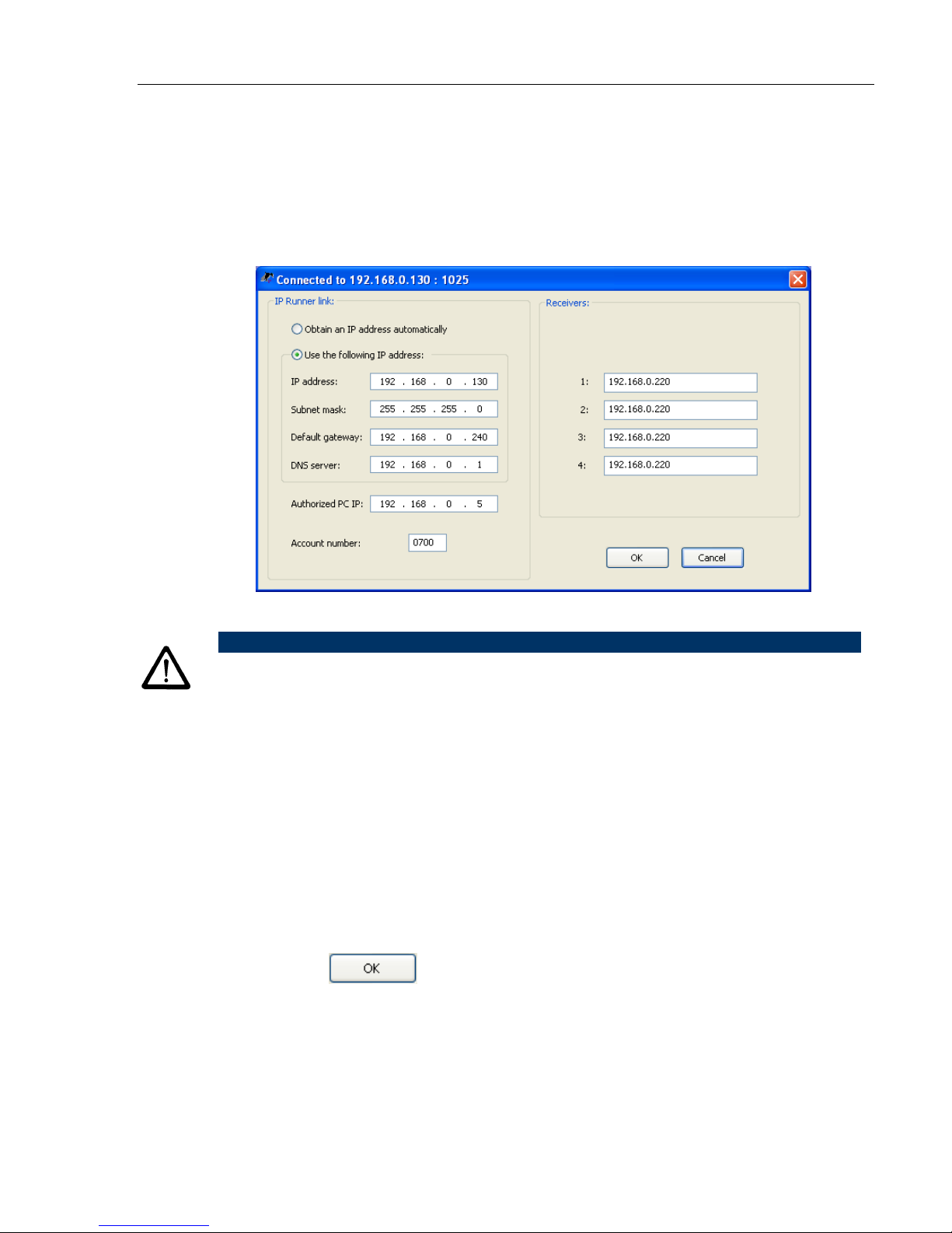
2. Double-click the Configurator
icon.
The Pconfig screen opens.
NOTE
For security concerns the screen and CONFIG button are disabled after
approximately 45 seconds. To continue, close the screen and open the
program again.
10
Page 14
RUNNER LINK Gateway Configuring the Runner Link
3. On the Runner Link board, press the Config button for minimum of 3
seconds.
The red FAIL LED lights and then after 3 seconds the green NET LED lights
as well and the green SYSTEM LED starts to blink. There is an audible beep
from your PC (acknowledgment) and the FAIL and NET LEDS turn off. The
screen then is populated with the default IP addresses from the board.
4. Change the Authorized PC IP address to the normal working IP of your PC.
NOTE
This IP address MUST be used for maintaining the alarm system.
5. In the IP Runner link pane, select the radio button required for the network
the Runner Link is connected to.
If a static address is needed all the required information must be entered
manually.
6. In the Receiver pane, change the IP addresses of the Receiver servers to
those of the Monitor Service Provider.
7. Enter the correct account number given by the Service Provider so that the
unit can be found rapidly when the operator needs to contact it.
The Monitor Service Provider is able to contact the unit by using the Account
number, which is the actual address of the unit.
8. Click the
The screen closes and only the green SYS LED continues to blink. The other
two LEDS are OFF.
9. Set the IP of your laptop back to your normal working IP.
10. Disconnect the cross cable from the Runner Link and connect the Runner Link
to the LAN or WAN.
button.
11
Page 15
RUNNER LINK Gateway Configuring the Runner Link
Setting the Board to the Factory Default IP Address
1. Using Figure 3 on page 6 as a guide, short the Reset jumper pins using the
jumper installed on one of the pins.
2. Press the CONFIG button.
The board is now reset to the factory defaults.
NOTE
You can also reset the Runner Link by turning on power to the
board when the pins are shorted using the jumper. You can then
remove the jumper and plug it onto one of the pins for safe
keeping.
12
Page 16
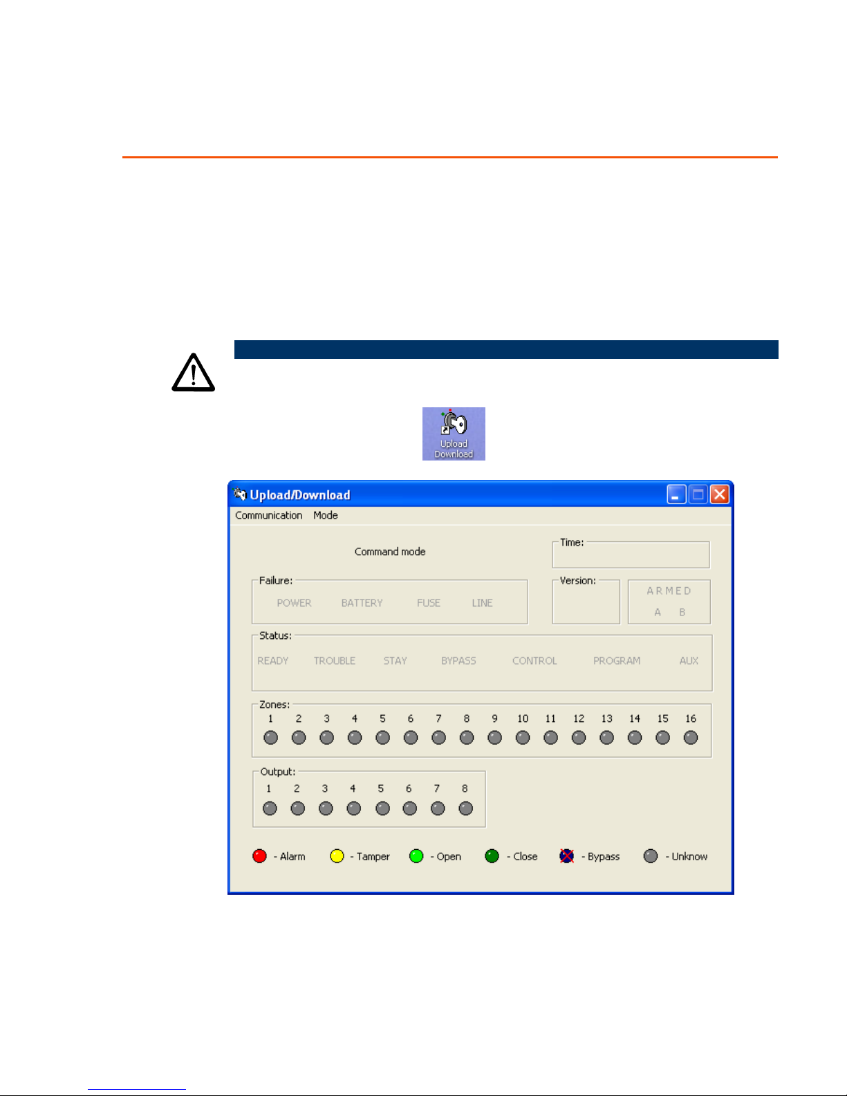
Upload/Download Program (Virtual Keypad)
The program enables the Monitoring Service Provider to control your Alarm
System in real time over the Internet.
Using the Virtual Keypad
NOTE
This program can only be used after configuring the Runner Link.
1. From the desktop, click the icon.
13
Page 17
RUNNER LINK Gateway Upload/Download Program (Virtual Keypad)
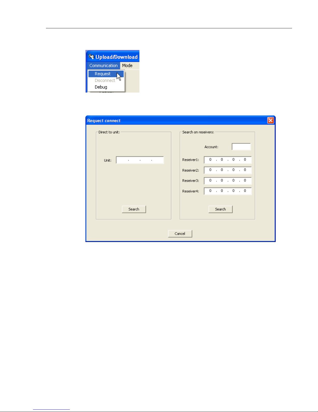
2. Click the Communication menu.
3. Click Request.
There are two ways to communicate with the unit (See Below)
14
Page 18
RUNNER LINK Gateway Upload/Download Program (Virtual Keypad)
Initiating Communication with the Unit
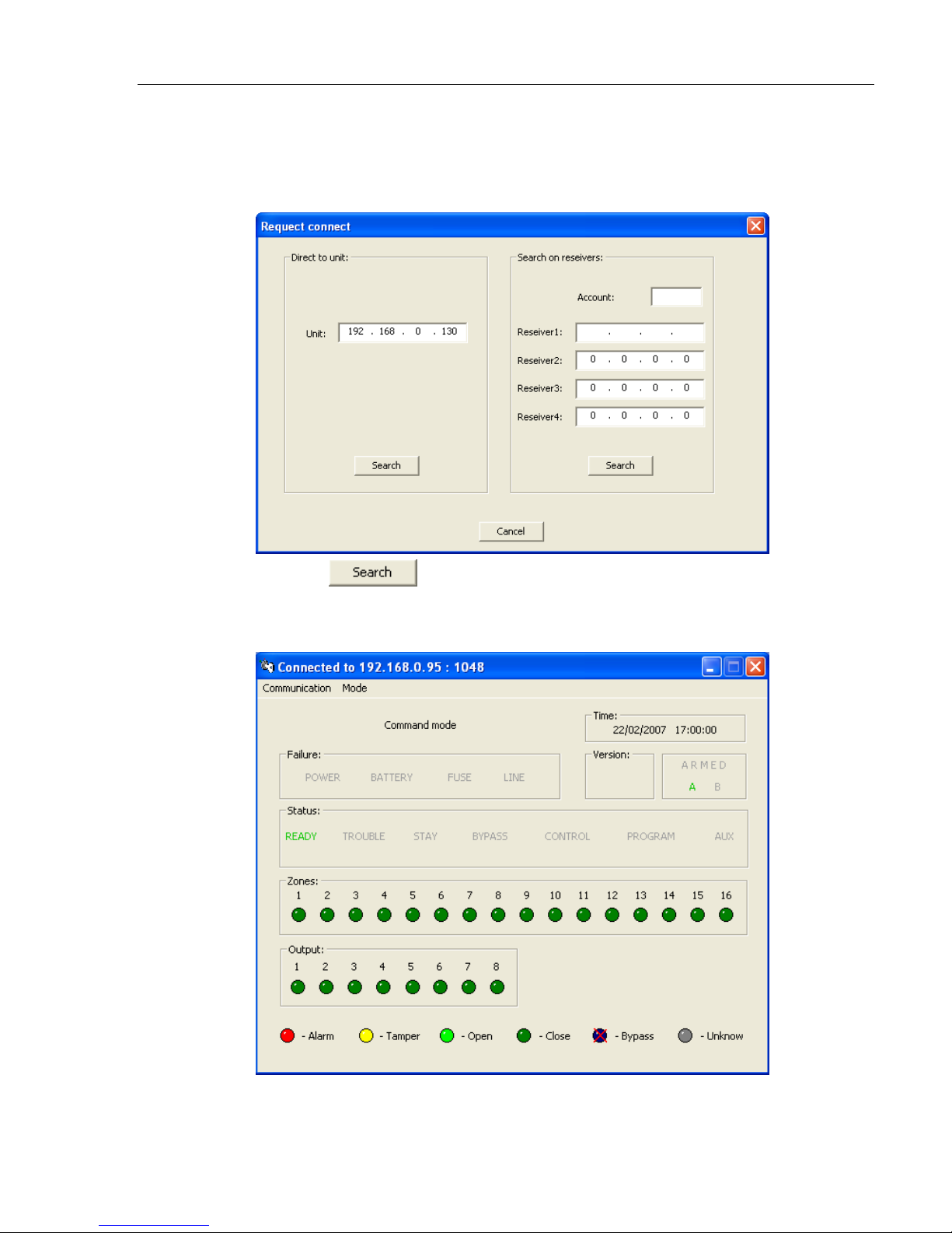
Using the Unit IP Address
1. In the Direct to unit pane, enter the unit IP.
2. Click the
button.
3. ONLY if the connection to the Alarm System is successful is the following
screen displayed.
You are now connected to the Alarm System.
15
Page 19
RUNNER LINK Gateway Upload/Download Program (Virtual Keypad)
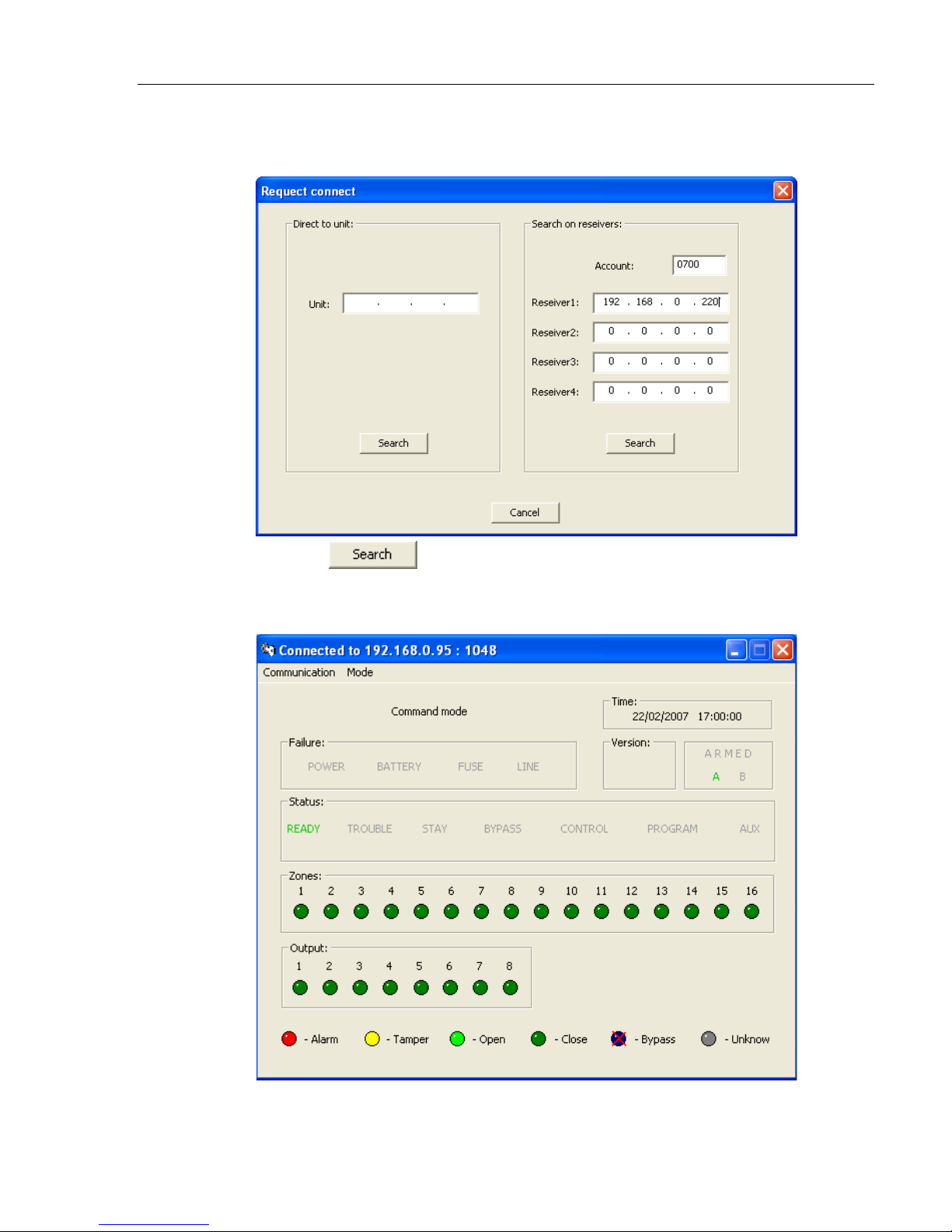
Using the Account Number and Receiver Server IP Address
1. In the Search for Receivers pane, enter the account number and at least
one receiver IP address.
2. Click the
button.
3. ONLY if the connection to the Alarm System is successful is the following
screen displayed.
You are now connected to the Alarm System.
16
Page 20
RUNNER LINK Gateway Upload/Download Program (Virtual Keypad)
Example 1 - Taking Control of the Unit (Alarm/Disarm)
NOTE
Using this program you can perform the same functions as if you were
using the keypad (local) connected to the Alarm System. Below you
will find examples on how this is achieved...
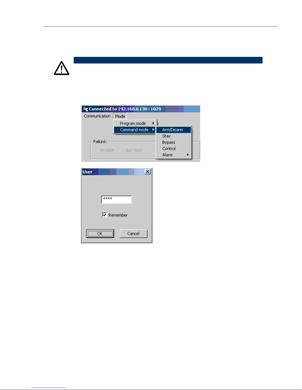
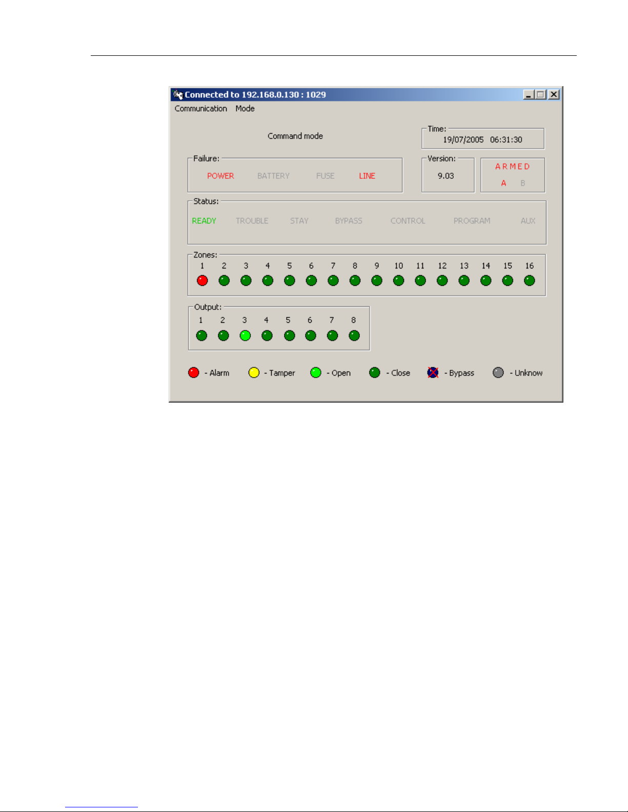
1. Click the Mode menu, Command mode and then click Arm/Disarm.
The User password window opens
2. Enter the password.
The default User password is 1234.
This password allows limited access only. If you need complete access, see
installer password,
Mode) on page
17
Example 2 - Changing the Password (Installer
19.
Page 21
RUNNER LINK Gateway Upload/Download Program (Virtual Keypad)
For information on how to configure the unit, see the Upload/Download manual
via PSTN.
18
Page 22
RUNNER LINK Gateway Upload/Download Program (Virtual Keypad)
Example 2 - Changing the Password (Installer Mode)
This section explains how to change the password.
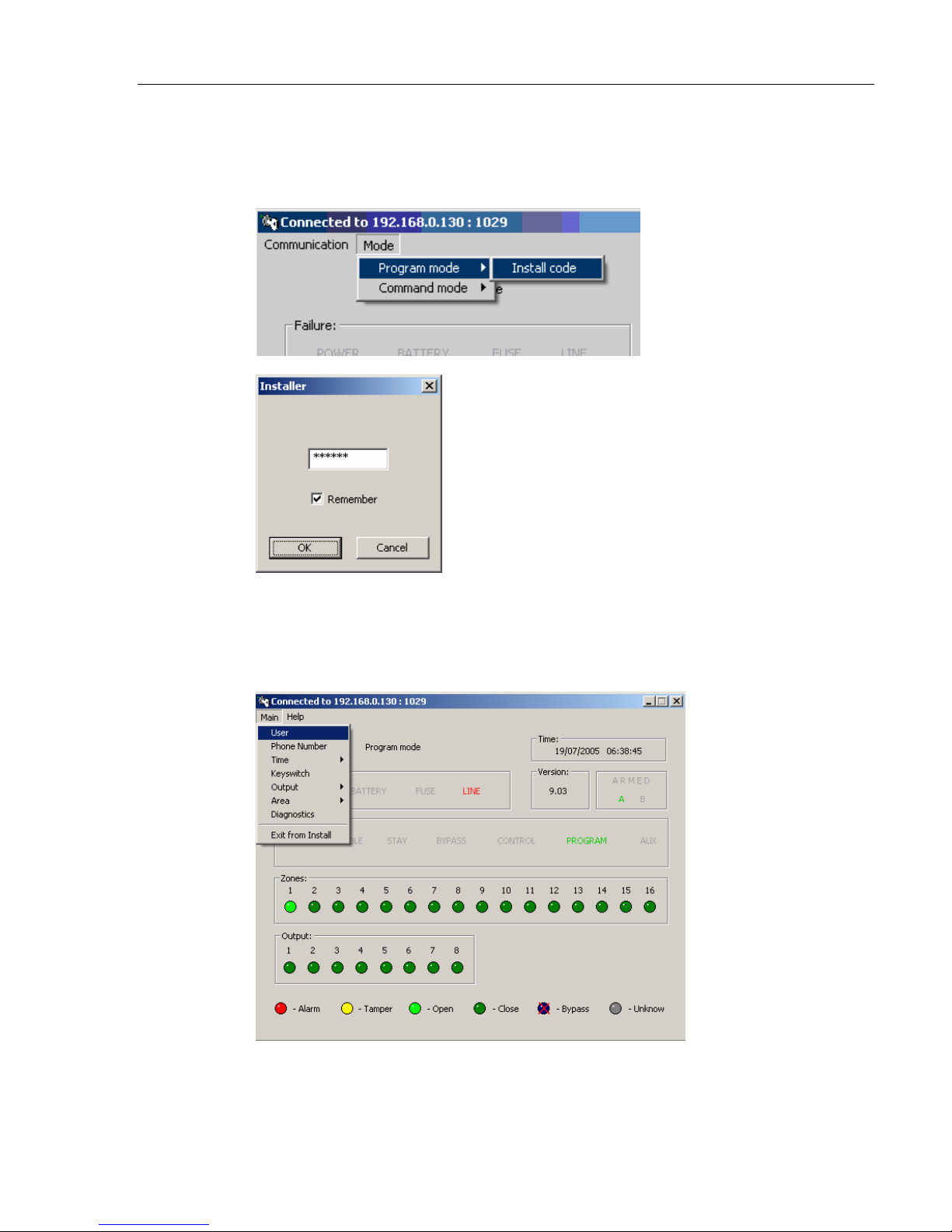
1. Click the Mode menu, Program mode and then click Install code.
The Installer password window opens
2. Enter the installer password
The default installer password is 000000 (six zeros) and gives full access.
The User screen is shown above with the Main menu open.
3. Click the Main Menu and click Exit from Install.
19
Page 23
RUNNER LINK Gateway Upload/Download Program (Virtual Keypad)
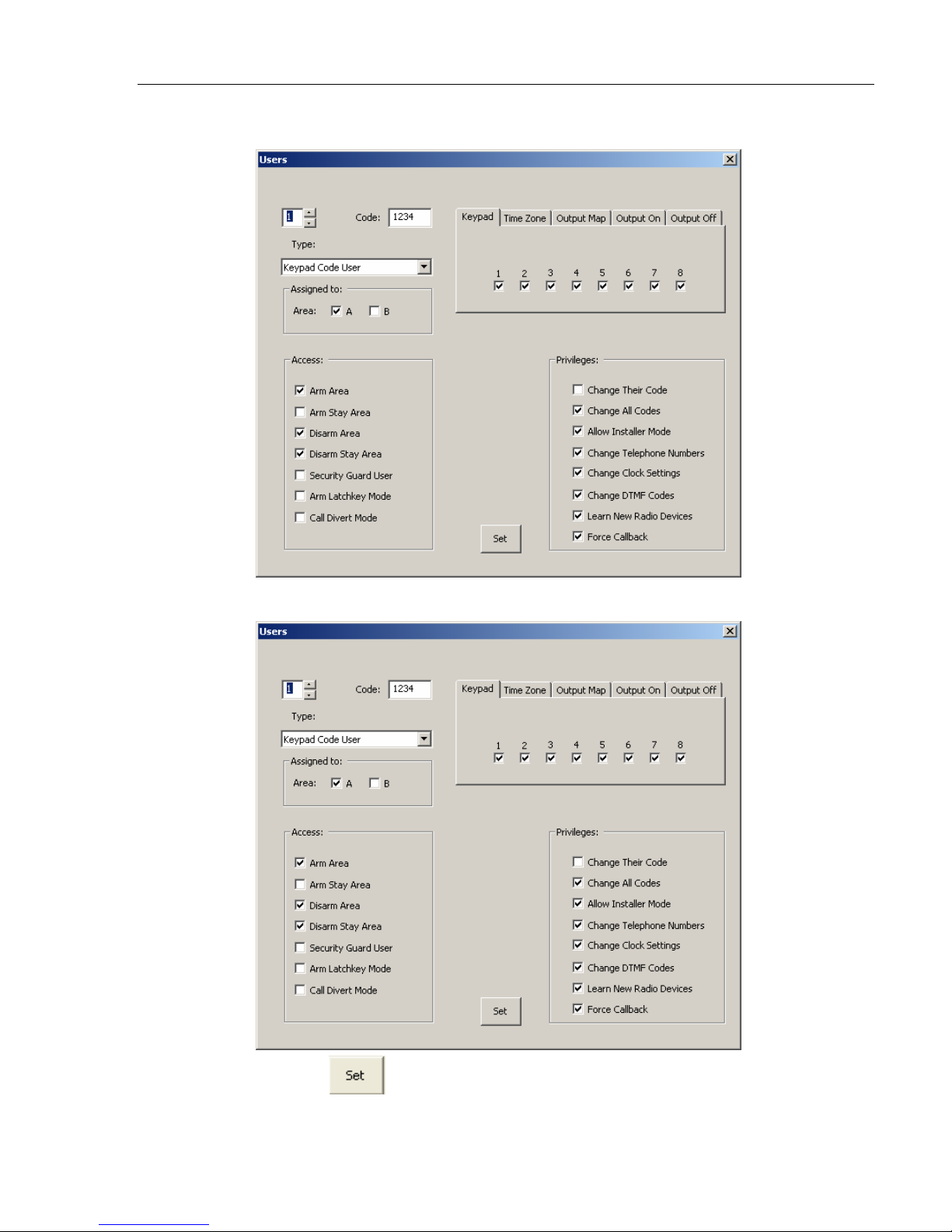
4. Click Users.
5. In the Code field (password), enter a new password.
6. Click the
20
button.
Page 24
RUNNER LINK Gateway Upload/Download Program (Virtual Keypad)
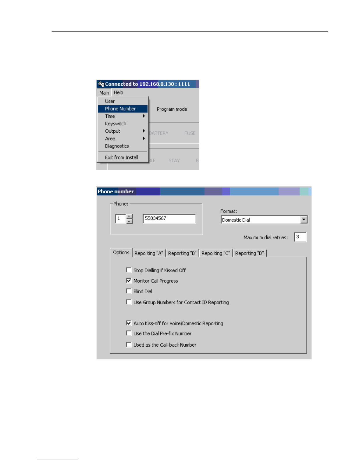
Example 3 - Changing the Phone Number
This section explains how to change the phone number.
1. Click the Main menu.
2. Click Phone Number.
21
Page 25
Installing the Receiver Server Configuration
Program
NOTES
The Receiver servers are installed on the premises of the Monitor
Service Provider.
This program must be installed once on each of the servers in
order to maintain communication with the units in the field. This is
the actual service and must run continuously whenever the server
is powered on
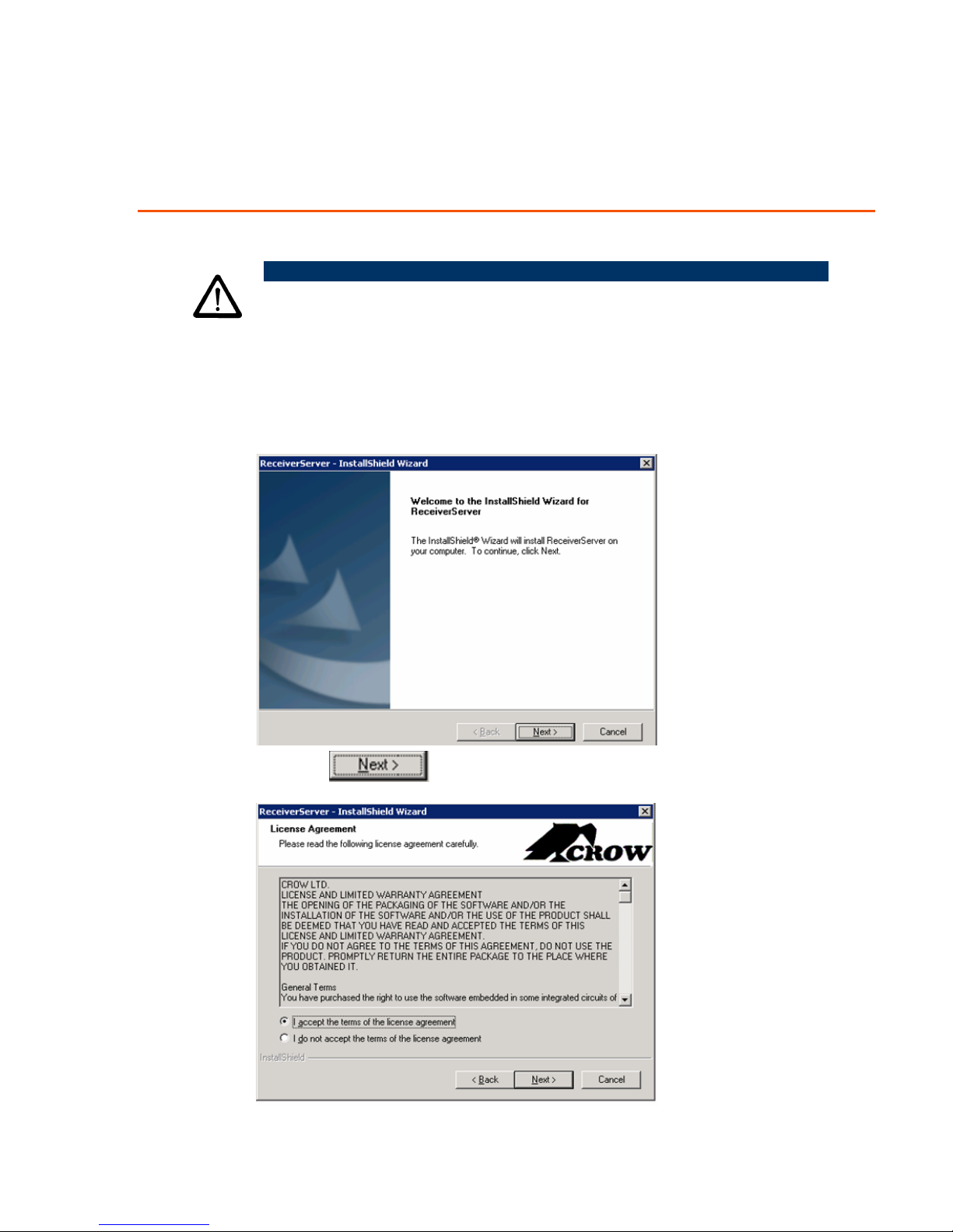
1. On the installation CD, double-click the ReceiverServer.exe file.
2. Click the
22
button.
Page 26
RUNNER LINK Gateway Installing the Receiver Server Configuration Program
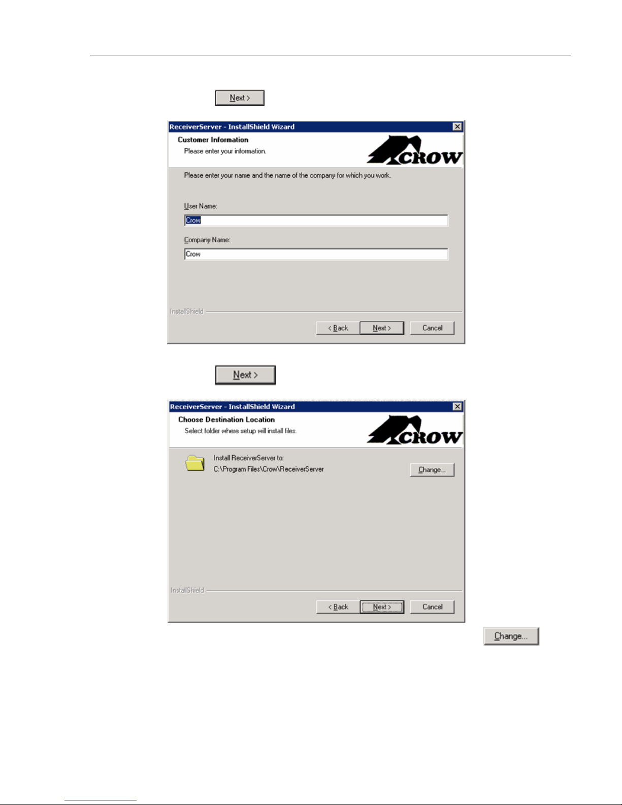
3. Select the "I accept" the terms of the license agreement radio button.
4. Click the
button.
5. Enter a user name and the name of the company.
6. Click the
button.
7. If you want to change the default installation folder, click the
button and select another folder.
23
Page 27
RUNNER LINK Gateway Installing the Receiver Server Configuration Program
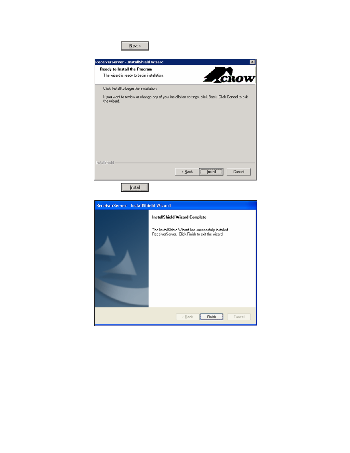
8. Click the
9. Click the
button.
to install the program.
24
Page 28
RUNNER LINK Gateway Installing the Receiver Server Configuration Program
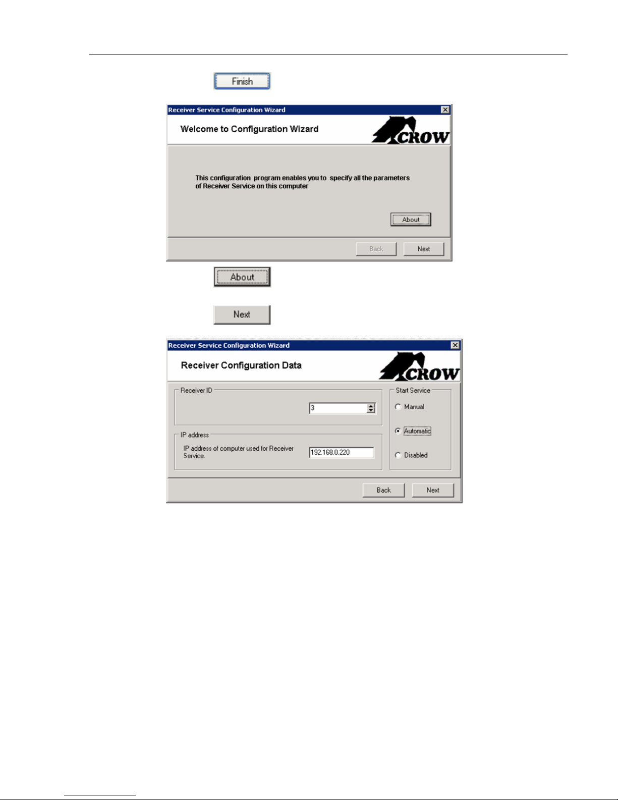
10. Click the
11. Click the
does.
12. Click the
button to exit the wizard.
button to get a brief description on what this program
button.
13. Enter the Receiver Server IP address and the ID number.
Give the ID numbers in the same sequence as the IP addresses so that it is
easier to remember them.
14. In the Start Service pane, select either Manual, Automatic or Disable.
Manual - requires that you start the service manually.
Automatic – the service is started automatically when the program opens.
Disable – puts the server offline so that it cannot be accessed.
25
Page 29
RUNNER LINK Gateway Installing the Receiver Server Configuration Program
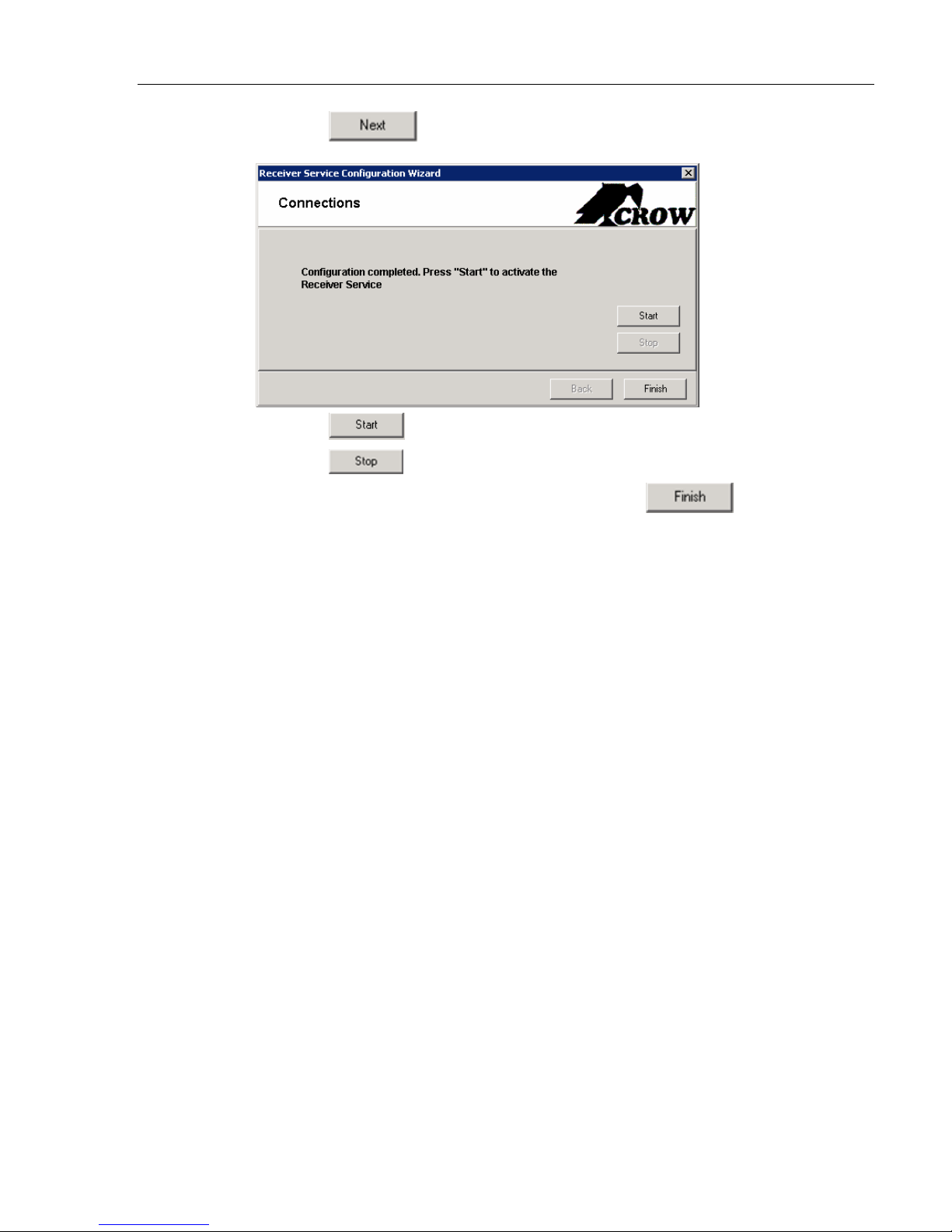
15. Click the
button.
16. Click the
17. Click the
button to start the service.
button to stop the service.
18. If you have stopped the server, you can click the
the window and the program.
button to close
26
 Loading...