

Page 1
ELECTRONIC ENGINEERING LTD.
1
2
3
4
A
5
6
7
8
B
Ready-Byp
System
Trouble
Program
7
4
1
2
3
5
6
9
8
0
ENTER
PROGRAM
BYPASS
STAY
ARM
CONTROL
MEMORY
PANIC
PowerWave – 8
8 Zone Control Panel Communicator
Installation and
Programming Guide
P/N 7111260 Rev. H N.A
Version 8.72 01/2004
Page 1
Page 2

CONTENTS
CONNECTION DIAGRAM ..........................................................................3
INPUTS .....................................................................................................4
OUTPUTS ................................................................................................. 5
TELECOM INTERFACE .............................................................................6
KEYPADS OPTIONS .................................................................................7
KEYPAD INSTALLATION ........................................................................... 8
MEMORY VIEWING MODE ........................................................................9
KEYPAD ADDRESS ASSIGNMENT .......................................................... 10
KEYPAD FUNCTIONS ............................................................................. 11
INSTALLING RX-4 0 RADIO RECEIVER ................................................... 11
ACCESSING & EXITING PROGRAM MODES ........................................... 12
USER CODE P ROGRAMMING.................................................. .................. 13
USER CODE OPTIONS............................................... ................... .............. 14
OUTPUT OPTION PROGRAMMING ......................................................... 14
ZONE ALARMS TO OUTPUTS ................................................................. 16
MONITOR ALARMS TO OUTPUTS ..........................................................16
24 HOUR ALARMS TO OUTPUTS ............................................................16
DAY ZONES TO OUTPUTS ..................................................................... 17
ZONE TAMPER ALARMS TO OUTPUTS .................................................. 17
RADIO PENDANTS TO OUTPUTS ........................................................... 17
TEMPORARY OUTPUT DISABLE ............................................................ 18
AREA “A” OPTIONS ................................................................................ 18
AREA “A” OUTPUT OPTIONS .................................................................. 19
AREA “B” OPTIONS .................................................................................20
AREA “B” OUTPUT OPTIONS .................................................................. 20
ZONE EOL OPTIONS .............................................................................. 21
ZONE PROGRAM OPTIONS .................................................................... 22
ZONE INACTIVITY TIMER ....................................................................... 24
ENTRY DELAY TIMES ............................................................................. 24
EXIT DELAY TIMES...........................................................… ....................... 24
TWO TRIGGER TIMER.........................................................… .................... 24
DAY MODE TIMER TO KEYPAD BUZZER ................................................ 24
OUTPUT TIMING OPTIONS ..................................................................... 25
LOADING RADIO ZONES ........................................................................ 26
RADIO ZONE OPTIONS .......................................................................... 26
LOADING RADIO PENDANTS ..................................................................27
RADIO PENDANT OPTIONS “A” .............................................................. 28
RADIO PENDANT OPTIONS “B” .............................................................. 28
KEYPAD PARTITION ASSIGNMENT........................................................… . 29
KEYPAD PANIC BUTTON ENABLE/OPTIONS .......................................... 29
KEYPAD FIRE BUTTON ENABLE/OPTIONS ............................................ 30
KEYPAD MEDICAL BUTTON ENABLE/OPTIONS ..................................... 30
MISCELLANEOUS PANEL OPTIONS.#1....................................................... 31
MISCELLANEOUS PANEL OPTIONS.#2........................................ ............. 32
DURESS DIGIT ....................................................................................... 33
SETTING THE REAL TIME CLOCK .......................................................... 33
SETTING DAYLIGHT SAVING START/FINISH .......................................... 33
RESET DEFAULTS .................................................................................. 33
CLEAR MEMORY EVENT BUFFER .......................................................... 34
WALK-TEST MODE ENABLE ................................................................... 34
DATA TRANSFER UNIT(DTU) ................................................................. 34
DIALER PROGRAMMING OPTIONS ........................................................ 35
PHONE NUMBER PROGRAMMING & OPTIONS ...................................... 38
CONTACT ID REPORTING CODES ......................................................... 41
ACCOUNT CODE ................................................................................... 41
4+2 REPORTING CODES ........................................................................ 42
VOICE BOARD & DTMF CODE PROGRAMMING ..................................... 45
UPLOAD/DOWNLOAD SECURITY CODE ................................................46
AUTO-ANSWER RING COUNT & MAINS FAIL REPORT DELAY ............... 46
AUTOMATIC TEST REPORTING TIME PROGRAMMING .......................... 46
PROGRAM SUMMARY ............................................................................ 47
Page 2
Page 3
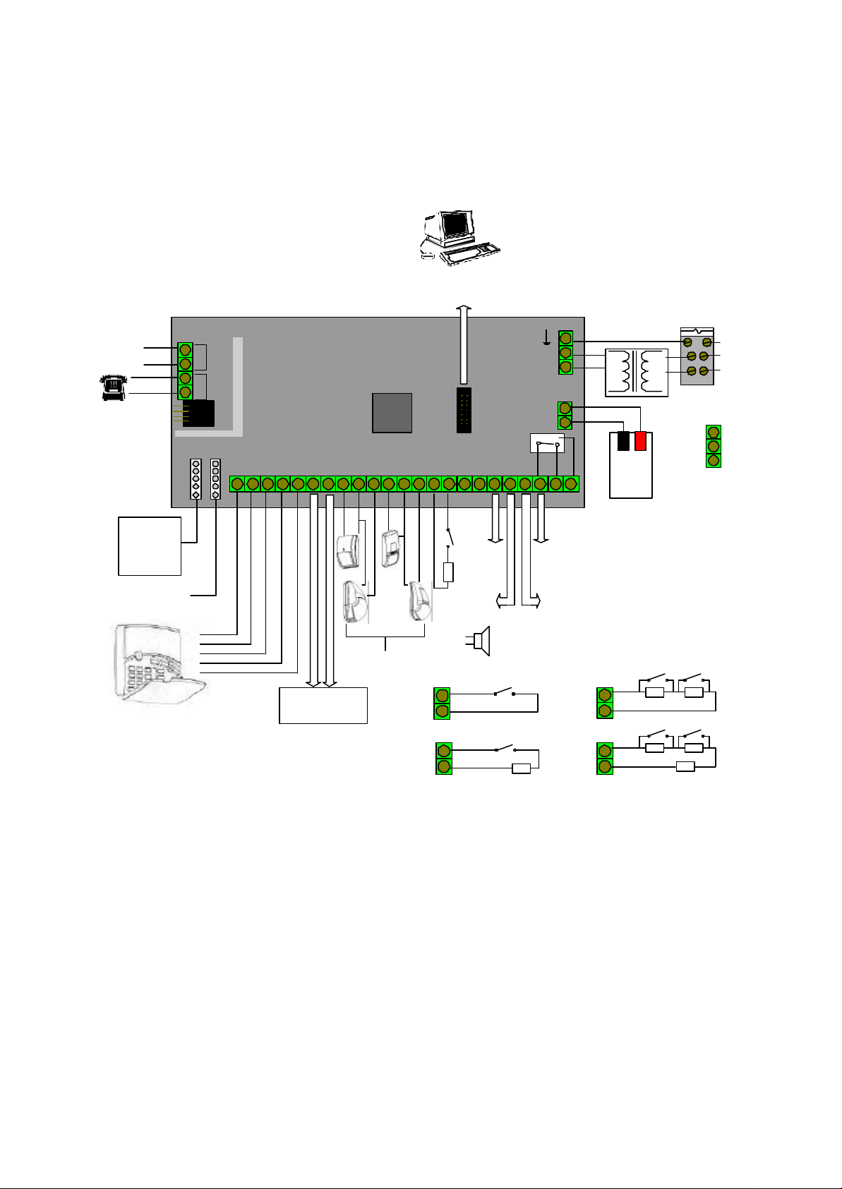
CONNECTION DIAGRAM
PC INTERFACE VIA
D-LINK / EXPANTION
CARD
MAIN FUSE
PHONE
IN
OPTIONAL
PHONE LINE
CONNECTOR
RX-40
RECIEVER
OPTIONAL
KEYPAD
CONN.
KEYPAD BUS
CONNECTION
EXT. KEYPADS
/ OUTPUT
BOARD
InOut
KEYPAD \
RECIEVER
Lin
Dat
Clk
Neg
12V
Pos
0V
POWER FOR
DETECTORS &
ACCESSORIES
2+6
1+5
0V
ZONE
DETECTORS
INPUTS
8.6X
3+7
0V
4+8
1+5
0V
1+5
0V
EXPANTION
Tmp
0V
2K2
12V
0V
OUT 1
1A max
& 12V
OUT 2
1A max
& 12V
ZONES 1-4
ZONES 1-4
1
AC 17V
AC 17V
243
2K2
BATTERY
Red
Blk
COM
NC
OUT 4
100mA max
& 12V
OUT 3
100mA max
& 12V
NO
1+5
1+5
0V
0V
BATT.
12V
8Ah
ZONE 1
ZONE 1
4K7
ZONE 5
8K2
ZONE 5
8K24K7
2K2
V
AC Input
100V - 230
Page 3
Page 4
INPUTS
The PW-8 has 5 separate programmable monitored analogue inputs,
4 x Programmable, multi-state detection inputs
1 x Programmable tamper input ( with optional Key-switch functions)
Each input must be terminated with short circuit or the appropriat e value of end-of-line resistors, even if the input
is unused.
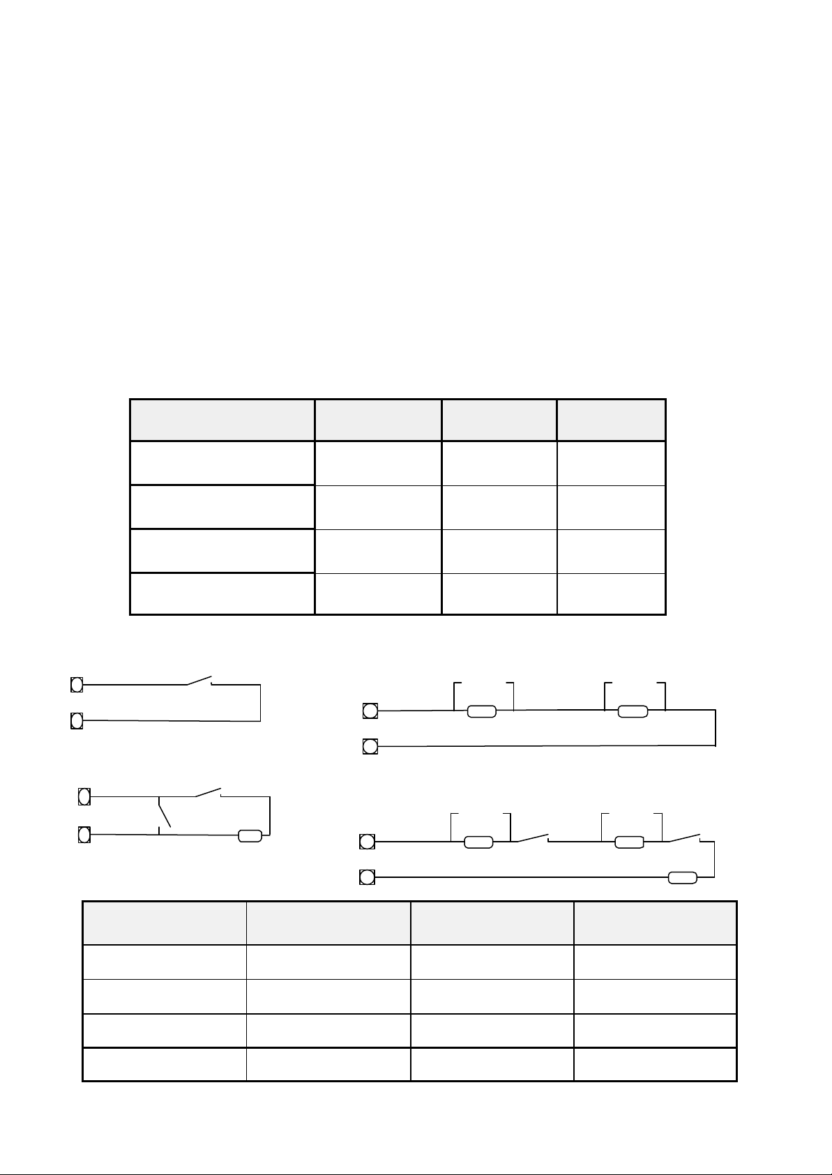
ZONE INPUTS - Each of the 4 zone inputs can be assigned one of the following configuration options
Type 1 4 ZONE Short circuit input No-End-of-Line (EOL).
Type 2 4 ZONE End-of-Line 2k2 (EOL) with no tamper.
Type 3 8 ZONE End-of-Line (EOL) No Tamper.
Type 4 8 ZONE End-of-Line (EOL) With open & short circuit Tamper.
The following table shows end-of-line resistor configurations.
The reference to LEDS in bold below relate to the program option setting at address P130E.
LEDS 1-4 off, 5-8 off
LEDS 1-4 on, 5-8 off
LEDS 1-4 off, 5-8 on
LEDS 1-4 on, 5-8 on
Type 1 Type 3
Type 2
Zone
Type
Type 1 (4 Zone)
Type 2 (4 Zone)
Type 3 (8 Zone)
Type 4 (8 zone)
n/c
n/c
n/o
2k2
Low Zone
Resistor
N/A (Short circuit) N/A N/A
2k2 - -
4k7 8k2 N/A
4k7 8k2 2k2
Type 4
Hi Zone
Resistor
Alarm Contact
n/c or n/o
4k7
Alarm Contact
n/c or n/o
4k7
Tamper
Tamper
End-of-line
Alarm Contact
n/c or n/o
8k2
Alarm Contact
n/c or n/o
8k2
Tamper
2k2
LED at Addr. P130E
Zone Relationship
LED at Addr. P130E Zone Relationship
LED #1 Zone 1 Short or EOL LED #5 Zone 5 Enabled
LED #2 Zone 2 Short or EOL LED #6 Zone 6 Enabled
LED #3 Zone 3 Short or EOL LED #7 Zone 7 Enabled
LED #4 Zone 4 Short or EOL LED #8 Zone 8 Enabled
Page 4
Page 5

TAMPER - A 24Hr tamper circuit is available for monitoring tamper status of detectors, junction boxes, cabinets
and satellite sirens etc. This Tamper circuit is programmable with 2 options (P 170E1E) either normally closed loop
or 2k2 EOL supervision( the default is normally closed loop). The tamper circuit must be terminated with an end of-line resistor if 2k2 EOL supervision is selected. The activation events and outputs for this tamper circuit are
mapped in the same manner as for detection zones 1-8. Using Dual-End-of-Line resistors (Refer to zones on
Page 4) the Tamper input can also provided two key -switches. The Low key-switch (4k7 resistor) operates Part ition A while the High key -switch (8k2 resistor) operates partition B. In this configuration the 2k2 resistor must still
be installed to seal the system Tamper.
In addition to the Analogue monitoring inputs, you will find the following system inputs on you r PW-8 control PCB;
AC - Connect the two low voltage wires (no polarity) from the transformer to the terminals marked AC on the
PW-8 PCB. The PW-8 includes a mains transformer rated at 1.4 amps at 15.5 volts.
EARTH - Always connect the mains earth to the appropriate terminal on the mains terminal block in the control
box cabinet. Also connect a lead from this earth point to the terminal marked with the Earth symbol (next to AC
terminals) on the PW-8 PCB.
BATTERY - Connect a sealed lead acid rechargeable 12V d.c. battery to the red and black battery leads. Be
careful to observe correct polarity as damage may occur from incorrect connection. The minimum recommended
battery capacity is 7 amp hours. Battery charge current at these terminals is limited to 250mA maximum. The battery connection is fuse protected by fuse F3 ( 2.5A). The panel performs a dynamic load test on the battery every
5 seconds and if it fails the test at any time it will flash the system LED (refer to the “View Memory” chart on page
9 for more details).
LINE IN - This pair of terminals is used to connect the PW-8 to the incoming telephone line from the street. The
communicator uses this line for reporting.
LINE OUT - This pair of terminals is used to connect telephones and other communication equipment to the incoming phone line via the PW-8 controller. The telephone line is passed through the PW-8 controller to ensure
that the line is available to the controller when it is required.
OUTPUTS
12 VOLT OUTPUTS - There are two 12 volt dc outputs available on the PW-8 PCB. These 12 volt outputs are
both regulated and fuse protected. These outputs are marked 12v and 0v, and are supplied by fuse F2. A max imum total load of 1 amp may be drawn from these terminals.
OUTPUTS 1 & 2 - These fully programmable, high current, open collector (high-going-low) type FET outputs are
capable of switching up to 1A @ 12V d.c. These 2 outputs are normally set as switched outputs, providing power
for 12v sirens or piezos. If required, these outputs can be programmed to be siren outputs designed to drive an 8
ohm 10 watt horn speaker per output. Also if a horn speaker is connected to Output #1 you may select (Refer to
P190E program address) the listen-in feature to this output as well so that the dialing sequence can be heard at
the speaker.
OUTPUTS 3 & 4 - These are low current, open collector (high -going-low) type outputs capable of switching no
more than 100mA. Like Outputs 1 & 2 they are fully programmable.
NOTE: - Connecting devices which draw current in excess of 100mA to outputs 3 & 4 will cause perma-
nent damage to the Pw-8 controller.
KEYPAD PORT - The terminals marked POS, NEG, CLOCK, & DATA make up the communications port which
the keypads and other intelligent field devices use to talk to the PW-8 controller. The terminals are connected to
corresponding terminals on the remote devices. The keypad 12v output I(POS,NEG) is also protected by fuse
F1.
EXPANSION PORT - The expansion port is for the connection of the Arrowhead RS232 serial board, 90 second
voice board or EPROM data transfer board (DTU). The serial board allows for the direct connection of a PC running the Upload/Download software. The 90 second voice board allows voice messages to be programmed for
monitoring purposes and remote control via a telephone.
Page 5
Page 6
TELECOM INTERFACE
The communicator facility of this PW-8 controller has been designed to provide optimum flexibility in the way in
which alarm events are reported. This flexibility includes options for reporting to a central monitoring station using
Ademco Contact ID format, a domestic reporting option using alternating siren tones, a format for reporting alarms
to an alpha numeric pager and a powerful speech dialer.
In accordance with the statutory requirements of the Telepermit standards we must bring the following points to
your attention;
A readily accessible disconnect device shall be incorporated into the 230V fixed wiring.
In the event of any problem with this device, the by -pass switch should be operated. The user is to then arrange
with the installer of the device to make the necessary repairs. Should the matter be reported to Telecom as a
wiring fault, and the fault be proven to be due to the alarm panel, a call out charge will be incurred.
Should the Alert control panel require relocation the Telecom connection must be disconnected before the power
is disconnected. Similarly when reconnecting the dialer, it is necessary to power up the Alert before connecting
the dialer to the Telecom Network.
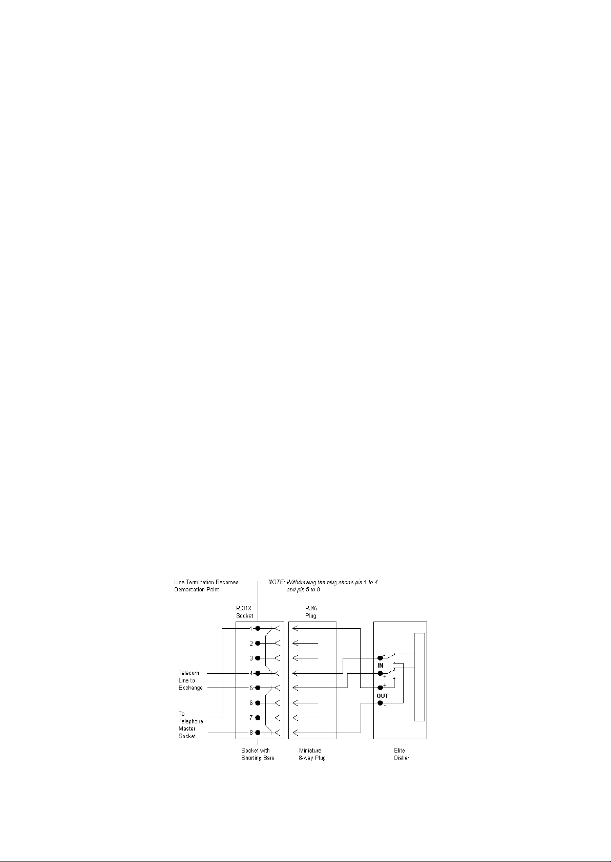
Connection to the Telecom network should be made in accordance with Access Standards Newsletter #65 dated
November 1993. This connection is to be readily accessible to allow disconnection in the event of a fault. An
example of this connection method is shown below.
NOTE: The telephone line must not enter the cabinet through the same cable entry hole as any 230
volt mains cables. A separate cable entry must be used for 230 volt cabling
When using one of the knock-outs around the side of the cabinet for supply entry, a suitable bushing must be
used where the supply cables pass through a knock-out.
The transmit level from this device is set at a fixed level and because of this there may be circumstances where
this device does not give its optimum performance. Before reporting such occurrences as faults, please check the
line with a standard Telepermitted telephone, and do not report a fault unless the telephone performance is
impaired.
This automatic dialing equipment shall not be set up to make calls to the
Telecom "111" Emergency Service
Page 6
Page 7
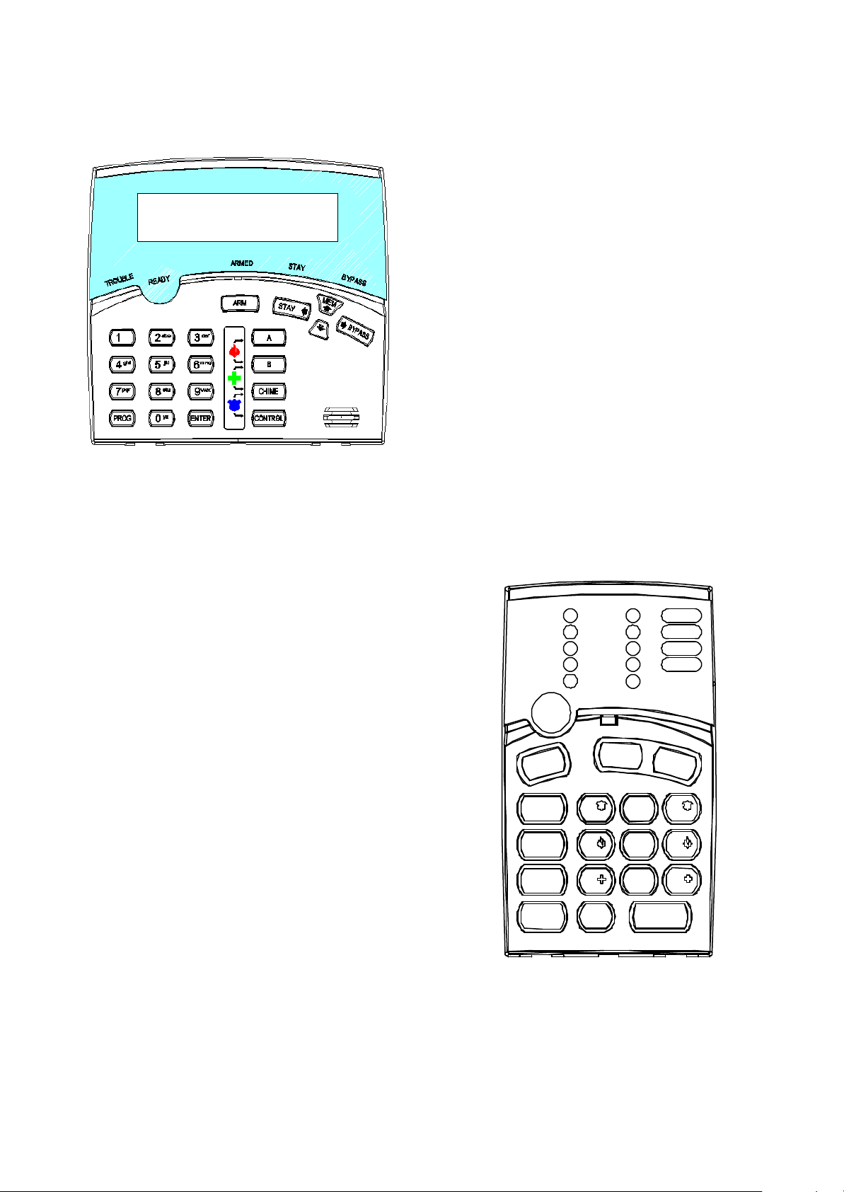
PW-8 KEYPAD OPTIONS
LCD-KEYPAD
ü Multiple language versions
ü LED indicators … READY , ARMED, TROUBLE….
ü 3 KeyPad activated alarms …. FIER,MEDICAL,
PANIC
ü Audible feedback of correct key entries, pre-alert ,
ü system trouble
ü Backlit keypad and display with boost control
ü keypad tone control
ü Large 32-character LCD display
- system menus and prompts
- trouble in dications
- time &date clock
- viewable event buffer
- all system parameters programming
- customizable zone labeling
LED-KEYPAD
ü LED indicators … READY , ARMED, TROUBLE….
ü 4 KeyPad activated alarms …. FIER,MEDICAL,
PANIC
ü Audible feedback of correct key entries, pre-alert ,
ü system trouble
ü Backlit keypad
ü Viewable event buffer
ü All system parameters programmable
1
2
3
4
A
Ready-Byp
5
System
6
Trouble
7
Program
8
B
Page 7
CONTROL
ARM
STAY
BYPASS
PROGRAM
MEMORY
1
4
2
5 6
7
0 ENTER
PANIC
3
98
Page 8
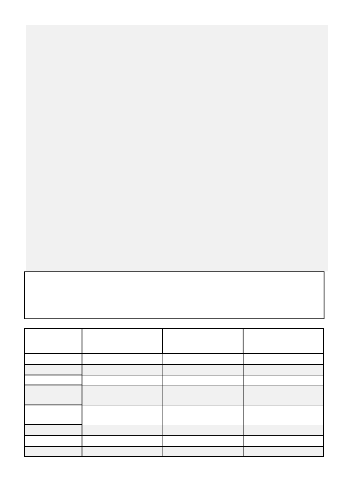
KEYPAD LED or LCD INSTALLATION
INSTALLATION
Remove the Well Mount Bracket (Back cover) by unscrewing the holding screw at the bottom side.
Screw the bracket to the wall using the mounting holes provided with the necessary number of screws.
Make sure the base is mounted right side up.
When fixing the bracket to the wall make sure the top of the screw heads will not touch or short out the underside
of the PCB when the top half of the keypad is reinstalled.
Insert the wire through the wire access hole at centre of the base.
Connect the 4 or 5 wires to the 5 way terminal block on the back side of the keypad PCB, make sure to match the
cables up with the terminals as marked on the control panel's keypad port.
The 5th wire is connected from the "LINE" terminal of the keypad to the "Lin” (Listen) terminal of the PW8 PCB
keypad port.
Once the cables have been terminated and the required address allocated (see section below) replace the front
half of the keypad onto the bracket by first engaging the clips at the top edge and then close the front down and
screw it in at the bottom. Now stick the zone list provided to the inside of the keypad cover.
WIRING
The PW8 keypad connects to the PW 8 Controller via a 4 or 5 wire data security cable. A maximum of 8 LED
keypads can be connected, each wired in parallel. A 5th wire may be used to provide a "Listen -in" facility at the
keypad when an PW8 communicator panel is being used.
The maximum recommended cable using standard 0.2mm security cable is 50m. Cable runs exceeding this
distance may require 0.5mm cable. Always use good quality cable. Some installations may require CAT5 data
cable to ensure dat a integrity in noisy sites.
User information :
Keypad LCD — Power Wave CR16M-LCD Keypad
Users’ Operating and Programming Guide
Keypad LED — Power Wave – 8
Users’ Operating and Programming Guide
When the PW-4 is displaying codes and address values in program mode it may be necessary to display the
9 and 0 digits. As there are no Zone indicators for 0 and 9 the "A" and "B" indicators are used.
i.e.. When displaying values in program mode
LIGHT\INDICATION
READY\BYP Zone Unsealed All Zones Sealed A Zone is bypassed
SYSTEM
TROUBLE Normal Trouble Alarm Active New Trouble Alarm
PROGRAM
OFF
Normal System Alarm Reset New System Alarm
Run Mode Client Program Mode Installer Program Mode or
ON STEADY
FLASHING
Control Function Active
READY\BYP
& PROGRAM
ZONES 1-4
Armed A
Armed B
- Bypass Mode Active
(Zones can be Bypassed)
Zone Secure Zone Violated Zone in Alarm
Partition A Disarmed Partition A Armed Partition A STAY Mode
Partition B Disarmed Partition B Armed Partition B STAY Mode
Page 8
-
Page 9
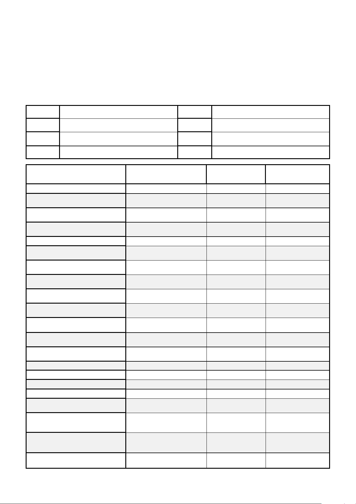
VIEW MEMORY MODE
When viewing the memory event buffer at the keypad by pressing the “MEMORY” button, the first thing that will
always be display ed is the “SYSTEM” LED. If the system led turns on but no other Zone LED’s are on at the same
time, this means that there are no current system alarms. If a zone LED or LED’s are On then this indicates system alarms that have not yet cleared. The zone LED’s 1-8 are pre-defined as to what system alarm they will display. These system alarm indications are shown in the table below. Following the display of current system alarms
the panel will then sequence through the 127 historical memory events starting at the most recent event. The second table shows the alarm events that can be displayed in memory mode and what indicators are used to show
them.
LED # 1
Battery Low
LED # 5
Radio Pendant Battery Low
LED # 2 Mains Failure LED # 6 Supervised Detector Failure
LED # 3
Telephone Line Failure
LED # 7
Zone Inactivity Timeout
LED # 4 Radio Detector Battery Low LED # 8 Dialer Kiss-off Failure
EVENT TYPE \ INDICATION
DEVICE INDICATOR STATUS
?
ACTIVATION Zones 1-4 LED's 1-4 On Steady
BYPASS Zones 1-4 READY/BYPL
DETECTOR TAMPER
(SHORT CIRCUIT)
DETECTOR TAMPER
(OPEN CIRCUIT)
CABINET TAMPER
LOW BATTERY Controller Battery SYSTEM
MAINS FAILURE Controller Mains Supply SYSTEM
RADIO ZONE LOW BATTERY Radio PIR
PENDANT LOW BATTERY
PANIC BUTTON (or BUTTONS
1&3 PRESSED TOGETHER)
FIRE ALARM (BUTTONS 4&6 PRESSED
TOGETHER)
MEDICAL ALARM (BUTTONS 7&9
PRESSED TOGETHER)
PENDANT PANIC
ARMED A
ARMED B
STAY MODE A Area A STAY Mode ON AREA A Flashing
STAY MODE B
DURESS ALARM
SUPERVISED RADIO ALARM
ZONE INACTIVITY ALARM Zones 1-4 READY/EXCL
TELEPHONE LINE FAILURE
Zones 1-4 TROUBLE
Zones 5-8 TROUBLE
Cabinet or Satellite Siren TROUBLE Flashing
Zone 1-4
Radio Key
User 1-4
Keypad Panic SYSTEM Flashing
Keypad Fire SYSTEM
Keypad Medical SYSTEM
Radio Key
User 1-4
Area A is Armed AREA A On Steady
Area B is Armed AREA B On Steady
Area B STAY Mode ON AREA B Flashing
Duress Alarm TROUBLE
Supervised Radio
Passive Infra-Red
Phone Line Failure TROUBLE
LED's 1-4
LED's 1-4
LED's 5-8
LED 1
LED 2
LED's 1-4 Flashing
TROUBLE
LED's 1-4
AREA A
AREA B
SYSTEM
LED 1-4
AREA A & B
SYSTEM
TROUBLE
LED’s 1-4
TROUBLE
LED’s 1-4
LED 3
On Steady
On Steady
Flashing
On Steady
Flashing
On Steady
On Steady
On Steady
On Steady
On Steady
On Steady
Flashing
Flashing
Flashing
Flashing
Flashing
Flashing
Flashing
On Steady
Flashing
On Steady
Flashing
Flashing
On Steady
On Steady
On Steady
On Steady
On Steady
Page 9
Page 10
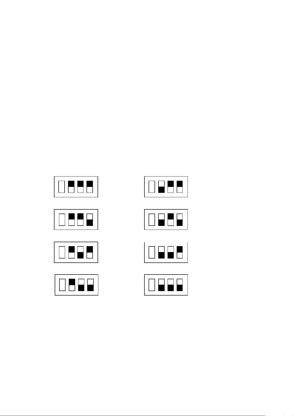
LED KEYPAD ADDRESS ASSIGNMENT
Each of the 8 possible LED keypads which are able to be connected to your PW8 panel must be addressed
individually to avoid BUS conflicts when multiple users are operating different keypads simultaneously. As
default, each key pad comes addressed as #1 (Switches A B and C at ON position).
To assign a keypad as address #2, change switch A to OFF position.
To assign a keypad as address #3, change switch B to OFF position.
To assign a keypad as address # 4, change switches A and B to OFF position.
INDIVIDUAL KEYPAD ADDRESS SETTING
D C B A
D C B A
D C B A
D C B A
KEYPAD
# 1
KEYPAD
# 2
KEYPAD
# 3
KEYPAD
# 4
D C B A
KEYPAD
# 5
D C B A
KEYPAD
# 6
D C B A
KEYPAD
# 7
D C B A
KEYPAD
# 8
Page 10
Page 11
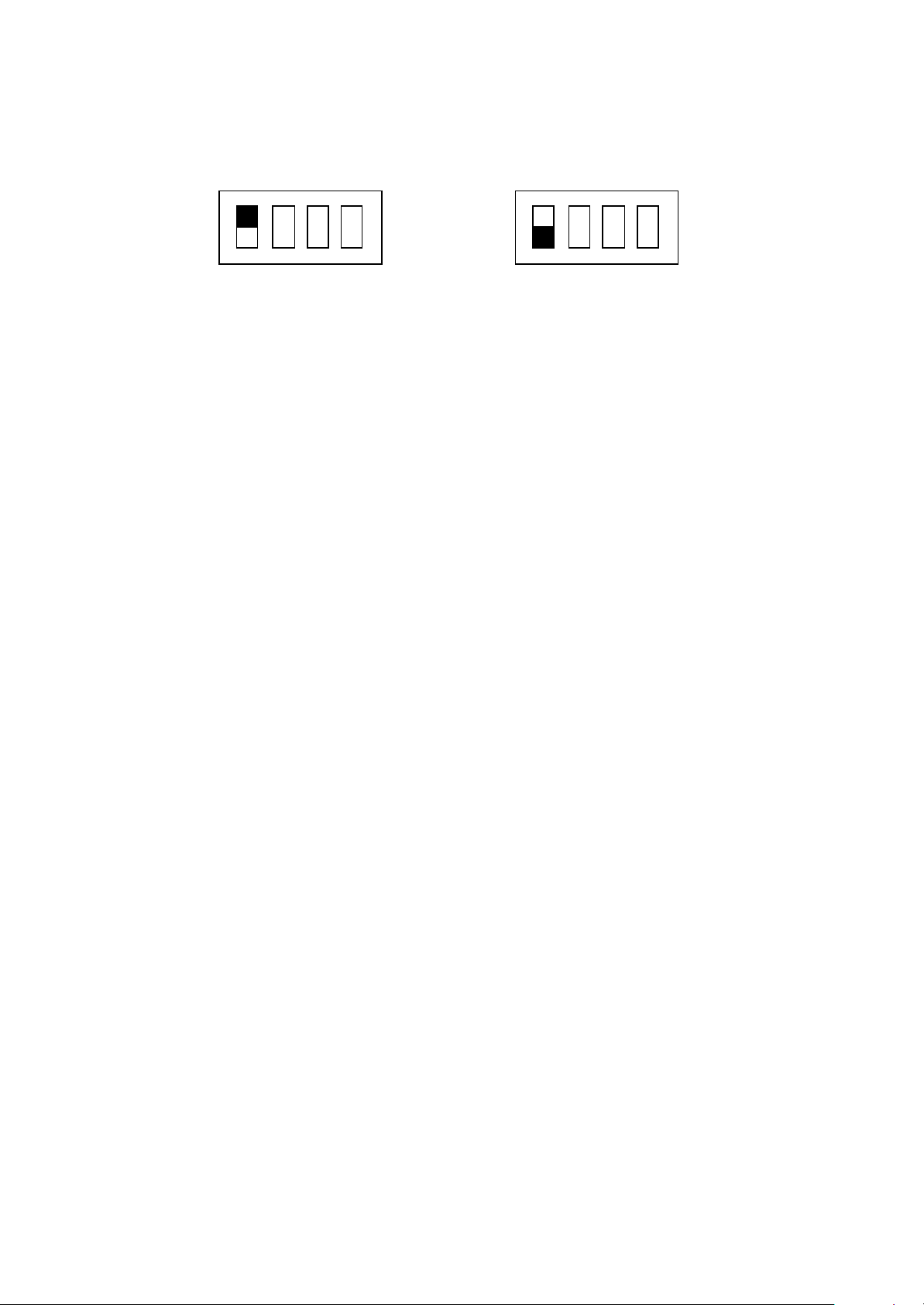
KEYPAD TAMPER OPTION SETTING
Switch marked D used to Enable and Disable the Keypad Tamper option:
D C B A D C B A
TAMPER DISABLE
TAMPER ENABLE
LED KEYPAD FUNCTIONS
The PW-8 LED Keypad consists of; an 18 button, backlit silicone rubber keypad, 14 LED ICON indicators and an
internal piezo buzzer housed in a modern white plastic housing. The plastic housing has a hinged front lid to
cover and protect the rubber buttons when not in use. All the electronics are contained on a single circuit board
inside the housing.
BUTTONS
The 18 silicone rubber buttons are used for the following functions.
In normal operating mode the numeric keys are used for entering Access Codes. In Program Mode the numeric
keys are used for entering options & new values.
The buttons with text labels are used as function buttons and select the options indicated by the text and
normally precede other button presses, e.g. to enter Bypass Mode press <BYPASS> and the numeric key
corresponding to the zone number you wish to be bypassed.
The PROGRAM Key is used to prefix opt ion selections in the program modes e.g.<PROGRAM> 4 <ENTER>
selects User Code 4. The PROGRAM key is also used prior to a Master Code to enter user program mode from
normal operating mode.
The ENTER Key is used to enter access or program codes. It is normally used at the end of a button
sequence.
The CONTROL button, if enabled, is used to isolate day zone audible alarms if temporarily not required and/or
to directly control outputs if programmed.
ICON LED INDICATORS
The ICON LED indicators are used to display system conditions including Zone status, Battery state, Tamper
etc. Please refer to the LED table on page 7 for a full explanation of the conditional displays.
INSTALLING FW-RCV/RX-40 RADIO RECEIVERS
The PW8 is fully high level compatible with the new FW-RCV/RX-40 radio receivers. The addition of this
receiver will add wireless capability to your system in the form or wireless PIR detectors, Wireless Radiokey
transmitters and wireless reed switch transmitters. The RX receiver connects to the same communications port
as the keypads and can be installed , either inside the cabinet, or if preferred, may be installed at a remote
location. The RCEIVERS are available in 3 frequencies, 915MHz ,433 MHz or 868 MHz.
The RX receivers requires 4 cores and can successfully be run in 0.2mm unscreened cable over a distance of
up to 100metres. The RX has 12v connections labeled POS and NEG which are wired to the 12v supply and
CLK and DATA terminals for connection to the communications bus.
The green LED fitted to the RX receivers will indicate when the unit is in "Learn" mode (Flashing - see P601E)
or when it is receiving an actual radio transmission (On Steady)
Page 11
Page 12

PROGRAMMING YOUR PW-8
HOW TO PROGRAM
The programming sequence always follows this pattern:
<PROGRAM> - <1,2 or 3 digit addres s> - <ENTER>
3 short beeps if OK - 1 long beep if error
The LEDs will display current value or status
Enter the new value or opt ion <New Value> - <ENTER>
3 short beeps if OK - 1 long beep if error
Throughout this manual you will see program instructions ex pressed as
P 10 E 5 E as an example.
***In this example the <P> represents the PROGRAM key and <E> represents the ENTER key.
ACCESS TO PROGRAMMING ON POWER UP (INSTALLER MODE)
When power is applied to the controller for the first time, with the panel tamper input open, the panel will inhibit
tamper alarms and ready the panel to enter INSTALLER PROGRAM Mode (unless the Installer Lock-out option
P170E2E has previously been enabled). At this point you can go to any keypad which is connected to the panel
and press “PROGRAM” “ENTER” which will automatically put that keypad into full Program mode, Program LED
Flashing. (NOTE: Only one keypad can be in Program mode at any time)
ACCESS TO INSTALLER PROGRAM MODE FROM RUN MODE
Before you can enter Installer program mode, the panel must not be Armed or in STAY mode
Press <PROGRAM> - <Code 11 ( Installer Code)> - <ENTER>
Program light will Flash
Note: Default Installer Code (Code 11) is 000000.
You are now in Installer Program Mode. Any program addresses may be viewed or changed in this mode.
Note: Using LCD KP - Where there are multiple options at one address , Press <CONTROL>+<BYPASS>
to prompt the options description. Press <MEM> to display all options at one address .
To switch back to address mode press <CONTROL>+<BYPASS> again .
ACCESS TO CLIENT PROGRAM MODE FROM RUN MODE
Press <PROGRAM> - <User Code> - <ENTER>
Program light On Steady
Note: Default User Code (P1) is 123.
You are now in Client Program Mode. Only User Codes 1-10 can be viewed or changed in this mode. Codes
may be denied access to Client mode, allowed access to change their code only or allowed access to view &
change all user codes.
RESETTING BACK TO FACTORY DEFAULT SETTINGS (From Install Mode Only)
This address allows you to reset the panel back to the factory defaults (Reset All defaults).
e.g. To reset All System defaults including User Codes (P62 0 E)
Press <PROGRAM> - 620 - < ENTER>
3 beeps - Program light flashing
After the system configuration has been reset back to defaults, all values, options & Codes will be set to the
values shown in the Program Option Summary as defaults. These value & opt ion selections have been chosen
as the most common set -up for the majority of systems.
P621-P625 allow selective defaults to be set ( refer to program summary at the back of the manual for more
details).
Page 12
Page 13
TO EXIT PROGRAM MODES
To exit either program mode when you have finished programming:
Press <PROGRAM> - < ENTER>
Program light goes out
The panel is now back in Run Mode, any program changes you have made will have replaced previous values
and be in effect.
Note: During programming Tampers and 24 hour alarms are disabled which allows quiet access to the panel,
detectors and satellite siren units etc. On exiting program mode, all inputs are scanned and if any tampers or 24
Hr alarms are present an activat ion will occur.
PROGRAMMING USER CODES
Note: Where there are multiple options at one address, options 0 & 9 have been reserved. Entering a 0
at the address will turn all options off whereas entering a 9 will turn all options on.
USER CODES - (P1E to P10E) & (P11E)
There are 11 codes available in the PW-8, 10 user codes and 1 install code. The user codes are located in
addresses 1-10. As default, Code 1 has Master Code permissions and must be used to enter Client program
mode. The Installer code is stored at address 11 and is used to access Installer Program mode.
Codes 1-10 may be varied in length from 1 to 6 digits. Code 11 must be 3-6 digits.
To program a User Code you must first be in client or installer program mode, then select the address from 1-10.
(If there is already a code programmed at this address, it will be flashed back to you) Now enter the code then
press the ENTER key.
e.g.. P 1 E 1234 E
3 beeps - program light on solid or flashing
In this example we have set Code 1 ( Master Code ) to be 1234.
e.g.. P 5 E 567 E
3 beeps - program light on solid or flashing
In this example we have set code 5 to be 567
To replace a code simply enter the new code in the same address as the old code. This will overwrite the
previous code but maintain the user permissions as mapped to that user number.
To clear or delete a code simply enter the Bypass button at the address where the old code is stored.
e.g.. P 3 E <BYPASS> E
3 beeps - Program light on solid or flashing
User Code # 3 Erased
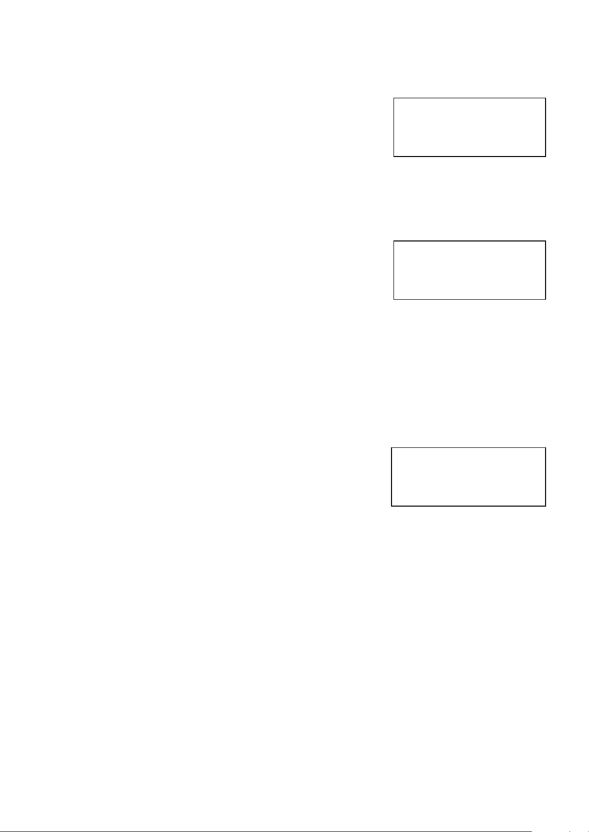
When flashing back codes and values Zone indicators 1-8 are used to indicate digits 1-8. The digit 0 is indicated
by the "A" light and 9 is indicated by the "B" light.
User 5 Code
567
Page 13
Page 14
USER CODE OPTIONS
USER CODE PERMISSIONS (Code Options) - P21E-P30E
Option 1 - Code has Area A permissions
Option 2 - Code has Area B permissions
Option 3 - Code can Arm Area
Option 4 - Code can Disarm Area
Option 5 - Code can turn STAY on
Option 6 - Code can turn STAY off
Option 7 - Code can Program their own code
Option 8 - Code can Program Other Codes
NOTE: Options 3,4, 5 & 6 are used in conjunction with options 1 & 2 whereby options 3,4,5 & 6 determine
the functions and options 1 & 2 determine the area of operation. If option 8 is on for the user, that user can
change the telephone numbers and change the Real Time Clock.
INSTALLER CODE - P11E
This code is used to enter full Installer Program mode (Program LED flashing).
The default installer code is 000000. To change this code enter your new
installer code at the P11E address. The new code will be flashed back to you
automatically. The Program code may vary from 3-6 digits in length.
User 1 Options
1 2 3 4 5 6 7 8
Installer Code
000000
PROGRAMMING OUTPUT OPTIONS
NOTE: With all output programming option s we refer to outputs 1-8.
Only outputs 1-2 are available as standard, with outputs 3-8 requiring
the connection of the optional 4 way output expander unit that
connects to the keypad buss ( the output expander provides 4
change-over relay contacts).
OUTPUT OPTIONS A- P31E-P38E
This block of addresses (P31E - P38E) are used to map output
modifiers to each of the 8 outputs ava ilable on the PW-8.
P31E 1E Invert output - Default off (P34E =on)
2E Flash output - Default off
3E Single pulse to output - Default off
4E Lockout output once reset - Default off
5E Siren Driver to output - Default off
6E “Control” button & DTMF Remote Control can operate output - Default off
7E Output flashes on a 24 hour zone alarm - Default off
8E Day zones (CHIME) linked to pulse timer - Default off
Option 1 Invert Output - This option is used to invert the normal state of the output. The PW-8 uses open
collector type transistor switches and the default state of all outputs is off or high. When in alarm the
transistor switch is turned on and the output is switched low. The invert option reverses this function.
Option 2 Flash Output - This option causes the output to turn on and off at a rate set by the pulse timer for this
output (P221E-P228E) when in alarm and is normally used to flash a lamp during an activation.
Option 3 Single Pulse to Output - This option, when applied, produces a single pulse at the output during an
alarm (the pulse time is the value programmed at the output pulse timer address, P221E -P228E).
Option 4 Lockout Once Reset - This option is used to limit the output to one operation per arming period.
Option 5 Siren Driver to Output - This option causes the output to be a modulated output designed to drive 8
ohm 10 watt horn speakers directly. Outputs 1 & 2 can have the siren driver feature. A different tone is
generated at output 1 to that at outputs 2.
NOTE: DO NOT CONNECT A HORN SPEAKER TO OUTPUT 1 or 2 WITHOUT FIRST TURNING
Options A O/P 1
- - - - - - - -
Page 14
Page 15

THIS OPTION ON OTHERWISE DAMAGE MAY OCCUR TO THE OUTPUT CONCERNED.
Option 6 “Control” button & DTMF Remote Control can operate output - The “Control’ button on the
PW-8 keypad can be used to turn outputs on or off. Also, if the optional 90 second voice board is
fitted, the outputs can be turned On or Off remotely via a Touchtone (DTMF) phone. For this to
happen this option must be turned on for the output/s concerned. To turn an output on locally at the
keypad the operator simply presses the “Control’ button at which time the “System” & “Program”
LED’s will illuminate to indicate that the Control mode is active. If any controllable outputs are
currently on, the relevant green led (LEDS 1-8) will be on. The operator can now press a button
relating to the output/s they wish to control e.g. pressing the “1” button will turn output 1 on or off,
The “2” button for output 2 etc. When an output state is changed the LED will indicate the change of
state. When finished the operator then presses the “Enter” button to cancel the Control mode and
return to normal. To operate the output/s via a telephone please refer to the instructions supplied
with the voice board.
Option 7 Flash 24 hour alarm - If a 24 hour zone activates the alarm this option will cause the output to
flash at a rate equal to the value set for the pulse timer (P221E -P228E).
Option 8 Day Zones (CHIME) Linked to Pulse Timer - Day Zones programmed to this output will pulse at
the pulse timer rate (P221E-P228E) for the duration of the day zone to output timer (P211E-P218E)
P32E - P38E As per P31E above for Outputs 2-8
PROGRAMMING OUTPUT OPTIONS cont.
OUTPUT OPTIONS B - P41E - P48E
In this block of addresses P41E relates to output #1, P42E relates to output #2 etc
P41E 1E Pendant Panic to Output - Default on (P43E-48E = OFF)
2E Keypad Panic to Output - Default on (P43E-48E = OFF)
3E Keypad Fire to Output - Default off
4E Keypad Medical to Output - Default off
5E Cabinet Tamper to Output- Defaulton (P43E-48E = OFF)
6E Duress Alarm to Output - Default off
7E Mains Fail to Output - Default off
8E Battery Low to Output - Default off
Option 1 Pendant Panic to Output - This option is used to map the operation of the Radio Pendant panic
button to an output i.e. when the Radio Panic button is pressed any output with this option enabled
will turn on.
Option 2 Keypad Panic to Output - This option is used to map the Keypad Panic Button, or the 2 button
Panic function to an output. Keypad Panics are generated when a user presses the Panic Button or
buttons 1 & 3 Simultaneously at the keypad.
Option 3 Keypad Fire to Output - This option is used to map the manual Keypad Fir e alarm function to an
output. The keypad Fire alarm is generated when a user presses buttons 4 & 6 Simultaneously at
the keypad.
Option 4 Keypad Medical to Output - This option is used to map the manual Keypad Medical alarm
function to an output. The keypad Medical alarm is generated when a user presses buttons 7 & 9
Simultaneously at the keypad.
Option 5 Cabinet Tamper to Output - This option is used to map activations of the common Tamper Input
to an output. This common tamper input is normally used to STAY the panel cabinet and satellite
tamper switches.
Options B O/P 1
1 2 - - 5 - - -
Page 15
Page 16

Option 6 Duress Alarm to Output - This option will map the Duress Function to an output. Programming of
the Duress Digit is at address P230E.
Option 7 Mails Fail To Output - A mains failure will be indicated at this output when option 7 is enabled at
this address. The Alarm Reset Timer must be set to “0” when this option is used.
Option 8 Low Battery - A battery Low condition will be indicated at this output when option 8 is enabled at
this address. The alarm reset timer must be set to “0” when this option is used.
P42E - P48E As per P41E above for Outputs 2-8
MAPPING ZONE ALARMS TO OUTPUTS
ZONE ALARM MAPPING TO OUTPUTS - P51E - P58E
When a zone is in alarm (during the ARMED state only) this block of addresses allows individual
zones to be mapped to selected outputs. The default setting is that zones 1-8 will turn on all outputs
1-8 when in alarm.
P51E Zone Alarms to Output #1. Options=Zones 1-8 (Default=1-8)
P52E Zone Alarms to Output #2. Options=Zones 1-8 (Default=1-8)
P53E Zone Alarms to Output #3. Options=Zones 1-8 (Default= 0 )
P54E Zone Alarms to Output #4. Options=Zones 1-8 (Default= 0 )
P55E Zone Alarms to Output #5. Options=Zones 1-8 (Default= 0 )
P56E Zone Alarms to Output #6. Options=Zones 1-8 (Default= 0 )
P57E Zone Alarms to Output #7. Options=Zones 1-8 (Default= 0 )
P58E Zone Alarms to Output #8. Options=Zones 1-8 (Default= 0 )
Alarm To O/P 1
1 2 3 4 5 6 7 8
MAPPING STAY ZONE ALARMS TO OUTPUTS
STAY ZONE ALARM MAPPING TO OUTPUTS - P61E - P68E
When a Stay Mode zone is in alarm (during the STAY
state only) this block of addresses allows individual zones
to be mapped to selected outputs. The default setting
is that zones 1-8 will turn on output 2 only when a STAY
mode alarm occurs.
P61E Stay Mode Zone Alarms to Output #1. Options=Zones 1-8 (Default=1-8)
P62E Stay Mode Zone Alarms to Output #2. Options=Zones 1-8 (Default=1-8)
P63E Stay Mode Zone Alarms to Output #3. Options=Zones 1-8 (Default=None)
P64E Stay Mode Zone Alarms to Output #4. Options=Zones 1-8 (Default=None)
P65E Stay Mode Zone Alarms to Output #5. Options=Zones 1-8 (Default=None)
P66E Stay Mode Zone Alarms to Output #6. Options=Zones 1-8 (Default=None)
P67E Stay Mode Zone Alarms to Output #7. Options=Zones 1-8 (Default=None)
P68E Stay Mode Zone Alarms to Output #8. Options=Zones 1-8 (Default=None)
Stay Alarm O/P 1
1 2 3 4 5 6 7 8
MAPPING 24 HOUR ZONE ALARMS TO OUTPUT
24 HOUR ZONE ALARM MAPPING TO OUTPUTS - P71E - P78E
When a 24 Hour zone is in alarm this block of addresses allows
individual zones to be mapped to selected outputs. The default
setting is that zones 1-8 will turn on output 2 only when a 24 Hour
alarm occurs.
P71E 24 Hour Zone Alarms to Output #1. Options=Zones 1-8 (Default=1-8)
P72E 24 Hour Zone Alarms to Output #2. Options=Zones 1-8 (Default=1-8)
P73E 24 Hour Zone Alarms to Output #3. Options=Zones 1-8 (Default=None)
P74E 24 Hour Zone Alarms to Output #4. Options=Zones 1-8 (Default=None)
P75E 24 Hour Zone Alarms to Output #5. Options=Zones 1-8 (Default=None)
P76E 24 Hour Zone Alarms to Output #6. Options=Zones 1-8 (Default=None)
24 Alarm O/P 1
1 2 3 4 5 6 7 8
Page 16
Page 17

P77E 24 Hour Zone Alarms to Output #7. Options=Zones 1-8 (Default=None)
P78E 24 Hour Zone Alarms to Output #8. Options=Zones 1-8 (Default=None)
MAPPING DAY ZONES TO OUTPUTS
DAY ZONES TO OUTPUTS - P81E - P88E
When a Day zone is unsealed this block of addresses allows
individual zones to be mapped to selected outputs.
The default setting is that no Day zones are mapped to any of
the 8 outputs.
P81E Day Zones to Output #1. Options=Zones 1-8 (Default=None)
P82E Day Zones to Output #2. Options=Zones 1-8 (Default=None)
P83E Day Zones to Output #3. Options=Zones 1-8 (Default=None)
P84E Day Zones to Output #4. Options=Zones 1-8 (Default=None)
P85E Day Zones to Output #5. Options=Zones 1-8 (Default=None)
P86E Day Zones to Output #6. Options=Zones 1-8 (Default=None)
P87E Day Zones to Output #7. Options=Zones 1-8 (Default=None)
P88E Day Zones to Output #8. Options=Zones 1-8 (D efault=None)
Chime To O/P 1
- - - - - - - -
MAPPING ZONE TAMPERS TO OUTPUTS
ZONE TAMPER MAPPING TO OUTPUTS - P91E - P98E
When a zone input is set for Dual-End-of-Line (P130E)
the short & open circuit tampers are automatically enabled
for that zone input. This option allows the zone tamper
alarms to be mapped through to individual outputs. Led 1-4
is a short on the Zone 1-4 and a Led 5-8 is an open
loop in Zone 5-8.
P91E Zone Tamper to Output #1. Options= Zone Tampers 1-8 (Default=1-8)
P92E Zone Tamper to Output #2. Options= Zone Tampers 1-8 (Default=1-8)
P93E Zone Tamper to Output #3. Options= Zone Tampers 1-8 (Default=None)
P94E Zone Tamper to Output #4. Options= Zone Tampers 1-8 (Default=None)
P95E Zone Tamper to Output #5. Options= Zone Tampers 1-8 (Default=None)
P96E Zone Tamper to Output #6. Options= Zone Tampers 1-8 (Default=None)
P97E Zone Tamper to Output #7. Options= Zone Tampers 1-8 (D efault=None)
P98E Zone Tamper to Output #8. Options= Zone Tampers 1-8 (Default=None)
Tamper To O/P 1
1 2 3 4 5 6 7 8
MAPPING RADIO KEYS TO OUTPUTS
RADIO KEY(PENDANT) MAPPING TO OUTPUTS - P101E - P108E
When a Radio Key is to be used to operate a garage door
or similar function this block of addresses allows individual
Radio Keys to be mapped to selected outputs.
The default setting is that none of the 8 Ra dio Keys are
mapped to any outputs.
P101E Radio Key to Output #1. Options=Pendant 1-8 (Default=None)
P102E Radio Key to Output #2. Options=Pendant 1-8 (Default=None)
P103E Radio Key to Output #3. Options=Pendant 1-8 (Default=None)
P104E Radio Key to Output #4. Options=Pendant 1-8 (Default=None)
P105E Radio Key to Output #5. Options=Pendant 1-8 (Default=None)
P106E Radio Key to Output #6. Options=Pendant 1-8 (Default=None)
P107E Radio Key to Output #7. Options=Pendant 1-8 (Default=None)
P108E Radio Key to Output #8. Options=Pendant 1-8 (Default=None)
Page 17
Radio Key O/P 1
- - - - - - - -
Page 18

TEMPORARY OUTPUT DISABLE
This address P109E allows a technician to select any output/s to be temporarily disabled for one alarm or armed
cycle, eg by turning on LEDS 1-4 at P109E then leaving program mode, outputs 1-4 will not turn on following any
alarms. The technician is now free to arm the system to test all monitoring signals without having all of the internal
& external ala rms activating. When the alarm is reset or disarmed all outputs will now work normally again.
P109E Select output # 1-8
Temp O/P Disable
- - - - - - - -
PARTITION “A” OPTIONS
PARTITION “A” OPTIONS - P110E
This address allows modification of how Partition “A” arming, STAY and control keys work at the keypad.
P110E 1E “ARM” button required before code to set- Default off
2E “STAY” button required before code to turn on Stay Mode- Default off
3E “CODE” required to arm- Default off
4E “ARM” button can disarm system during exit delay- Default on
5E “STAY” button can disarm Stay Mode at any time- Default off
6E No Exit Beeps to keypads in Stay Mode- Default on
7E Key-switch Enabled- Default on
8E Key-switch Mode- Default off
Option 1 “ARM” button required before code to set - This option determines if the “ARM” button must be
pressed before a code is entered to set Area “A”. If a keypad is assigned to both Partitions, this
option should be set to allow individual arming of each area. This option disables the Arm button from
disarming during the exit delay.
Option 2 “STAY” button required before code to set - This option determines if the “STAY” button must be
pressed before a code is entered to set Area “A” Stay Mode. If a keypad is assigned to both
Partitions, this option should be set to allow individual arming of Stay Mode for each area.
Option 3 “CODE” required to set - If this option is set, the “ARM” button is disabled and the panel requires a
code to arm as well as disarm.
Option 4 “ARM” button can disarm during exit delay - If this option is on then the “arm” button can disarm
Partition “A” during the exit delay time with a single press of the button. If the option is off then the
alarm can only be unset by a valid code, even during the exit delay time.
Option 5 “STAY” button can disarm Stay Mode - This option allows the “Stay” button to disarm STAY mode
at any time (including when Stay Mode is fully set). If the option is off then Stay Mode can only be
unset by a valid code. This feature is defaulted to keypad addresses 1 & 4 ( 4 being the default
address for the STAY key station).
Option 6 No Exit Beeps to keypads in Stay Mode - This option stops the exit beeps from occurring at all
keypads when Stay Mode is set. Normally used for silent night arming.
Option 7 Enable Partition “A” Key-switch - If this option is turned on then the system tamper input (Tmp)
becomes a Dual End of Line Input (Refer to Type 4 drawing on Page 4 for wiring details). The low
input 4K7 is reserved for Partition “A” key-switch operation. An open circuit will still be seen as a
system tamper.
Option 8 Key-switch Mode - If this option is On then the key -switch has a toggle function (ie the arm/disarm
state will follow the key -switch state). If Off then the key-switch is momentary (ie each single pulse
will change the arm/disarm state). The panel tamper input is used to provide the key -switch function.
Page 18
Page 19

Area A Option
- - - 4 6 7 - -
PARTITION “A” OUTPUT OPTIONS
PARTITION “A” OUTPUT OPTIONS - P111E - P118E
This block of addresses sets a number of output options which are
specific and unique to the operation of partition or Area "A".
Activity in Areas "B" will have no direct eff ect on the options set
at these addresses.
P111E 1E Arm status to output- Default off (P113E=ON)
2E Stay Mode on status to output- Default off (P113E=ON)
3E Disarm status to output- Default off
4E Pendant chirps for Arm to output - Default off
5E Pendant chirps for Stay Mode On to output - Default off
6E Pendant chirps for Disarm to output - Default off
7E Pulse on Arming to output - Default off (P114E=ON)
8E Pulse on Disarming to output - Default off
Option 1 Arm indication to output - This opt ion will turn the output on when Area "A" is armed. The output
will turn on at the start of the exit delay and turn off when the Area is disarmed. The output reset time
should be set to zero.
Option 2 Stay Mode On indication to output - This option will turn the output on when Area "A" Stay Mode is
armed. The output will turn on at the start of the exit delay and turn off when Stay Mode is disarmed.
The output reset time should be set to zero.
Option 3 Disarm indication to output - This option will turn the output on when Area "A" is Disarmed. The
output will turn on when the Area “A” is disarmed and turn off when the Area is Armed or in Stay
Mode. The output reset time should be set to zero.
Option 4 Pendant Chirps for Arm to output - This option will map two short pulses (Chirps) to the output
when Area "A" is armed via a radio key (Pendant) ,( the length of the pulses is set by the pulse timer
P221E-P228E).
Option 5 Pendant Chirps for Stay Mode On to output - This option will map two short pulses (Chirps) to the
output when Area "A" Stay Mode is set via a radio key (Pendant) ,( the length of the pulses is set by
the pulse timer P221E-P228E).
Option 6 Pendant Chirps for Disarm to output - This option will map four short pulses (Chirps) to the output
when Area "A" is Disarmed via a radio key (Pendant) ,( the length of the pulses is set by the pulse
timer P221E -P228E).
Option 7 Pulse on Arming to output - This option will map a pulse to the Output each time Area"A" is armed
( the length of the pulses is set by the pulse timer P221E -P228E).
Option 8 Pulse on Disarming to output - This option will map a pulse to the Output each time Area"A" is
disarmed ( the length of the pulses is set by the pulse timer P221E-P228E).
Note: P112E through P118E are as above but applied to outputs 2-8
AreaA Opt O/P 1
- - - - - - - -
Page 19
Page 20

PARTITION “B” OPTIONS
PARTITION “B” OPTIONS - P120E
This address allows modification of how Partition “B” arming, STAY and control keys work at the keypad.
P120E 1E “ARM” button required before code to set- Default off
2E “STAY” button required before code to turn on Stay Mode- Default off
3E “CODE” required to arm- Default off
4E “ARM” button can disarm system during exit delay- Default on
5E “STAY” button can disarm Stay Mode at any time- Default on
6E No Exit Beeps to keypads in Stay Mode- Default off
7E Key-switch Enabled- Default on
8E Key-switch Mode- Default off
Option 1 “ARM” button required before code to set - This option determines if the “ARM” button must be
pressed before a code is entered to set Area “B”. If a keypad is assigned to both Partitions, this
option should be set to allow individual arming of each area. This option disables the Arm button from
disarming during the exit delay.
Option 2 “STAY” button required before code to set - This option determines if the “STAY” but ton must be
pressed before a code is entered to set Area “B” Stay Mode. If a keypad is assigned to both
Partitions, this option should be set to allow individual arming of Stay Mode for each area.
Option 3 “CODE” required to set - If this option is set, the “ARM” button is disabled and the panel requires a
code to arm as well as disarm.
Option 4 “ARM” button can disarm during exit delay - If this option is on then the “arm” button can disarm
Partition “B” during the exit delay time with a single press of the button. If the option is off then the
alarm can only be unset by a valid code, even during the exit delay time.
Option 5 “STAY” button can disarm Stay Mode - This option allows the “Stay” button to disarm STAY mode
at any time (including when Stay Mode is fully set). If the option is off then Stay Mode can only be
unset by a valid code. This feature is defaulted to keypad addresses 1 & 4 ( 4 being the default
address for the STAY key station).
Option 6 No Exit Beeps to keypads in Stay Mode - This opti on stops the exit beeps from occurring at all
keypads when Stay Mode is set. Normally used for silent night arming.
Option 7 Enable Partition “B” Key-switch - If this option is turned on then the system tamper input (Tmp)
becomes a Dual End of Line Input (Refer to Type 4 drawing on Page 4 for wiring details). The high
input 8K2 is reserved for Partition “B” key-switch operation. An open circuit will still be seen as a
system tamper.
Option 8 Key-switch Mode - If this option is On then the key -switch has a toggle function (ie the arm/disarm
state will follow the key -switch state). If Off then the key-switch is momentary (ie each single pulse
will change the arm/disarm state). The panel tamper input is used to provide the key -switch function.
AreaB Option
- - - 4 5 - - -
PARTITION “B” OUTPUT OPTIONS
PARTITION “B” OUTPUT OPTIONS - P121E - P128E
This block of addresses sets a number of output options which are specific and unique to the operation of partition
or Area "B". Activity in Areas "A" will have no direct effect on the options set at these addresses.
P121E 1E Arm status to output- Default off
2E Stay Mode on status to output- Default off
3E Disarm status to output- Default off
Page 20
Page 21

4E Pendant chirps for Arm to output - Default off
5E Pendant chirps for Stay Mode On to output - Default off
6E Pendant chirps for Disarm to output - Default off
7E Pulse on Arming to output - Default off (P124=ON)
8E Pulse on Disarming to output - Default off
Option 1 Arm indication to output - This option will turn the output on when Area "B" is armed. The output
will turn on at the start of the exit delay and turn off when the Area is disarmed. The output reset time
should be set to zero.
Option 2 Stay Mode On indication to output - This option will turn the output on when Area "B" Stay Mode is
armed. The output will turn on at the start of the exit delay and turn off when Stay Mode is disarmed.
The output reset time should be set to zero.
Option 3 Disarm indication to output - This option will turn the output on when Area "B" is Disarmed. The
output will turn on when the Area “B” is disarmed and turn off when the Area is Armed or in Stay
Mode. The output reset time should be set to zero.
Option 4 Pendant Chirps for Arm to output - This option will map two short pulses (Chirps) to the output
when Area "B" is armed via a radio key (Pendant) ,( the length of the pulses is set by the pulse timer
P221E-P228E).
Option 5 Pendant Chirps for Stay Mode On to output - This option will map two short pulses (Chirps) to the
output when Area "B" Stay Mode is set via a radio key (Pendant) ,( the length of the pulses is set by
the pulse timer P221E-P228E).
Option 6 Pendant Chirps for Disarm to output - This option will map four short pulses (Chirps) to the output
when Area "B" is Disarmed via a radio key (Pendant) ,( the length of the pulses is set by the pulse
timer P221E -P228E).
Option 7 Pulse on Arming to output - This option will map a pulse to the Output each time Area "B" is armed
( the length of the pulses is set by the pulse timer P221E -P228E).
Option 8 Pulse on Disarming to output - This option will map a pulse to the Output each time Area "B" is
disarmed ( the length of the pulses is set by the pulse timer P221E-P228E).
Note: P122E through P128E are as above but applied to outputs 2-8
AreaB Opt O/P 1
- - - - - - - -
PROGRAMMING ZONE EOL OPTIONS
SINGLE ZONE EOL OR DUAL ZONE INPUT (4 or 8 zones) - P130E - Default=1-8 OFF
P130E 1-8E Single Zone EOL or dual zone input - This optio n is used to define the PW-8 as a 4 zone
panel with or without EOL (End of Line Resistors) or an 8 zone panel. Options 1-4 relate to
zones 1-4 respectively and decide whether the zone input requires an end of line resistor or
just a short or open circuit to seal the zone. If the LED’s are OFF (Type 1 Drawing on Page 4 )
then a short on the input is all that is needed to seal the input. If the LED’s 1-4 are ON (Type 2
Drawing on Page 4 ) then the input requires a 2k2 resistor to seal the zone. Options 5-8 rel ate
to zone inputs 1-4 respectively and allow “Zone Doubling” to be turned on for a particular input.
When a zone has been assigned "Zone Doubling" the one input is used for both a low (1-4)
and a high (5-8) zone. When zone doubling is turned On, zone 1 input is used for zones 1 & 5,
zone 2 input is used for zones 2 & 6, zones 3 input is used for zones 3 & 7 and zone 4 input is
used for zones 4 & 8. Zone doubling is assigned on a zone -by-zone basis. Each input can be
configured as two zones (Type 3 drawing on page 4 ) without tamper monitoring or two zones
(Type 4 drawing on page 4 ) with tamper monitoring. To use the Type 3 mode for zones 1 & 5
Page 21
Page 22

you must turn LED#1 Off and LED#5 On. To use Type 4 mode for zones 1 & 5 you must turn
LED#1 On and LED#5 On. The same applies to the other zone inputs. Refer to the table on
Page 4 for more details.
EOL & Doubling
- - - - - - - -
PROGRAMMING ZONE OPTIONS
PROGRAMMING ZONE OPTIONS– P129E,P131E-P150E
This block of addresses (P129E - P150E) are used to select the desired functions for Zones 1-8
P131E Partition “A” Zones Zones 1-8. (Default = All 8 zones)
This option allows programming of which zones will be assigned to Partition A. If a zone is in Both A & B then it
becomes common to both Areas.
P132E Partition “B” Zones Zones 1-8. (Default = No zones)
This option allows programming of which zones will be assigned to Partition B. If a zone is in Both A & B then it
becomes common to both Areas.
P133E Zone is NC or NO Zones 1-8. (Default =Led Off, All Zones NC, Normally Closed)
By turning the LED on for zone 1 at this address, the panel is now looking for a Normally Open (NO) contact on
the zone (4K7).
P134E Radio Zone Input Zones 1-8. (Default = No zones)
This option allows programming of which zones will be radio zones. If a zone is a radio zone, the panel ignores
the state of the hardwired input for that zone). If the zone input has been set to tamper monitoring , the tampers
are still active even if zones are set for Radio operation.
P135E Manually BYPASSED Zone Zones 1-8. (Default = All 8 zones)
This option allows programming of which zones can be manually BYPASSED prior to Arming. If a zone has this
option turned off, then that zone cannot be BYPASSED manually). Zones are BYPASSED during the disarm state
and normal zones which are BYPASSED become re-included once the alarm has been set then unset. 24 hour
zones, however remain BYPASSED until manually re-included again. Every time the alarm is set or unset with
zones BYPASSED the keypad will respond with a long beep instead of the normal 3 short beeps to indicate that
excludes are present. When excluding zones, the READY\EXCL & PROGRAM LED’s are on to indicate that you
have entered BYPASS mode. After BYPASSING zones the READY\BYP led will flash when all zones are sealed
to indicate that zones are BYPASSED
P136E Auto-BYPASSED Zone Zones 1-8. (Default = No zones)
This option allows programming of which zones can be automatically BYPASSED at the end of the exit delay if
unsealed at that time. If a zone has this option turned off, then that zone will not auto-BYPASSED and will go into
alarm if not sealed.
P137E Follow/Handover Zone Zones 1-8. (Default = only zone 2 =on )
This option allows programming of which zones will be handover zones. If a zone is a handover zone then it’s
entry delay time will apply provided a non-handover zone is triggered before the handover zone. If no other entry
delays are active when the handover zone is triggered, the zone will activate immediately.
P138E Two Trigger Zone Zones 1-8. (Default = No zones)
This option allows programming of which zones will require two triggers before they activate. To cause an
activation a two trigger zone must alarm twice within the 2 trigger time period, P229E, or 2 two trigger zones can
alarm once each within the two trigger time period before the alarm is generated. If a two trigger zone is unsealed
and remains unsealed for a period longer than the two trigger time period, an alarm will also be generated.
P139E Stay Mode Zone Zones 1-8. (Default = all Zone 1-8)
Page 22
Page 23

This option allows programming of which zones can be assigned as Stay Mode Zones. Only zones programmed
at this address will be active when STAY mode is armed.
P129E 24 Hour Fire Zone Zones 1-8. (Default = No zones)
This option allows a zone to be programmed as a 24 hour fire zone. If programmed as a fire zone, when the
zone causes an alarm if will flash any outputs it is programmed to operate at a rate set by the pulse timer (P221228E).
P140E 24 Hour Zone Zones 1-8. (Default = No zones)
This option allows programming of which zones can be assigned as 24 Hour Zones. Only zones programmed at
this address will be active at all times. If a 24 hour zone has an entry delay assigned to it, the entry delay acts as
an abort timer e.g. the zone must be in alarm longer than the entry delay time before the alarm is activated. If
the zone is sealed before the entry delay expires, no alarm is generated.
P141E Non-Latching 24 Hour Zone Zones 1-8. (Default = No zones)
This option allows programming of which zones can be assigned as Non-Latching 24 Hour Zones. A NonLatching 24 Hour Zone will operate as a normal 24 Hour zone except that when the zone re -seals the zone LED
and any assigned outputs will reset automatically.
P142E Lockout Zone Zones 1-8. (Default = No zones)
This option allows programming of which zones can be assigned as Lockout Zones. A Lockout Zone will only
cause the alarm output to sound once during and armed period. If the lockout function is not programmed then
the zone can cause the audible alarms to sound on every zone alarm. In the case of a 24 hour zone, if this
option is turned on then the zone will only activate the alarm output/s once and must be reset by a code before
another alarm signal can operate the output/s again.
P143E Day Zone (CHIME) when Disarmed Zones 1-8. (Default = No zones)
This option allows programming of which zones can be assigned as Day Zones. A Day Zone can be used as a
door minder in a shop to warn when a customer has entered the premises. A day zone has the day zone
function when the alarm is disarmed, but becomes a normal security zone when armed. Day zones can be
temporarily disabled with the “Control” button if programmed to do so.
P144E Permanent Day Zone (CHIME) Zones 1-8. (Default = No zones)
This option allows programming of which zones can be assigned as Permanent Day Zones. A Permanent Day
Zone can be used as a door minder in a shop to warn when a customer has entered the premises. A Permanent
day zone will never cause an activation when the alarm is arme d). Day zones can be temporarily disabled with
the “Control” button if programmed to do so.
P145E Can Arm if not Sealed Zones 1-8. (Default = zones 1-2)
This option allows programming of which zones can be unsealed and still allow the panel to arm. Optio n 4 at
P170E must be on before this address has any effect. This option allows setting of the panel if low security
areas are not sealed at the time of arming.
P146E Report BYPASS to Dialer Zones 1-8. (Default = All zones)
If this option is on then the zone will report any exclusion (Bypass) of the zone to a Monitoring Station via
Contact ID or 4 + 2.
P147E Send Multiple Alarms to Dialer Zones 1-8. (Default = All zones)
If this option is assigned to the zone, the zone can send multiple activation reports to a monitoring company
during any armed cycle. If off, the zone can only send one activation per armed cycle. In the case of a 24 hour
zone, if this option is turned off then the zone will only send one signal via the dialer and must be reset by a
code before another signal can be sent.
P148E Report Zone Tampers to Dialer Zones 1-8. (Default = All zones)
This option allows the programming of zone tampers to be sent via the dialer to a Monitoring Station.
P149E Zone Reports Area “B” Account Zones 1-8. (Default = No zones)
When a zone is in both partitions A&B this address allows the option of specifying which account number a zone
alarm will report to. The default is that a common zone will report to area A account code (P332E) but if this
option is on for a common zone it will report to area B account code (P333E).
P150E Inactivity Timer Zones Zones 1-8. (Default = None)
This option allows the programming of which zones will be monitored for inactivity. All zones programmed with
this feature ON will be monitored for activity for the period set below (P240E). The inactivity timer only works
Page 23
Page 24
during the disarmed state and is accumulative, which means that if a zone does not trip at least once during a
disarm period the inactivity timer is not reset for that zone and will continue with the balance of the time period left
when the panel is next disarmed. The timer for each zone is reset every time a zone unseals.
PROGRAMMING ZONE INACTIVITY TIMER
P240E Inactivity Timer - 0-255 Hours. Default =120 Hours
Inactivity Timer
120
PROGRAMMING ENTRY DELAYS
P301E Zone 1 Entry Delay Time - 0-9999 Seconds (Default = 20 Sec)
P302E Zone 2 Entry Delay Time - 0-9999 Seconds (Default = 20 Sec)
P303E Zone 3 Entry Delay Time - 0-9999 Seconds (Default = 0 Sec)
P304E Zone 4 Entry Delay Time - 0-9999 Seconds (Default = 0 Sec)
P305E Zone 5 Entry Delay Time - 0-9999 Seconds (Default = 0 Sec)
P306E Zone 6 Entry Delay Time - 0-9999 Seconds (Default = 0 Sec)
P307E Zone 7 Entry Delay Time - 0-9999 Seconds (Default = 0 Sec)
P308E Zone 8 Entry Delay Time - 0-9999 Seconds (Default = 0 Sec)
Zone 1Entry De 20
PROGRAMMING EXIT DELAYS
P219E Partition “A” Exit Delay Time - 0-255 Seconds (Default = 60 Sec)
P220E Partition “B” Exit Delay Time - 0-255 Seconds (Default = 60 Sec)
Area A Exit Delay
60
PROGRAMMING TWO TRIGGER TIMER
P229E Two Trigger Timer - 0-255 Seconds (Default = 60 Sec)
Two Trigger Timer
60
DAY MODE TO KEYPAD BUZZER TIMER
These addresses can be programmed to have a value from 0 to 99 but the value is in 1/10 of a
second increments. This means the default of 20 at addresses P209E & P210E is equal to 2
seconds. This gives a much greater control on the duration of the day zone beep to the keypad.
P209E Area “A” Day Mode to Keypad Buzzer Timer - 0-99 (Default = 20 1/10th sec)
P210E Area “B” Day Mode to Keypad Buzzer Timer - 0-99 (Default = 20 1/10th sec)
Page 24
Page 25
AreaA Chime time
20
OUTPUT TIMING OPTIONS
OUTPUT RESET TIME-P311E-P318E (0-9999 Seconds)
The output reset time is how long an output will stay on following an alarm condition. A value of “0”
means the output will latch until reset by a valid user code.
P311E Output 1 Alarm Reset Time - (Default = 300 Sec)
P312E Output 2 Alarm Reset Time - (Default = 300 Sec)
P313E Output 3 Alarm Reset Time - (Default = 0 Sec)
P314E Output 4 Alarm Reset Time - (Default = 0 Sec)
P315E Output 5 Alarm Reset Time - (Default = 0 Sec)
P316E Output 6 Alarm Reset Time - (Default = 0 Sec)
P317E Output 7 Alarm Reset Time - (Default = 0 Sec)
P318E Output 8 Alarm Reset Time - (Default = 0 Sec)
OUTPUT DELAY ON TIME-P201E-P208E (0-99 Seconds)
The output delay ON time is how long an output will be delay ed before turning on following an alarm
condition.
P201E Output 1 Delay On Time - (Default = 0 Sec)
P202E Output 2 Delay On Time - (Default = 0 Sec)
P203E Output 3 Delay On Time - (Default = 0 Sec)
P204E Output 4 Delay On Time - (Default = 0 Sec)
P205E Output 5 Delay On Time - (Default = 0 Sec)
P206E Output 6 Delay On Time - (Default = 0 Sec)
P207E Output 7 Delay On Time - (Default = 0 Sec)
P208E Output 8 Delay On Time - (Default = 0 Sec)
OUTPUT DAY MODE TIME-P211E -P218E (0-99 1/10th Second)
The output day mode timer is how long an output will turn on following a day zone unsealing. The
Day Mode Timer is in 1/10th Sec intervals e.g. 20=2 Seconds
P211E Output 1 Day Mode Time - (Default = 20)
P212E Output 2 Day Mode Time - (Default = 20)
P213E Output 3 Day Mode Time - (Default = 20)
P214E Output 4 Day Mode Time - (Default = 20)
P215E Output 5 Day Mode Time - (Default = 20)
P216E Output 6 Day Mode Time - (Default = 20)
P217E Output 7 Day Mode Time - (Default = 20)
P218E Output 8 Day Mode Time - (Default = 20)
OUTPUT PULSE TIMER -P221E-P228E (0-99 1/10th Second)
The output pulse timer is how long an output will turn on when the pulse timer is used. The Pulse
Timer is in 1/10th Sec intervals e.g. 20=2 Seconds
P221E Output 1 Pulse Timer - (Default = 20)
P222E Output 2 Pulse Timer - (Default = 20)
P223E Output 3 Pulse Timer - (Default = 20)
P224E Output 4 Pulse Timer - (Default = 20)
P225E Output 5 Pulse Timer - (Default = 20)
P226E Output 6 Pulse Timer - (Default = 20)
P227E Output 7 Pulse Timer - (Default = 20)
P228E Output 8 Pulse Timer - (Default = 20)
O/P 1 Reset Time
300
O/P 1 Delay Time
0
O/P 1 Chime Time
20
O/P 1 Pulse Time
20
Page 25
Page 26

ENROLLING RADIO ZONE (CODE LOAD)
To load a radio device as a zone input on the panel, press the appropriate address number (eg
P604E for Zone 4). The keypad buzzer will beep once a second to indicate learn mode has been
initiated and the Led on the RX-40 board will flash. The radio device you wish to load must transmit a
signal within 30 seconds of entering learn mode otherwise the panel will time out and no code will be
loaded. If a valid code is received within the 30 seconds the keypad will give 3 short beeps and exit
learn mode. To remove a loaded radio code at a single address only, enter in the address you wish
to delete the code at eg P604E, then without operating the transmitter and before the 30 second
timer expires press the “Enter” button. This will remove the code loaded against this address (in this
case radio zone 4).
P601E Load Radio Code for Zone 1
P602E Load Radio Code for Zone 2
P603E Load Radio Code for Zone 3
P604E Load Radio Code for Zone 4
P605E Load Radio Code for Zone 5
P606E Load Radio Code for Zone 6
P607E Load Radio Code for Zone 7
P608E Load Radio Code for Zone 8
LearnRadioZone1
Learning
RADIO ZONE DETECTOR OPTIONS
RADIO ZONE DETECTOR OPTIONS- P231E-P238E - Default= 5
This block of addresses (P231E - P238E) are used to select the type of detector to be used on the radio zone
input and allow functions such as battery low, tamper and normal alarm to be correctly recognized. To make the
radio zone work you must also tell the zone input that it is a radio zone (P134E -zones 1-8).
P231E-Zone 1 Options 1E Crow AE series battery Low
2E Crow AE series Radio Reed Switch
3E Crow Merlin PIR (supervised signal ignored)
4E Crow Merlin PIR (supervised signal active)
5E Freelink with checksum (supervised signal active)
6E Freelink with checksum (Non-supervised)
11E spare
12E spare
21E spare
31E spare
32E spare
33E spare
Option 1 Crow AE Series Battery Low - If a Crow (AE) radio pendant or PIR is used on the PW-8 radio zone
input, setting this bit allows the panel to correctly recognize the battery low signal from Crow devices.
Option 2 Crow AE Series Radio Reed Switch - If a Crow (AE) radio reed switch is used on the PW-8 radio
zone input, setting this bit allows the panel to correctly recognize the battery low signal from the Crow
device. This bit also recognizes the open and closed signals from the reed switch so the zone Led
can follow the correct state of the reed switch (i.e. open or closed)
Option 3 Crow Merlin PIR (unsupervised) - If a Crow Merlin radio PIR is used on the PW-8 radio zone input,
setting this bit allows the panel to correctly recognize the alarm, tamper & battery low signal from the
device. The automatic supervised signal sent every 40 minutes by the PIR is ignored in this mode.
Option 4 Crow Merlin PIR (supervised) - If a Crow Merlin radio PIR is used on the PW-8 radio zone input,
setting this bit allows the panel to correctly recognize the alarm, tamper & battery low signal from the
device. Setting this option on also starts a 4 hour timer for the supervised signal. The 4 hour timer is
constantly being reset while valid supervised signals are being received every 40 minutes. If no
supervised signals are received from the PIR within the 4 hour period, a supervised alarm is
generated.
Option 5 Freelink with checksum (supervised signal active) - If a Crow Freelink radio PIR is used on the
Alert radio zone input, setting this bit allows the panel to correctly recognize the alarm, tamper &
battery low signal from the device. The automatic supervised signal is sent every 20 minutes.
Option 6 Freelink with checksum (non-supervised) - If a Crow Freelink radio PIR is used on the Alert radio
Page 26
Page 27

zone input, setting this bit allows the panel to correctly recognize the alarm, tamper & battery low
signal from the device. The automatic supervised signal sent every 20 minutes by the PIR is ignored
in this mode.
Option 11 spare
Option 12 spare
Option 21 spare.
Option 31 spare.
Option 32 spare.
Option 33 spare
Note: P232E through P238E are as above but applied to zone s 2-8
Radio Zone 1 Type
5
RADIO ZONE SUPERVISED TIMER
P239E RADIO ZONE SUPERVISED TIMER - Default= 240 Minutes (Value 0-255 Minutes)
ENROLLING RADIO KEYS
To load a radio pendant on the panel, press the appropriate address number (e.g. P614E for
Pendant 4). The keypad buzzer will beep once a second to indicate learn mode has been initiated
and the Led on the RX-40 board will flash. The radio pendant you wish to load must transmit a signal
within 30 seconds of entering learn mode otherwise the panel will time out and no code will be
loaded. If a valid code is received within the 30 seconds the keypad will give 3 short beeps and exit
learn mode. To remove a loaded radio pendant at a single address only, enter in the code load
address as above eg P614E, then without op erating the transmitter and before the 30 second timer
expires press the “Enter” button. This will remove the code loaded agains t this address (in this case
radio pendant 4).
P611E Load Radio Pendant # 1
P612E Load Radio Pendant # 2
P613E Load Radio Pendant # 3
P614E Load Radio Pendant # 4
P615E Load Radio Pendant # 5
P616E Load Radio Pendant # 6
P617E Load Radio Pendant # 7
P618E Load Radio Pendant # 8
Learn Pendant 1
Learning
Page 27
Page 28

RADIO PENDANT OPTIONS “A”
RADIO PENDANT OPTIONS “A”- P151E-P158E
This block of addresses (P151E - P158E) are used to select the
operational settings for each of the 8 radio pendants. Functions
such as arm only, disarm only or both can be selected for each
pendant independently.
P151E-Pendant #1 Options 1E Assigned to Partition “A” - Default on
2E Assigned to Partition “B” - Default off
3E Pendant can Arm the system - Default on
4E Pendant can Disarm the system - Default on
5E Pendant can turn Stay Mode On - Default off
6E Pendant can turn Stay Mode Off - Default off
7E Spare - Default off
8E Pendant is disabled if panel is in alarm - Default off
Option 1 Assigned to Partition “A” - This option assigns the pendant to partition “A”. The pendant must be
assigned to at least one partition to allow it to perform arm/disarm functions. The pendant can be
assigned to both partitions if required.
Option 2 Assigned to Partition “B” - This option assigns the pendant to partition “B”. The pendant must be
assigned to at least one partition to allow it to perform arm/disarm functions. The pendant can be
assigned to both partitions if required.
Option 3 Pendant can Arm - This option assigns the Arm function to a pendant. The partition/s it will arm has to
be selected at options 1 & 2.
Option 4 Pendant can Disarm - This option assigns the Disarm function to a pendant. The partition/s it will
disarm has to be selected at options 1 & 2.
Option 5 Pendant can turn Stay Mode On - This option assigns the Stay Mode Arm function to a pendant. The
partition/s it will arm has to be selected at options 1 & 2. If Stay Mode arming is to be used for this
pendant then Options 2 & 3 should be turned off.
Option 6 Pendant can turn Stay Mode Off - This option assigns the Stay Mode Disarm function to a pendant.
The partition/s it will disarm has to be selected at options 1 & 2. If Stay Mode disarming is to be used for
this pendant then Options 2 & 3 should be turned off.
Option 7 Spare
Option 8 Pendant Disabled if panel is in Alarm - This option stops the pendant from working while the panel is
in alarm. This feature should only be set if you feel that a pendant with disarming functions could be
prone to misuse in an alarm condition.
Note: P152E through P158E are as above but applied to pendants 2-8
Pendant 1 Opt A
1 - 3 4 - - - -
RADIO PENDANT OPTIONS “B”
RADIO PENDANT OPTIONS “B”- P161E-P168E
This block of addresses (P161E - P168E) are used to select output
control and Panic options for each of the 8 radio pendants.
To prevent confusion, if a pendant is set to control an output or
provide instant Panic, then you should turn off any Arm or Disarm
options at addresses P151E -P158E.
P161E-Pendant #1 Options 1E Turn output ON - Default off
2E Turn output OFF - Default off
3E spare
Page 28
Pendant 1 Opt B
- - - - - - - -
Page 29

4E Spare - Default off
5E Report Pendant Panic To Dialer - Default off
6E Immediate Panic Alarm - Default off
7E Delayed Panic Alarm (1.5 Seconds) - Default off
8E spare
Option 1 Turn Output On - This option allows the pendant to turn an output on. The output the pendant will
turn On is programmed at address P101E-P108E. If the output reset time is set to Latched operation
(set to “0”) then you must also program Option 2 to the pendant to allow for turning the output Off.
Option 2 Turn Output Off - This option allows the pendant to turn an output off. The output the pendant will
turn Off is programmed at addres s P101E-P108E. For this option to work, option 1 above must also
be assigned to the pendant to allow the pendant to first turn the output on before it can turn it off.
Option 3 Spare.
Option 4 Spare
Option 5 Report Panic to Dialer- This option enables a panic alarm from a pendant to be sent via the dialer to
a Monitoring Station.
Option 6 Immediate Panic Alarm - If this option is on, pressing the pendant button will produce a pendant
panic alarm. The Panic alarm can also be silent at the keypad or sound the keypad buzzer (see
P175E)
Option 7 Delayed Panic Alarm- If this option is on, the pendant button must be pressed continuously for 1.5
seconds or longer to produce a pendant panic alarm.
Option 8 Spare
Note: P162E through P168E are as above but applied to pendants 2-8
KEYPAD PARTITION ASSIGNMENT
A keypad must be assigned to a Partition before it can control the Partition (ie to allow Arm/Disarm facilities).
P171E Keypads Assigned to Partition “A” - Option Keypad 1-8 (Default = All keypads 1-8)
P172E Keypads Assigned to Partition “B” - Option keypad 1-8 (Default = All keypads 1-8)
KeyPad in A
KEYPADS WITH PANIC BUTTON
1 2 3 4 5 6 7 8
ENABLED
The panic button on all keypads can be set for delayed or instant operation. If you do not want the
Panic function enabled at any of the keypads you can disable the operation at this address. This
option may be useful where a keypad has to be installed in a public area.
P173E Keypads with the Panic Button Enabled - Option keypad 1-8 (Default = All keypads 1-8)
Page 29
KP With Panic
1 2 3 4 5 6 7 8
Page 30
KEYPADS PANIC (1&3)OR (CHIME&CONTROL) ENABLED
An alternative Panic function to the dedicated panic button is to press the keypad buttons 1&3
simultaneously. If you do not want this Panic function enabled at any of the keypads you can disable
the operation at this address. This option may be useful where a keypad has to be installed in a
public area.
P174E Keypads with the Panic Buttons 1&3 or CHIME&CONTROL Enabled - Option keypad 1-8
(Default = all Keypads)
Panic Combo
1 2 3 4 5 6 7 8
KEYPAD & RADIO PANIC ALARM TO KEYPAD BUZZER
The two Keypad panic functions (P173E or P174E) plus the Radio Panic Alarms can be audible or
silent at the keypads. If a silent panic is required the option must be turned off at this address. For an
audible Panic Beep at the keypad/s turn this option on.
P175E Keypad & Radio Panic Alarm to Keypad Buzzer - Option keypad 1-8 (Default = All keypads 1-8)
Panic Beep KP
1 2 3 4 5 6 7 8
KEYPADS FIRE (4&6) OR (CHIME&B) ENABLED
By pressing the buttons 4&6 or CHIME&B simultaneously it is possible to create a Fire alarm report
to the dialer. If you want this Fire function enabled at any of the keypads you must enable the
operation at this address.
P176E Keypads with the Panic Buttons 4&6 or CHIME&B Enabled - Option keypad 1-8 (Default = None)
Fire Combo
- - - - - - - -
FIRE ALARM TO KEYPAD BUZZER
The two button fire function at the keypads (P176E) can be
audible or silent at the keypads. If a silent fire alarm is
required the option must be turned off at this address.
For an audible Panic Beep at the keypad/s turn this option on.
P177E Fire Alarm to Keypad Buzzer
Option keypad 1-8 (Default = None)
Fire Beep KP
- - - - - - - -
KEYPADS MEDICAL (7&9) OR (B&A) ENABLED
By pressing the buttons 7&9 or B&A simultaneously it is possible to create a Medical alarm report to
the dialer. If you want this Medical function enabled at any of the keypads you must enable the
operation at this address.
Page 30
Page 31

P178E Keypads with the Medical Buttons 7&9 or B&A Enabled - Option keypad 1-8 (Default = None)
Medical Combo
- - - - - - - -
MEDICAL ALARM TO KEYPAD BUZZER
The two button medical function at the keypads (P178E) can
be audible or silent at the keypads. If a silent medical alarm
is required the option must be turned off at this address.
For an audible Medical Beep at the keypad/s turn this option on.
P179E Medical Alarm to Keypad Buzzer - Option keypad 1-8 (Default = None)
Medic Beep KP
- - - - - - - -
STAY BUTTON CAN DISARM STAY MODE
The Alarm panel can be set up so that the “Stay” button at the keypad can be a single press to arm
Stay Mode. During the Stay Armed state the “S tay” button can also be used to Disarm Stay Mode
with a single press provided the keypad concerned has this option turned on. If you do not want
single button disarming of STAY mode at any keypads then ensure this option is off for the keypad/s
concerned. Also, after Stay Mode has been armed, if the “Enter” button is pressed, all exit & entry
delays will be removed making the whole alarm instant. If the “Enter” button is not pressed then all
exit and entry delays will apply.
P180E Stay Button can Disarm Stay Mode - Option keypad 1-8 (Default = All)
Stay Can Disarm
1 - - 4 - - - -
MISCELLANEOUS PANEL OPTIONS # 1
This address (P169E) is used to select the firs t set of optional panel functions.
P169E 1E Turn Off keypad LEDS at the end of exit time - Default off
2E Keypad Panic Button delayed or instant - Default off
3E Installer Code has direct access to Program Mode - Default on
Option 1 Turn off keypad LEDS at end of exit time - If this option is off (LED 1 Off) then the keypad LEDS
remain working at all times. If it is on (LED 1 On), the keypad LEDS will automatically turn off at the
end of the exit delay time (NOTE: the backlight LED’s on an LED keypad will remain on). The LEDS
will turn on again if the alarm is unset, an alarm occurs or any button on the keypad is pressed.
Option 2 Keypad Panic Button delayed or instant - If this option is off (LED 2 Off) any press of the “Panic”
button on the LED keypads will result in an immediate panic alarm. If it is turned on (LED 2 On) there
will now be a 2 second delay on the panic button. The button must be held down continuously for 2
seconds to create a panic alarm.
Option 3 Installer Code has direct access to Program Mode - If this option is off (LED 3 Off) the installer
code cannot gain direct access to installation program mode. Acces s to installation program mode in
this case must be via Client program Mode first (the owner must give authorization to the installer). If
the option is on (LED 3 On) then the installer code will allow direct access to Installation program
mode provided no areas are armed or in STAY mode.
Page 31
Page 32

Misc Option B
- - 3 - - - - -
MISCELLANEOUS PANEL OPTIONS # 2
This address (P170E) is used to select the second set of optional panel functions.
P170E 1E Panel Tamper NC or EOL - Default on
2E Installer Lockout - Default off
3E Disable Mains Fail Test - Default off
4E Arm only if sealed - Default on
5E No audible keypad beep on supervised radio fault - Default off
6E No audible keypad beep for zone Inactivity Timeout - Default off
7E “Control” button disables Day Zones( CHIME ) - Default on
8E Silent 24 Hour Alarms (No keypad Buzzer) - Default off
Option 1 Panel Tamper NC or EOL - The Tamper input on the PW-8 control board (Tmp) requires sealing to
clear the panel tamper alarm. If option 1 is on the panel must see a 2k2 resistor (EOL) across the Tmp &
0V terminals to ensur e the tamper is sealed. If this option is turned off the a simple short circuit (NC) is
all that is required to seal the panel tamper.
Option 2 Installer Lockout - Normally, if the panel is unset and powered up with the panel tamper open (in
alarm) then the panel will automatically go into installer program mode. If this option is on, the panel will
not automatically go into program mode and the only valid method of accessing program mode is via the
installer code.
Option 3 Disable Mains Fail Test - If the panel must be run off a DC supply but the supply is too low to be wired
into the AC terminals then this option completely disables the mains fail monitoring so the panel will not
give a continuous system alarm.
Option 4 Arm only if sealed - If this option is on then the panel can only be armed if all zones are sealed( Ready
LED On), with the exception of those zones which can be unsealed if programmed at address P145E.
Option 5 No audible keypad beep on supervised radio fault - If a supervised radio detector fails to send a test
signal within a preset period, an alarm will be generated. A supervised alarm will cause the system LED
on the keypad to flash. If this option is off then all keypad buzzers will also sound continuously to warn of
the problem. If this option is on, the buzzers will not sound on a supervised alarm but the system LED
will still flash.
Option 6 No audible keypad beep on zone inactivity timeout - If a zone is set for inactivity monitoring (P150E)
and it does not unseal at least once during the timeout period (P240E) an alarm will be generated. An
inactivity timeout will cause the trouble LED on the keypad to flash and the zone led that failed will be on
solid. If this option is off then all keypad buzzers will also sound continuous ly to warn of the problem. If
this option is on, the buzzers will not sound on a zone inactivity alarm but the trouble LED will still flash.
Option 7 “CONTROL” function disables day zones( CHIME ) - This option will disable the day zone monitoring
when “Control” is on. It is used to stop day zone beeps from occurring at the keypad or operating an
output when not needed. To initiate the “Control” function the operator must press The “Control” button
followed by the “Program” button. When the “Control” func tion is On the Program LED will flash.
Option 8 Silent 24 Hour Alarms (No keypad Buzzer) - If this option is on then any 24 hou r alarms (P129,140 or
141E) will not cause the keypad buzzer to sound i.e. silent alarm.
Page 32
Misc Option A
1 - - 4 - - 7 -
Page 33

DURESS DIGIT
This address (P230E) is used to program the duress digit.
The duress digit is a number from 1-9 (“0” means the
duress function is disabled) .To create a duress alarm the
duress digit must be entered before a valid user code (eg
If the code was “123” and the duress number was “4”,
then entering a code of “4123” “Enter” would create a duress alarm).
P230E Duress Di git - Value 1-9 (Default = 0, Disabled)
Duress Digit
0
SETTING REAL TIME CLOCK
The Real Time Clock is used to Time & Date stamp the events in the Event Buffer. Ensure this is set correctly at the
time of installation so that the events have the proper time and date as sociated with them. The clock is programmed
in 24 hour format (e.g. 00:00 -23:59).
P401E Real Time Clock Hour/Minute - Value 0-2359
P403E Real Time Clock Day of Week - Value 1-7 (where 1 = Sunday, 2 = Monday, 3 = Tuesday, etc)
P405E Real Time Clock Date - Value 1-31
P406E Real Time Clock Month - Value 1-12
P407E Real Time Clock Year - Value 0-99
(Daylight Saving settings: NOT available in
Set Time HH:MM
18:23
V8.64 panels and above)
The real time clock can have preset automatic adjustments
for the start & finish of day light saving if applicable. If a value
of “0” is entered at addresses P408 & P411 then no daylight
saving adjustments will apply. Otherwise set up the
parameters for the country concerned and the adjustments
will become automatic every year.
P408E Daylight Saving Start Sunday - Value 0-5 - Default = 1 (0=daylight saving start time disabled)
P409E Daylight Saving Start Month - Value 1-12 - Default = 10
P410E Daylight Saving Start Hour - Value 0-23 - Default = 2
P411E Daylight Saving End Sunday - Value 0-5 - Default = 3 (0=daylight saving end time disabled)
P412E Daylight Saving End Month - Value 1-12 - Default = 3
P413E Daylight Saving End Hour - Value 0-23 - Default = 3
When setting up a panel for the first time using daylight saving, you must ascertain whether daylight saving is
currently ACTIVE. If it is you must enter in P414E then 1E to tell the panel that daylight saving is ON to sync the
panel to daylight saving mode. If this is not done then when daylight saving finishes the panel will not adjust the
clock.
P414E Daylight Saving is Active (If LED #1 is On, Daylight Saving is currently active)
RESTORE FACTORY DEFAULTS
This address (P620E) is used to return the panel back to factory default settings.
P620E Restore Factory Defaults
RESTORING SELECTED DEFAULTS
P621E Restore User Codes to Default only.
P622E Restore all Program Addresses from 20-199 to Default
Page 33
Reset All
Done
Page 34
P623E Restore all Program Addresses from 200-399 to Default
P624E Restore all Program Addresses from 500-599 to Default
P625E Restore all Radio & Pendant codes to Default
Reset Addr 21-199
Done
CLEAR ALARM MEMORY BUFFER
This address (P626E) is used to clear the panels alarm memory buffer.
P626E Clear Alarm Memory Buffer
Clear Mem Buffer
Done
WALK TEST MODE
This address (P627E) is used to enable walk-test mode while
in installer program mode. By pressing P627E at the keypad,
the keypad buzzer will beep at 1 second intervals to indicate
walk-test mode is active. By walking past all of the detectors
connected to the system and activating them, the associated
zone light will latch up at the keypad to allow verification that
all zones are working properly. By pressing the “Program”
or “Enter” buttons, walk-test mode can be terminated and
normal programming resumed.
All Walk test activities will go into the event memory for display via the LCD keypad or LED keypad ,
In memory display mode
P627E Walk-test Mode
Walk Test Mode
- - - - - - - -
WRITE TO EEPROM (DTU) BOARD
This address (P628E) is used to copy the panels program configuration to an external EPROM memory card (DTUData Transfer Unit) which can be plugged into the expansion socket on the control board.
P628E Write to EEPROM (DTU) Board
Write To EEPROM
Done
READ FROM EEPROM (DTU) BOARD
This address (P629E) is used to return the panels program configuration from an external EPROM memory card
(DTU-Data Transfer Unit) which can be plugged into the expansion socket on the control board.
P629E Read from EEPROM (DTU) Board
Read fromEEPROM
Done
Page 34
Page 35

DIALER PROGRAMMING SECTION
The Dialer section of this alarm panel has many different programmable options. Some of these options require
special function keys to select or program the options when entering telephone numbers or 4+2 codes. These special
function keys and their corresponding keypad LED indications are listed in the following table.
LED KEYPAD LED KEYPAD LCD KEYPAD 4+2 FUNCTION TELEPHONE NUMBER
BUTTON INDICATION BUTTON SPECIAL FUNCTION
“0” ARMED A 0 “0 or A” N/A
“PANIC” READY/BYP CONTROL & 2 “B” “#”
“MEMORY” SYSTEM CONTROL & 3 “C” “*”
“CONTROL” TROUBLE CONTROL & 4 “D” “2.5 sec Pause”
“ARM” READY/BYP CONTROL & 5 “E” “Wait for 2nd Dial-tone”
SYSTEM
“STAY” READY/BYP CONTROL & 6 “F” “5 sec Pause”
TROUBLE
DIALER PROGRAMMING OPTIONS
This address (P185E) is used to turn the dialer on and select other dialer related options.
P185E 1E Dialer is Enabled - Default on
2E Fax Defeat - Default on
3E Disable Telephone Line Monitoring - Default off
4E DTMF or Pulse Dialing - Default off (NOTE: Options 4 & 5 must be OFF for DTMF Dial)
5E DTMF or Reverse Pulse Dialing - Default off (NOTE: Options 4 & 5 must be OFF for DTMF Dial)
6E Long DTMF Dialling Tones - Default off
7E Auto-detect Modem - Default on
8E Bell 103 or V21 - Default off
Option 1 Dialer is Enabled - If this option is turned off the dialer will be disabled. The option must be on to allow
the dialer to make calls.
Option 2 Fax Defeat - The panel can answer an in-coming call in two ways. The first is to set the auto-answer
ring count to a convenient number (P249E) and let the phone ring until this number is reached at which
time the panel will answer the call. The second method is to use fax defeat which entails calling the
panel and letting it ring no more than 4 times, hanging up, then ringing back within 45 seconds. The
panel will now answer the call on the first ring.
Option 3 Disable Telephone line Monitoring - If the panel is connected to a poor telephone line and the line
failure alarm is appearing regularly, by turning this option on the panel will not do the line test.
Option 4 DTMF or Pulse Dial - If this option is On then the panel will dial using Normal Pulse Dialing format (eg
the number 9 = 9 pulses) NOTE: Options 4 & 5 must be OFF for DTMF Dial
Option 5 DTMF or Reverse Pulse Dial - If this option is On then the panel will dial using Reverse Pulse Dialing
format (e.g. the number 9 = 1 pulse) NOTE: Options 4 & 5 must be OFF for DTMF Dial
Option 6 Long DTMF Dialling Tones - If Option 7 is ON, the dialling tone duration/gap will be 100ms, if off, the
duration/gap will be 75ms
Option 7 Auto-detect Modem - If this option is on the panel will answer an in-coming call with the V21
acknowledge tone. If the modem does not respond within 5 seconds the panel will then generate the
acknowledge tones for Bell 103 format. It will repeat this cycle twice and then hang-up if no
communication with a modem is established.
Option 8 Bell 103 or V21 - The dial up panel to PC link can be established using either Bell 103 or V21. If the
auto-detect function at option 7 does not result in the best format fo r your modem then you can force the
panel to only communicate in one format. If the LED is off the format is Bell 103, LED on means V21.
Page 35
Page 36
Dialer Options
1 2 - - - - 7 -
DIALER REPORTING OPTIONS “A”
This address (P186E) is used to enable or disable various alarm reports to the Dialer.
P186E 1E Report Duress Alarm - Default on
2E Report Mains Fail - Default on
3E Report Battery Low - Default on
4E Report Radio Battery Low - Default on
5E Report System Tamper - Default on
6E Report Telephone line Failure - Default on
7E Report Supervised Radio Fault - Default on
8E Report Zone Inactivity Alarm - Default on
Option 1 Duress Alarm to Dialer - If a duress alarm is created the panel can report the unsetting of the alarm
under duress to a central monitoring company if this option is on.
Option 2 Report Mains Fail - If a mains failure is detected the panel can report this alarm to a central monitoring
company if this option is on.
Option 3 Report Battery Low - If a battery low is detected the panel can report this alarm to a central monitoring
company if this option is on.
Option 4 Report Radio Battery Low - If a Radio battery low is detected the panel can report this alarm to a
central monitoring company if this option is on.
Option 5 Report System Tamper - If a control panel tamper is det ected the panel can report this alarm to a
central monitoring company if this option is on.
Option 6 Report Line Failure - If a telephone line failure is detected the panel can report this alarm to a central
monitoring company if this option is on.
Option 7 Report Supervised Radio Fault - If a supervised radio device fails to report to the panel within a
preset time then a radio failure is registered. If this option is turned on then the alarm will be reported to the
monitoring company.
Option 8 Report Zone Inactivity Alarm - If a Zone is monitored for Inactivity (P150E) and the inactivity timer for
that zone times out (P240E) an alarm will be generated. If this option is turned on then the alarm will be
reported to the monitoring company.
Dialer Report 1
1 2 3 4 5 6 7 8
DIALER REPORTING OPTIONS “B”
This address (P187E) is used to enable or disable various alarm reports to the Dialer.
P187E 1E Report Keypad Panic Alarms - Default on
2E Report Keypad Manual Fire Alarms (4&6) - Default on
3E Report Keypad Manual Medical Alarms (7&9) - Default on
4E Spare
5E Spare
6E Spare
7E Spare
8E Spare
Option 1 Report Keypad Panic Alarms - If the single button “Panic” or the 2 button “1&3” Panic alarm features
are enabled then turning this on option allows the Panic Alarm to be sent via the dialer to a monitoring
Page 36
Dialer Report 2
1 2 3 - - - - -
Page 37

station.
Option 2 Report Keypad Fire Alarm - If the 2 button “4&6” Fire alarm feature is enabled then turning this option
on allows the Fire Alarm to be sent via the dialer to a monitoring station.
Option 3 Report Keypad Fire Alarm - If the 2 button “4&6” Fire alarm feature is enabled then turning this option
on allows the Fire Alarm to be sent via the dialer to a monitoring station.
DIALER REPORTING OPTIONS “C”
This address (P188E) is used to enable or disable various alarm reports to the Dialer.
P188E 1E Report Arm/Disarm - Default on
2E Report Stay Mode Arm/Disarm - Default on
3E Report Disarm only after an Activation - Default off
4E Report Stay Mode Disarm only after an Activation - Default off
5E Report 24 Hour Alarms when set to Domestic/Voice mode - Default ON
6E Send Arm immediately - Default off
7E Send Zone alarms in Stay Mode - Default ON
8E Spare - Default off
Option 1 Report Arm/Disarm - If this option is on then all Arm/Disarm signals will be reported to a central
Monitoring Station if Contact ID or 4 + 2 is set as the reporting format.
Option 2 Report Stay Mode Arm/Disarm - If this option is on then all Stay Mode Arm/Disarm signals will be
reported to a central Monitoring Station if Contact ID or 4 + 2 is set as the reporting format.
Option 3 Send unset after activation - If this option is on, the panel will not normally send an Arm/Disarm signal
to the monitoring company, however, if a zone alarm occurs then the panel will send a Disarm following
the disarming of the panel to show it has been turned off by a valid user.
Option 4 Send Stay Mode unset after activation - If this option is on, the panel will not normally send a Stay
Mode Arm/Disarm signal to the monitoring company, however, if a zone alarm occurs then the panel will
send a Disarm and group bypass restore following the disarming of the panel to show it has been turned
off by a valid user.
Option 5 Report 24 Hour Alarms when set to Domestic/Voice mode - When the panel is set to send alarms via
domestic or voice mode, NO alarms will normally be sent for 24 hour zones. If 24 hour alarms are
required to be reported in Domestic/Voice mode then this option must be turned on.
Option 6 Send Arm immediately - If this option is on, the arm report is sent immediately the panel is armed. If
the option is turned off, the arm signal will be sent at the expiry of the exit delay timer.
Option 7 Send Zone alarms in Stay Mode - If this option is on, any Stay Mode zone alarms will be reported via
the dialer. If it is off, no Stay Mode zone alarms will be transmitted via the dialer.
Dialer Report 3
1 2 - - 5 - 7 -
KEYPAD LISTEN-IN OPTIONS
The panel provides the facilities to use the buzzer in the keypad as a speaker to listen to the call being made by the
dialer. To use this feature a 5th wire must be connected between the panel and a keypad using the listen-in
terminals.
P189E 1E Listen-in Enabled when dialing only and in Disarmed State - Default on
2E Listen-in Enabled when dialing only and in Armed State - Default on
3E Listen-in Enabled when dialing only and in Stay Mode - Default on
4E Listen-in Enabled through the entire call only in Disarmed state - Default on
Page 37
Page 38
5E Listen-in Enabled through the entire call only in Armed State - Default on
6E Listen-in Enabled through the entire call only in Stay Mode - Default on
7E Listen-in Enabled when the panel answers a call - Default on
8E Listen-in on at All Times - Default off
Keypads Listen In
1 2 3 4 5 6 7 -
OUTPUT # 1 LISTEN-IN OPTIONS
The panel provides the facilities to use a horn speaker connected to Output 1 to listen to the call being made by the
dialer. To use this feature a horn speaker MUST be connected to Output 1 and the output set for siren Mode (P31E
Option 5).
P190E 1E Listen-in Enabled when dialing only and in Disarmed State - Default off
2E Listen-in Enabled when dialing only and in Armed State - Default off
3E Listen-in Enabled when dialing only and in Stay Mode - Default off
4E Listen-in Enabled through the entire call only in Disarmed state - Default off
5E Listen-in Enabled through the entire call only in Armed State - Default off
6E Listen-in Enabled through the entire call only in Stay Mode - Default off
7E Listen-in Enabled when the panel answers a call - Default off
8E Listen-in on at All Times - Default off
O/P 1 Listen In
PROGRAMMING TELEPHONE NUMBERS
The panel can be programmed with up 4 telephone numbers. The numbers can be up 16 digits long. Dial modifiers
such as Pause can be programmed into the number sequence as per the chart below. See the table on page 38 for
more information on the special telephone number characters/modifiers.
LED KEYPAD LCD KEYPAD FUNCTION TO LED KEYPAD INDICATION
BUTTON BUTTON BE PROGRAMMED INDICATION
“Panic” Control 2 # READY/BYP
“Memory” Control 3 * SYSTEM
“Control” Control 4 2.5 sec Pause TROUBLE
“Arm” Control 5 Wait for 2nd Dial tone READY/BYP & SYSTEM
“Stay” Control 6 5 sec Pause READY/EXCL & TROUBLE
P501E Telephone # 1 - Value = 1-16 digits
P502E Telephone # 2 - Value = 1-16 digits
P503E Telephone # 3 - Value = 1-16 digits
P504E Telephone # 4 - Value = 1-16 digits
- - - - - - - -
Telephone No 3
MAXIMUM RE-TRIES PER TELEPHONE NUMBER
The addresses (P245E -P248E) are used to select the maximum
number of dial attempts the panel will make for each telephone number
P245E Maximum Dial Attempts for Ph # 1 - Value 0-99 (Default = 3)
P246E Maximum Dial Attempts for Ph # 2 - Value 0-99 (Default = 3)
P247E Maximum Dial Attempts for Ph # 3 - Value 0-99 (Default = 3)
P248E Maximum Dial Attempts for Ph # 4 - Value 0-99 (Default = 3)
Page 38
Retries Phone 3
3
Page 39

PROGRAMMING TELEPHONE NUMBER REPORT FORMAT
This block of addresses (P241E - P244E) are used to set the reporting format which will be sent when an alarm
occurs for each of the telephone numbers.
P241E-Telephone #1 Options 1E Contact ID
(Default = 2) 2E Domestic Dial **(see location 181-184 option 7)
3E spare
4E Voice Dialer
5E spare
6E 4 + 2 (Pulsed) 10 pps (1400 hz Handshake, 1900 hz transmit Tone)
7E 4 + 2 (Pulsed) 10 pps (2300 hz Handshake, 1800 hz transmit Tone)
8E spare
9E spare
10E 4 + 2 (Pulsed) 20 pps (1400 hz Handshake, 1900 hz transmit Tone)
11E 4 + 2 (Pulsed) 20 pps (2300 hz Handshake, 1800 hz transmit Tone)
12E spare
13E 4 + 2 DTMF
Option 1 Contact ID - If this option is set for the telephone number, the panel will send a Contact ID message
to a Monitoring Station.
Option 2 Domestic Dial - If this option is set for the telephone number, the panel is expecting to dial a residential
telephone number when an alarm occurs. The message sent consists of a siren tone over the phone to
PW-8 the person called that an alarm is in progress. The alarm can be cancelled by the person called by
pressing any button on a touch tone phone during the quiet period. If the alarm is cancelled by a valid
user code the dialer will stop any further calls. If the alarm is not reset or kissed off, the dialer will
attempt to report the alarm/s again when the test time comes around. If you don’t wish this to
happen turn off all of the test days at P404E. **(see location 181-184 option 7)
Option 3 pager
Option 4 Voice Dialer - If the optional voice board is fitted to the panel then selecting this option for the telephone
number will allow preset voice messages to be sent via the telephone following an alarm. If the alarm is
not reset or kissed off, the dialer will attempt to report the alarm/s again when the test time
comes around. If you don’t wish this to happen turn off all of the test days at P404E.
Option 5 spare
Option 6 4 + 2 (10 pps) - This option transmits a 4 digit account code followed by a 2 digit event code to a central
monitoring station. The handshake tone from the monitoring station must be 1400 hz and the transmit
tone from the panel will be at 1900hz at 10 pulses per second.
Option 7 4 + 2 (10 pps) - This option transmits a 4 digit account code followed by a 2 digit event code to a central
monitoring station. The handshake tone from the monitoring station must be 2300 hz and the transmit
tone from the panel will be at 1800hz at 10 pulses per second.
Option 8 spare
Option 9 spare
Option 10 4 + 2 (20 pps) - This option transmits a 4 digit account code followed by a 2 digit event code to a central
monitoring station. The handshake tone from the monitori ng station must be 1400 hz and the transmit
tone from the panel will be at 1900hz at 20 pulses per second.
Option 11 4 + 2 (20 pps) - This option transmits a 4 digit account code followed by a 2 digit event code to a central
Phone 1 Format
2
Page 39
Page 40

monitoring station. The handshake tone from the monitoring station must be 2300 hz and the transmit
tone from the panel will be at 1800hz at 20 pulses per second
Option 12 spare
Option 13 4 + 2 (DTMF) - This option transmits a 4 digit account code follow ed by a 2 digit event code plus a
checksum using DTMF signals to a central monitoring station. The handshake tone from the monitoring
station must be 1400 hz /2300 hz .
Note: P242E through P244E are as above but apply to Telephone # 2-4
PROGRAMMING TELEPHONE NUMBER REPORT OPTIONS
This block of addresses (P181E - P184E) are used to set the reporting options for each telephone number
Note – For Examples How to define the telephone report options please see page 64
P181E-Telephone #1 Options 1E Stop if Kissed Off - Default off
2E Stay Call Progress - Default off
3E Blind Dial - Default off
4E Use Group Codes or Multiple Accounts - Default off
5E Send Restores - Default on
6E Send test Call to Monitoring Station - Default off
7E Auto Kiss-off in Domestic Mode - Default on
8E Spare - Default off
Option 1 Stop if Kissed Off– If this option is turned on for the telephone number, the dialer will stop sending the
alarm if the signal is kissed off and will not proceed with any other telephone numbers for that event. If
not kissed off the dialer will continue for the maximum dial re -tries then cease reporting the alarm. If the
event is not kissed off and the maximum re -tries limit is reached then the event is marked as unsent and
will be added to the next event that causes the dialer to report. If this option is not turned on, the dialer
will send the eve nt for the maximum re-tries count or until kissed off but it will then proceed with any
other telephone numbers also programmed.
Option 2 Stay Call Progress - Stay call progress means that the dialer monitors the status of the dialing tone to
determine whether the call is valid or not. If the call is not valid, i.e. Engaged, the panel will know and
hang up the call and try again.
Option 3 Blind Dial - When the dialer makes a call it looks for dial tone before making the call. If no dial tone is
detected the panel hangs up and attempts another call. The panel will do this 3 times and if dial tone is
still not detected it will make the call anyway. If blind dial is on, the panel skips the dial tone detection
and dials 2 seconds after looping the line. (used wh ere non standard or low level dial tone exists)
Option 4 Use Separate Accounts or Group Number - When sending an alarm using Contact ID, the panel can
either send separate account codes to report the two partitions (the default setting LED 4 Off) or, use
one account code (Partition A) and use the group number to identify the two partitions.
Option 5 Send Restores - When an alarm is generated the panel automatically sends a restore when the alarm
is reset. If the monitoring company does not want restores they may be turned off with this option.
Option 6 Send Test call to Monitoring Station - The automatic daily test call to a monitoring station can be
disabled if not required by turning off this option.
Option 7 Auto Kiss-off in Domestic Mode - If this option is turned ON, the panel will not look for a kiss-off when
reporting domestic mode alarms and will run to the maximum re-tries for the telephone number then
stop. NOTE: The event must be reported for auto-kiss-off to work, so “call progress” should be turned off
if it is anticipated that a call could be engaged or unanswered, otherwise it will not get reported and then
will not be kissed off automatically. If a DTMF board is fitted and this option is turned OFF, the panel can
only be kissed off with a DTM F tone.
Note: P182E through P184E are as above but applied to telephone numbers 2-4
Tel 1 Options
- - - - 5 - 7 -
** option 7 must set to ON if working in domestic protocol
Page 40
Page 41

CONTACT ID or 4+2 ACCOUNT CODES
The account code is the 4 digit number that identifies the panel to the Monitoring Station. If send Group numbers is
set for Contact ID then the account number used is Partition “A”. The special characters B,C,D,E & F can be entered
at these addresses if required (see the table on page 35 for instructions).
P506E Account Code For Partition “A” - Value = 4 character code (Default = 0000)
P507E Account Code For Partition “B” - Value = 4 character code (Default = 0000)
Account No B
ZONE CONTACT ID CODE
This block of addresses (P321E - P328E) are used to set the Contact ID code that a Zone will transmit in an alarm. If
a value of “0” or the “Bypass” button is entered at any of these addresses then the zone will not report via the Diale r.
P321E Zone # 1 Contact ID Code - 3 Digit Number (Default = 130)
P322E Zone # 2 Contact ID Code - 3 Digit Number (Default = 130)
P323E Zone # 3 Contact ID Code - 3 Digit Number (Default = 130)
P324E Zone # 4 Contact ID Code - 3 Digit Number (Default = 130)
P325E Zone # 5 Contact ID Code - 3 Digit Number (Default = 130)
P326E Zone # 6 Contact ID Code - 3 Digit Number (Default = 130)
P327E Zone # 7 Contact ID Code - 3 Digit Number (Default = 130)
P328E Zone # 8 Contact ID Code - 3 Digit Number (Default = 130)
CID for Zone1
130
PANIC ALARM CONTACT ID CODE
This address (P329E) is used to set the Contact ID code that a Keypad “Panic” or “1&3” alarm will transmit.
P329E Keypad Panic Alarm Contact ID Code - 3 Digit Number (Default = 120)
CID for Panic
120
FIRE ALARM CONTACT ID CODE
This add ress (P330E) is used to set the Contact ID code that a Keypad Fire “4&6” alarm will transmit.
P330E Keypad Fire Alarm Contact ID Code - 3 Digit Number (Default = 110)
CID for Fire
110
MEDICAL ALARM CONTACT ID CODE
This address (P331E) is used to set the Contact ID code that a Keypad Medical “7&9” alarm will transmit.
Page 41
Page 42

P331E Keypad Medical Alarm Contact ID Code - 3 Digit Number (Default = 100)
CID for Medic
100
PROGRAMMING DIALER 4 + 2 REPORTING CODES
The dialer is capable of reporting most events in 4+2 format to a monitoring station. There are various 4+2 formats
(see telephone mode options on page 39). The 4+2 format consists of a 4 character account code, plus a 2 character
event code. The account & event codes can be any combination of the values 1234567890BCDEF (see
programming chart on page 35). If a value of “00” is programmed into any 4+2 address (or the “Bypass” key is
entered at a selected 4+2 address) then no report will be generated for that event.
ZONE ALARM 4 + 2 REPORTING CODE
This block of addresses (P511E - P518E) are used to set the 4 + 2 code that a Zone will transmit in an alarm.
P511E Zone # 1 4 + 2 Code - 2 Digit Number (Default = 01)
P512E Zone # 2 4 + 2 Code - 2 Digit Number (Default = 02)
P513E Zone # 3 4 + 2 Code - 2 Digit Number (Default = 03)
P514E Zone # 4 4 + 2 Code - 2 Digit Number (Default = 04)
P515E Zone # 5 4 + 2 Code - 2 Digit Number (Default = 05)
P516E Zone # 6 4 + 2 Code - 2 Digit Number (Default = 06)
P517E Zone # 7 4 + 2 Code - 2 Digit Number (Default = 07)
P518E Zone # 8 4 + 2 Code - 2 Digit Number (Default = 08)
4+2 Alarm Zone 1
A1
ZONE ALARM 4 + 2 RESTORE CODE
This block of addresses (P521E - P528E) are used to set the 4 + 2 code that a Zone will transmit when it is restored
following an alarm.
P521E Zone # 1 4 + 2 Code - 2 Digit Number (Default = 11)
P522E Zone # 2 4 + 2 Code - 2 Digit Number (Def ault = 12)
P523E Zone # 3 4 + 2 Code - 2 Digit Number (Default = 13)
P524E Zone # 4 4 + 2 Code - 2 Digit Number (Default = 14)
P525E Zone # 5 4 + 2 Code - 2 Digit Number (Default = 15)
P526E Zone # 6 4 + 2 Code - 2 Digit Number (Default = 16)
P527E Zone # 7 4 + 2 Code - 2 Digit Number (Default = 17)
P528E Zone # 8 4 + 2 Code - 2 Digit Number (Default = 18)
4+2 Restr Zone 1
11
ZONE BYPASSED 4 + 2 CODE
This block of addresses (P581E - P588E) are used to set the 4 + 2 code that a Zone will transmit if it is manually or
automatically excluded at the time of Arming.
P581E Zone # 1 Bypassed 4 + 2 Code - 2 Digit Number (Default = 21)
P582E Zone # 2 Bypassed 4 + 2 Code - 2 Digit Number (Default = 22)
P583E Zone # 3 Bypassed 4 + 2 Code - 2 Digit Number (Default = 23)
P584E Zone # 4 Bypassed 4 + 2 Code - 2 Digit Number (Default = 24)
P585E Zone # 5 Bypassed 4 + 2 Code - 2 Digit Number (Default = 25)
P586E Zone # 6 Bypassed 4 + 2 Code - 2 Digit Number (Default = 26)
P587E Zone # 7 Bypassed 4 + 2 Code - 2 Digit Number (Default = 27)
P588E Zone # 8 Bypassed 4 + 2 Code - 2 Digit Number (Default = 28)
4+2 Byp Zone 1
21
ZONE BYPASSE RESTORE 4 + 2 CODE
This block of addresses (P591E - P598E) are used to set the 4 + 2 code that a Zone will transmit if a manual or
automatic exclusion has been restored.
P591E Zone # 1 Bypass Restore 4 + 2 Code - 2 Digit Number (Default = 31)
Page 42
Page 43

P592E Zone # 2 Bypass Restore 4 + 2 Code - 2 Digit Number (Default = 32)
P593E Zone # 3 Bypass Restore 4 + 2 Code - 2 Digit Number (Default = 33)
P594E Zone # 4 Bypass Restore 4 + 2 Code - 2 Digit Number (Default = 34)
P595E Zone # 5 Bypass Restore 4 + 2 Code - 2 Digit Number (Default = 35)
P596E Zone # 6 Bypass Restore 4 + 2 Code - 2 Digit Number (Default = 36)
P597E Zone # 7 Bypass Restore 4 + 2 Code - 2 Digit Number (Default = 37)
P598E Zone # 8 Bypass Restore 4 + 2 Code - 2 Digit Number (Default = 38)
4+2BypRestZone1
31
MISCELLANEOUS 4 + 2 REPORTING CODES
This block of addresses are used to set the 4 + 2 code for Miscellaneous reporting functions
P519E System Tamper 4 + 2 Code - 2 Digit Number (Default = 86)
P531E Panic Alarm 4 + 2 Code - 2 Digit Number (Default = 88)
P532E Fire Alarm 4 + 2 Code - 2 Digit Number (Default = 89)
P533E Medical Alarm 4 + 2 Code - 2 Digit Number (Default = 90)
P537E Low Battery 4 + 2 Code - 2 Digit Number (Default = 94)
P538E Mains Failure 4 + 2 Code - 2 Digit Number (Default = 95)
P590E Automatic Test 4 + 2 Code - 2 Digit Number (Default = 85)
4+2 Low Battery
94
MISCELLANEOUS 4 + 2 RESTORE CODES
This block of addresses are used to set the 4 + 2 code for Miscellaneous restore reporting functions
P529E System Tamper Restore 4 + 2 Code - 2 Digit Number (Default = 87)
P534E Panic Alarm Restore 4 + 2 Code - 2 Digit Number (Default = 91)
P535E Fire Alarm Restore 4 + 2 Code - 2 Digit Number (Default = 92)
P536E Medical Alarm Restore 4 + 2 Code - 2 Digit Number (Default = 93)
P539E Low Battery Restore 4 + 2 Code - 2 Digit Number (Default = 96)
P540E Mains Failure Restore 4 + 2 Code - 2 Digit Number (Default = 97)
4+2 Fire Restr
92
ARMED BY USER 4 + 2 CODE
This block of addresses are used to set the 4 + 2 code that will transmitted each time an individual User Arms the
alarm system.
P541E Armed by User # 1 4 + 2 Code - 2 Digit Number (Default = 41)
P542E Armed by User # 2 4 + 2 Code - 2 Digit Number (Default = 42)
P543E Armed by User # 3 4 + 2 Code - 2 Digit Number (Default = 43)
P544E Armed by User # 4 4 + 2 Code - 2 Digit Number (Default = 44)
P545E Armed by User # 5 4 + 2 Code - 2 Digit Number (Default = 45)
P546E Armed by User # 6 4 + 2 Code - 2 Digit Number (Default = 46)
P547E Armed by User # 7 4 + 2 Code - 2 Digit Number (Default = 47)
P548E Armed by User # 8 4 + 2 Code - 2 Digit Number (Default = 48)
P548E Armed by User # 9 4 + 2 Code - 2 Digit Number (Default = 49)
P550E Armed by User #10 4 + 2 Code - 2 Digit Number (Default = 50)
Page 43
4+2 Arm User 1
41
Page 44
P569E Armed by “ARM” Button or Key-switch 4 + 2 Code - 2 Digit Number (Default = 81)
P570E Stay Mode Arming 4 + 2 Code - 2 Digit Number (Default = 82)
DISARMED BY USER 4 + 2 CODE
This block of addresses are used to set the 4 + 2 code that will transmitted each time an individual User Disarms the
alarm system.
P551E Disarmed by User # 1 4 + 2 Code - 2 Digit Number (Default = 51)
P552E Disarmed by User # 2 4 + 2 Code - 2 Digit Number (Default = 52)
P553E Disarmed by User # 3 4 + 2 Code - 2 Digit Number (Default = 53)
P554E Disarmed by User # 4 4 + 2 Code - 2 Digit Number (Default = 54)
P555E Disarmed by User # 5 4 + 2 Code - 2 Digit Number (Default = 55)
P556E Disarmed by User # 6 4 + 2 Code - 2 Digit Number (Default = 56)
P557E Disarmed by User # 7 4 + 2 Code - 2 Digit Number (Default = 57)
P558E Disarmed by User # 8 4 + 2 Code - 2 Digit Number (Default = 58)
P559E Disarmed by User # 9 4 + 2 Code - 2 Digit Number (Default = 59)
P560E Disarmed by User #10 4 + 2 Code - 2 Digit Number (Default = 60)
P579E Disarmed by “Arm” Button or Key-switch 4 + 2 Code - 2 Digit Number (Default = 83)
4+2 DisArm User1
51
ARMED BY RADIO USER 4 + 2 CODE
This block of addresses are used to set the 4 + 2 code that will transmitted each time an individual User Arms the
alarm system via there Radio Key.
P561E Armed by Radio User # 1 4 + 2 Code - 2 Digit Number (Default = 61)
P562E Armed by Radio User # 2 4 + 2 Code - 2 Digit Number (Default = 62)
P563E Armed by Radio User # 3 4 + 2 Code - 2 Digit Number (Default = 63)
P564E Armed by Radio User # 4 4 + 2 Code - 2 Digit Number (Default = 64)
P565E Armed by Radio User # 5 4 + 2 Code - 2 Digit Number (Default = 65)
P566E Armed by Radio User # 6 4 + 2 Code - 2 Digit Number (Default = 66)
P567E Armed by Radio User # 7 4 + 2 Code - 2 Digit Number (Default = 67)
P568E Armed by Radio User # 8 4 + 2 Code - 2 Digit Number (Default = 68)
4+2RadioArmUser
61
DISARMED BY RADIO USER 4 + 2 CODE
This block of addresses are used to set the 4 + 2 code that will transmitted each time an individual User Disarms the
alarm system via there Radio Key.
P571E Disarmed by Radio User # 1 4 + 2 Code - 2 Digit Number (Default = 71)
P572E Disarmed by Radio User # 2 4 + 2 Code - 2 Digit Number (Default = 72)
P573E Disarmed by Radio User # 3 4 + 2 Code - 2 Digit Number (Default = 73)
P574E Disarmed by Radio User # 4 4 + 2 Code - 2 Digit Number (Default = 74)
P575E Disarmed by Radio User # 5 4 + 2 Code - 2 Digit Number (Default = 75)
P576E Disarmed by Radio User # 6 4 + 2 Code - 2 Digit Number (Default = 76)
P577E Disarmed by Radio User # 7 4 + 2 Code - 2 Digit Number (Default = 77)
P578E Disarmed by Radio User # 8 4 + 2 Code - 2 Digit Number (Default = 78)
Page 44
4+2RadioArmUser
71
Page 45

DISARMED UNDER DURESS 4 + 2 CODE
This address is used to set the 4 + 2 code that will transmitted if the alarm system is disarmed under duress.
P580E Duress Alarm 4 + 2 Code - 2 Digit Number (Default = 84)
PROGRAMMING VOICE BOARD MESSAGES
This block of addresses (P251E - P258E) are used to select a voice message that a Zone will transmit in an alarm.
For this option to work the optional Voice Board Must be fitted. If a value of “0” or the “Bypass” button is entered at
any of these addresses then the zone will not report via the Dialer in either Voice or Domestic modes.
P251E Zone 1 Voice Message Number - (Default = 1) Value= 0-99
P252E Zone 2 Voice Message Number - (Default = 1)
P253E Zone 3 Voice Message Number - (Default = 1)
P254E Zone 4 Voice Message Number - (Default = 1)
P255E Zone 5 Voice Message Number - (Default = 1)
P256E Zone 6 Voice Message Number - (Default = 1)
P257E Zone 7 Voice Message Number - (Default = 1)
P258E Zone 8 Voice Message Number - (Default = 1)
Zone 4 Msg No
1
MISCELLANEOUS VOICE BOARD MESSAGES
This block of addresses (P259E - P262E) are used to select a voice message that various Alarms will transmit via the
dialer. For this option to work the optional Voice Board Must be fitted. If a value of “0” or the “Bypass” button is
entered at any of these addresses then the alarm will not report via the Dialer in either Voice or Domestic modes.
P259E Panic Alarm Voice Message Number - (Default = 1) Value= 0-99
P260E Fire Alarm Voice Message Number - (Default = 1)
P261E Medical Alarm Voice Message Number - (Default = 1)
P262E Battery Low Voice Message Number - (Default = 1)
Medic Msg No
1
START MESSAGE NUMBER FOR DTMF CONTROL
This address (P250E) sets the start message for the DTMF remote control messages. The remote control messages
are set in a fixed sequence (refer to the addendum sheet supplied with the 90 second voice board for this list). If the
voice board is being used to indicate alarms using voice messages and DTMF remote control is also being used, the
alarm messages must be recorded first. When all alarm messages have been recorded you can then record the
remote control messages eg if you have 9 alarm messages recorded before the remote control messages, the value
entered at this address must be 10. A value other than “0” must be entered at this address for the function to work.
P250E Start of DTMF Remote Control Messages - (Default = 0) Value= 0-99
Start of Msgs
0
DTMF REMOTE CONTROL CODES
This block of addresses (P334E - P337E) are used to program the 4 digit DTMF Remote Control Codes. These
codes allow a valid user to set or unset the alarm, turn outputs On or Off or enable the microphone input from a
remote telephone. Please refer to the User Operating guide or the addendum sheet supplied with the voice board for
the full operational sequence.
P334E Remote Control Code for Area “A” - (Default = 0)
P335E Remote Control Code for Area “B” - (Default = 0)
P336E Remote Control Code for Output Control - (Default = 0)
P337E Remote Control Code to Enable the Microphone Input (Default = 0)
DTMF control A
0
Page 45
Page 46
AUTO-ANSWER RING COUNT
The auto-answer ring count is the number of rings the panel must count before answering an in-coming call. For Fax
defeat to work the auto-answer ring count must be set to a number other than “0”. (typically 25 rings)
P249E Auto-answer Ring Count - Value 0-99 (0= Auto-answer disabled) - Default = 8
MAINS FAIL REPORTING DELAY
This address (P319E) is used to set a timer that delays the reporting of Mains Failure to a Monitoring Station. If the
mains voltage returns before the timer expires then no report is sent.
P319E Mains Failure Report Delay - Value 0-9999 Seconds (Default = 600)
Mains Fail Report
600
SETTING DIALER TEST REPORT PARAMETERS
This option sets the days of the week and the time when an automatic test report is sent to a central monitoring
station. PLEASE NOTE: If daylight saving adjustments are set (P408 -P413) do not set the value at P402 to be a
value between 1-3 am otherwise unwanted results will occur at the start & finish of daylight saving. Also, if a
Domestic or Voice mode alarm is initiated but not reset or kissed off, when the test time comes around the
dialer will attempt to report the event/s again. To prevent this from happening, turn off ALL days at P404E.
P402E Automatic Test Report Hour/Minute - Value 0-2359
P404E Automatic Test Report Day/s of Week - Value 1-7 (where 1 = Sunday, 2 = Monday, 3 = Tuesday, etc)
UPLOAD/DOWNLOAD SITE CODE NUMBER
The upload/download site code number must be entered if the panel is set for auto-answer as this provides a security
access level to the panel. The number can be up to 8 characters in length. Valid characters for this number are 0-9,
B-F (refer to the chart on page 35).
P505E Site Code Number - 8 characters
Up/Dn Security C
Page 46
Page 47

PW-8 PROGRAM SUMMARY GUIDE
The following program summary is an abbreviated version of all the PW-8 program addresses. This is intended as a
quick guide to finding a program address. The program addresses are in numerical order with page references
beside them so you can get more detailed information if required. Because this section is in numerical order, any
addresses relating to the Dialer are not necessarily grouped together. To identify Dialer options each
heading relating to the Dialer are highlighted by an “**” either side of the heading.
Programming User Codes
P1E User Code # 1 - Default = 123 (If erased by mistake the code will default to 987654) Page 13
P2E User Code # 2 Page 13
P3E User Code # 3 Page 13
P4E User Code # 4 Page 13
P5E User Code # 5 Page 13
P6E User Code # 6 Page 13
P7E User Code # 7 Page 13
P8E User Code # 8 Page 13
P9E User Code # 9 Page 13
P10E User Code # 10 Page 13
P11E User Code # 11 - Installer Code ( Default = 000000) Page 13
User Code Options
P21E User Options Code # 1 (Default 1-8) P21E-P30E Options Page 14
P22E User Options Code # 2 (Default 1-6) 1 = Assigned to Area “A” Page 14
P23E User Options Code # 3 (Default 1-6) 2 = Assigned to Area “B” Page 14
P24E User Options Code # 4 (Default 1-6) 3 = Code can Arm Area Page 14
P25E User Options Code # 5 (Default 1-6) 4 = Code can Disarm Area Page 14
P26E User Options Code # 6 (Default 1-6) 5 = Code can arm Stay Mode Page 14
P27E User Options Code # 7 (Default 1-6) 6 = Code can disarm Stay Mode Page 14
P28E User Options Code # 8 (Default 1-6) 7 = User can Change their Code Page 14
P29E User Options Code # 9 (Default 1-6) 8 = User can Change Codes 1-10 Page 14
P30E User Options Code # 10 (Default 1-6) Page 14
Programming Output Options “A”
P31E Options for Output # 1 (Default None) P31E-P34E Options Page 14
P32E Options for Output # 2 (Default None) 1 = Invert Output
P33E Options for Output # 3 (Default None) 2 = Flash Output
P34E Options for Output # 4 (Default 1 ) 3 = Single Pulse to Output
P35E Options for Output # 5 (Default None) 4 = Lockout Output
P36E Options for Output # 6 (Default None) 5 = Siren Driver to output
P37E Options for Output # 7 (Default None) 6 = “Control” button & DTMF Remote Control can operate O/P
P38E Options for Output # 8 (Default None) 7 = Output Flashes on 24 Hour Alarm
8 = Day zones linked to Pulse Timer (Chime)
Programming Output Options “B”
P41E Options for Output # 1 (Default 1,2,5) P41E-P48E Options Page 15
P42E Options for Output # 2 (Default 1,2,5) 1 = Pendant Panic to Output
P43E Options for Output # 3 (Default None) 2 = Keypad Panic to Output
P44E Options for Output # 4 (Defa ult None) 3 = Keypad Fire to Output
P45E Options for Output # 5 (Default None) 4 = Keypad Medical to output
P46E Options for Output # 6 (Default None) 5 = System Tamper to Output
Page 47
Page 48

P47E Options for Output # 7 (Default None) 6 = Duress Alarm to Output
P48E Options for Output # 8 (Default None) 7 = Mains Fail to Output
8 = Battery Low to output
Mapping Zone Alarms To Outputs
P51E Normal Zone Alarms 1-8 to Output # 1 (Default= All Zones) Page 16
P52E Normal Zone Alarms 1-8 to Output # 2 (Default= All Zones) Page 16
P53E Normal Zone Alarms 1-8 to Output # 3 (Default= None) Page 16
P54E Normal Zone Alarms 1-8 to Output # 4 (Default= None) Page 16
P55E Normal Zone Alarms 1-8 to Output # 5 (Default= None) Page 16
P56E Normal Zone Alarms 1-8 to Output # 6 (Default= None) Page 16
P57E Normal Zone Alarms 1-8 to Output # 7 (Default= None) Page 16
P58E Normal Zone Alarms 1-8 to Output # 8 (Default= None) Page 16
Mapping Stay Zone Alarms To Outputs
P61E Stay Mode Zone Alarms 1-8 to Output # 1 (Default= All Zones) Page 16
P62E Stay Mode Zone Alarms 1-8 to Output # 2 (Default= All Zones) Page 16
P63E Stay Mode Zone Alarms 1-8 to Output # 3 (Default= None) Page 16
P64E Stay Mode Zone Alarms 1-8 to Output # 4 (Default= None) Page 16
P65E Stay Mode Zone Alarms 1-8 to Output # 5 (Default= None) Page 16
P66E Stay Mode Zone Alarms 1-8 to Output # 6 (Default= None) Page 16
P67E Stay Mode Zone Alarms 1-8 to Output # 7 (Default= None) Page 16
P68E Stay Mode Zone Alarms 1-8 to Output # 8 (Default= None) Page 16
Mapping 24 Hour Zone Alarms To Outputs
P71E 24 Hour Zone Alarms 1-8 to Output # 1 (Default= All Zones) Page 16
P72E 24 Hour Zone Alarms 1-8 to Output # 2 (Default= All Zones) Page 16
P73E 24 Hour Zone Alarms 1-8 to Output # 3 (Default= None) Page 16
P74E 24 Hour Zone Alarms 1-8 to Output # 4 (Default= None) Page 16
P75E 24 Hour Zone Alarms 1-8 to Output # 5 (Default= None) Page 16
P76E 24 Hour Zone Alarms 1-8 to Output # 6 (Default= None) Page 16
P77E 24 Hour Zone Alarms 1-8 to Output # 7 (Default= None) Page 17
P78E 24 Hour Zone Alarms 1-8 to Output # 8 (Default= None) Page 17
Mapping Day Zones ( CHIME ) To Outputs
P81E Day Zones 1-8 to Output # 1 (Default= None) Page 17
P82E Day Zones 1-8 to Output # 2 (Default= None) Page 17
P83E Day Zones 1-8 to Output # 3 (Default= None) Page 17
P84E Day Zones 1-8 to Output # 4 (Default= None) Page 17
P85E Day Zones 1-8 to Output # 5 (Default= None) Page 17
P86E Day Zones 1-8 to Output # 6 (Default= None) Page 17
P87E Day Zones 1-8 to Output # 7 (Default= None) Page 17
P88E Day Zones 1-8 to Output # 8 (Default= None) Page 17
Mapping Zone Tampers To Outputs
P91E Zone Tamper 1-8 to Output # 1 (Default= 1-8) Page 17
P92E Zone Tamper 1-8 to Output # 2 (Default= 1-8) Page 17
P93E Zone Tamper 1-8 to Output # 3 (Default= None) Page 17
Page 48
Page 49

P94E Zone Tamper 1-8 to Output # 4 (Default= None) Page 17
P95E Zone Tamper 1-8 to Output # 5 (Default= None) Page 17
P96E Zone Tamper 1-8 to Output # 6 (Default= None) Page 17
P97E Zone Tamper 1-8 to Output # 7 (Default= None) Page 17
P98E Zone Tamper 1-8 to Output # 8 (Default= None) Page 17
Mapping Radio Keys To Outputs
P101E Radio Key 1-8 to Output # 1 (Default= None) Page 17
P102E Radio Key 1-8 to Output # 2 (Default= None) Page 17
P103E Radio Key 1-8 to Output # 3 (Default= None) Page 17
P104E Radio Key 1-8 to Output # 4 (Default= None) Page 17
P105E Radio Key 1-8 to Output # 5 (Default= None) Page 17
P106E Radio Key 1-8 to Output # 6 (Default= None) Page 17
P107E Radio Key 1-8 to Output # 7 (Default= None) Page 17
P108E Radio Key 1-8 to Output # 8 (Default= None) Page 17
Temporary Output Disable
P109E Temporary Output Disable - Output 1-8 Page 18
Partition “A” Options
P110E Partition “A” Options P110E Options Page 18
(Default= 4 ,6,7) 1 = Arm Button Required Before Code to Set
2 = Stay Button Required Before Code to Set Stay Mode
3 = Code required to Set
4 = Arm Button can disarm during Exit Delay
5 = Stay Button can disarm Stay Mode at any time
6 = No Exit beeps to Keypads in Stay Mode
7 = Enable Key -switch
8 = Key -switch Mode
Partition “A” Output Options
P111E Area “A” Opt. O/P # 1 (Default= None) P111E-P118E Options Page 19
P112E Area “A” Opt. O/P # 2 (Default= None) 1 = Arm Status to Output
P113E Area “A” Opt. O/P # 3 (Default= 1&2) 2 = Stay Arm Status to Output
P114E Area “A” Opt. O/P # 4 (Default= 7) 3 = Disarm Status to Output
P115E Area “A” Opt. O/P # 5 (Default= None) 4 = Pendant Chirps on Arm
P116E Area “A” Opt. O/P # 6 (Default= None) 5 = Pendant Chirps on Stay Mode Arm
P117E Area “A” Opt. O/P # 7 (Default= None) 6 = Pendant Chirps on Disarming
P118E Area “A” Opt. O/P # 8 (Default= None) 7 = Pulse on Arming to Output
8 = Pulse on Disarming to Output
Partition “B” Options
P120E Partition “B” Options P120E Options Page 20
(Default= 4 ,6,7) 1 = Arm Button Required Before Code to Set
2 = Stay Button Required Before Code to Set Stay Mode
3 = Code required to Set
4 = Arm Button can disarm during Exit Delay
5 = Stay Button can disarm Stay Mode at any time
6 = No Exit beeps to Keypads in Stay Mode
7 = Enable Key -switch
8 = Key -switch Mode
Page 49
Page 50

Partition “B” Output Options
P121E Area “B” Opt. O/P # 1 (Default= None) P121E-P128E Options Page 20
P122E Area “B” Opt. O/P # 2 (Default= None) 1 = Arm Status to Output
P123E Area “B” Opt. O/P # 3 (Default= None) 2 = Stay Arm Status to Output
P124E Area “B” Opt. O/P # 4 (Default= 7) 3 = Disarm Status to Output
P125E Area “B” Opt. O/P # 5 (Default= None) 4 = Pendant Chirps on Arm
P126E Area “B” Opt. O/P # 6 (Default= None) 5 = Pendant Chirps on Stay Mode Arm
P127E Area “B” Opt. O/P # 7 (Default= None) 6 = Pendant Chirps on Disarming
P128E Area “B” Opt. O/P # 8 (Default= None) 7 = Pulse on Arming to Output
8 = Pulse on Disarming to Output
Programming Zone EOL Options
P130E Zone EOL Options - Value 1-8 (Default = OFF) Page 21
**Programming Zone Options**
P129E 24 Hour Fire Zone Zones 1-8 ( Default = No zones) Page 23
P131E Partition “A” Zones Zones 1-8 ( Default = All zones) Page 22
P132E Partition “B” Zones Zones 1-8 ( Default = No zones) Page 22
P133E Zone is NC or NO Zones 1-8 ( Default = All zones are NC) Page 22
P134E Radio Zone Input Zones 1-8 ( Default = No zones) Page 22
P135E Manually Bypass Zone Zones 1-8 ( Default = All zones) Page 22
P136E Auto-Bypass Zone Zones 1-8 ( Default = No zones) Page 22
P137E Handover Zone Zones 1-8 ( Default = Zone 2) Page 22
P138E Two Trigger Zone Zones 1-8 ( Default = No zones) Page 22
P139E Stay Mode Zone Zones 1-8 ( Default = All Zone 1-8) Page 22
P140E 24 Hour Zone Zones 1-8 ( Default = No zones) Page 23
P141E Non-Latching 24 Hour Zone Zones 1-8 ( Default = No zones) Page 23
P142E Lockout Zone Zones 1-8 ( Default = No zones) Page 23
P143E Day Zone ( CHIME ) Zones 1-8 ( Default = No zones) Page 23
P144E Permanent Day Zone (CHIME ) Zones 1-8 ( Default = No zones) Page 23
P145E Can Arm if not Sealed Zones 1-8 ( Default = Zone 1-2 Page 23
P146E Report excludes to Dialer Zones 1-8 ( Default = All zones) Page 23
P147E Multiple Alarms to Dialer Zones 1-8 ( Default = All zones) Page 23
P148E Report Zone Tampers to Dialer Zones 1-8 ( Default = All zones) Page 23
P149E Zones Report to Area B Account Zones 1-8 ( Default = No zones) Page 23
P150E Zones with Inactivity Timer Zones 1-8 ( Default = No zones) Page 23
Radio Pendant Options “A”
P151E Radio Key # 1 Opt (Default= 1,3,4) P151E-P158E Options Page 28
P152E Radio Key # 2 Opt (Default= 1,3,4) 1 = Assigned to Area “A” Page 28
P153E Radio Key # 3 Opt (Default= 1,3,4) 2 = Assigned to Area “B” Page 28
P154E Radio Key # 4 Opt (Default= 1,3,4) 3 = Can Arm Area Page 28
P155E Radio Key # 5 Opt (Default= 1,3,4) 4 = Can Disarm Area Page 28
P156E Radio Key # 6 Opt (Default= 1,3,4) 5 = Can arm Stay Mode Page 28
P157E Radio Key # 7 Opt (Default= 1,3,4) 6 = Can disarm Stay Mode Page 28
P158E Radio Key # 8 Opt (Default= 1,3,4) 7 = Spare Page 28
8 = Disabled if Panel is in Alarm
**Radio Pendant Options “B”**
P161E Radio Key # 1 Options (Default= None) P161E-P168E Options Page 28
P162E Radio Key # 2 Options (Default= None) 1 = Pendant Can Turn Output On Page 28
P163E Radio Key # 3 Options (Default= None) 2 = Pendant Can Turn Output Off Page 28
P164E Radio Key # 4 Options (Default= None) 3 = Visonic Powercode Battery Low Page 28
Page 50
Page 51

P165E Radio Key # 5 Options (Default= None) 4 = Spare Page 28
P166E Radio Key # 6 Options (Default= None) 5 = Send Panic Alarm Through Dialer Page 28
P167E Radio Key # 7 Options (Default= None) 6 = Causes Immediate Panic Page 28
P168E Radio Key # 8 Options (Default= None) 7 = Causes Delayed Panic ( 1.5 Sec) Page 28
8 = Ness Battery Low
Miscellaneous Panel Options # 1
P169E Misc. Panel Options # 1 P169E Options Page 31
(Default= 3) 1 = Turn KP LED’s when Armed
2 = Keypad “Panic” Button instant or delayed
3 = Direct access to program mode for the installer code.
Miscellaneous Panel Options # 2
P170E Misc. Panel Options P170E Options Page 32
(Default= 1,4,7) 1 = Panel Tamper NC or EOL
2 = Installer Lockout
3 = Disable Mains Fail Test
4 = Arm only if sealed
5 = No audible keypad beep on supervised radio fault
6 = No audible keypad beep on Zone Inactivity Timeout
7 = “Control” Button Disables Day Zones
8 = Silent 24 Hour Zone (No Keypad Beep)
Keypad Partition Assignment
P171E Keypads Assigned To Partition “A” - Value Keypad 1-8 (Default= All Keypads) Page 29
P172E Keypads Assigned To Partition “B” - Value Keypad 1-8 (Default= All Keypads) Page 29
Keypads with Panic Button Enabled
P173E Keypads with Panic Button Enabled - Value Keypad 1-8 (Default= All Keypads) Page 29
Keypads Panic (1&3) or (CHIME&CONTROL) Enabled
P174E Keypads panic 1 & 3 or CHIME&CONTROL Enabled - Value Keypad 1-8 (Default= All Keypads)
Page 30
Keypad and Radio Panic Beeps to Keypad Enabled
P175E Keypad & Radio Panic Beeps to Keypad Enabled - Value Keypad 1-8 (Default= All Keypads) Page 30
Keypads Fire (4&6) or (CHIME&B) Enabled
P176E Keypads FIRE 4 & 6 or CHIME&B Enabled - Value Keypad 1-8 (Default= No Keypads) Page 30
Fire Beep to Keypad Enabled
P177E Fire Beep to Keypad Enabled - Value Keypad 1-8 (Default= No Keypads) Page 30
Page 51
Page 52

Keypads Medical (7&9) or (A&B) Enabled
P178E Keypads Medical 7 & 9 or A&B Function Enabled - Value Keypad 1-8 (Default= No Keypads) Page 31
Medical Beep to Keypad Enabled
P179E Medical Beep to Keypad Enabled - Value Keypad 1-8 (Default= No Keypads) Page 31
Stay Button can Disarm when in Stay Mode Enabled
P180E Stay Button can Disarm when in Stay Mode - Value Keypad 1-8 (Default All) Page 31
**Telephone Number Reporting Options**
P181E Options for Telephone # 1 P181E-P184E Options (Default =5,7) Page 40
P182E Options for Telephone # 2 1 = Stop Dialing if Kissed off Page 40
P183E Options for Telephone # 3 2 = Stay Call Progress Page 40
P184E Options for Telephone # 4 3 = Blind Dial Page 40
4 = Use Group Numbers for Contact ID
5 = Send Restores
6 = Send Test Calls
7 = Auto Kiss-off in Domestic or voice Mode
8 = Spare
** option 7 must set to ON if working in domestic protocol
**Dialer Programming Options**
P185E Dialer options P185E Options (Default =1,2, 7) Page 35
1 = Dialer is Enabled
2 = Fax Defeat
3 = Disable Telephone Line Monitoring
4 = DTMF or Pulse Dial (For DTMF, 4&5 must both be OFF)
5 = DTMF or Reverse Pulse Dial (For DTMF, 4&5 must both be OFF)
6 = Long DTMF Dialling tones
7 = Auto Detect Modem Mode
8 = Bell 103 or V21
**Dialer Reporting Options “A”**
P186E Dialer Options “A” P186E Options (Default = 1,2,3,4,5,6,7,8) Page 36
1 = Report Duress Alarm
2 = Report Mains Fail
3 = Report Battery low
4 = Report Radio Battery Low
5 = Report system Tamper
6 = Report Line Fail
7 = Report Supervised Radio Alarm
8 = Report Zone Inactivity Alarm
**Dialer Reporting Options “B”**
P187E Dialer Options for “B” P187E Options (Default = 1,2,3) Page 36
1 = Report Manual Panic Alarm
2 = Report Manual Fire Alarm
3 = Report Manual Medical Alarm
Page 52
Page 53

P188E Dialer Options for “B” P188E Options (Default = 1,2,5,7) Page 37
1 = Report Arm/Disarm
2 = Report Stay Mode Arm/Disarm
3 = Report Disarm only after an Activation
4 = Report Stay Mode Disarm only after an Activation
5 = Report 24 Hour Alarms when set to Domestic/Voice mode
6 = Send arm immediate or after exit delay
7 = Report Zone alarms in Stay Mode
8 = Spare
**Dialer Reporting Options “C”**
**Keypad Listen-in Options**
P189E Keypad Listen-in Options P189E Options (Default = 1-7) Page 37
1 = Enabled During Dialing in Disarm State only
2 = Enabled During Dialing in Armed State only
3 = Enabled Du ring Dialing in Stay Mode State only
4 = Enabled Throughout the call in Disarm State only
5 = Enabled Throughout the call in Armed State only
6 = Enabled Throughout the call in Stay Mode State only
7 = Listen-in Enabled when the panel answers a call
8 = Enabled at All Times
**Output # 1 Listen-in Options**
P190E Output # 1 Listen-in Options P190E Options (Default = None) Page 38
1 = Enabled During Dialing in Disarm State only
2 = Enabled During Dialing in Armed State only
3 = Enabled During Dialing in Stay Mode State only
4 = Enabled Throughout the call in Disarm State only
5 = Enabled Throughout the call in Armed State only
6 = Enabled Throughout the call in Stay Mode State only
7 = Listen-in Enabled when the panel answers a call
8 = Enabled at All Times
Output Delay ON time
P201E Output 1 Delay ON Time - Value 0-255 Seconds (Default = 0 Sec) Page 25
P202E Output 2 Delay ON Time - Value 0-255 Seconds (Default = 0 Sec) Page 25
P203E Output 3 Delay ON Time - Value 0-255 Seconds (Default = 0 Sec) Page 25
P204E Output 4 Delay ON Time - Value 0-255 Seconds (Default = 0 Sec) Page 25
P205E Output 5 Delay ON Time - Value 0-255 Seconds (Default = 0 Sec) Page 25
P206E Output 6 Delay ON Time - Value 0-255 Seconds (Default = 0 Sec) Page 25
P207E Output 7 Delay ON Time - Value 0-255 Seconds (Default = 0 Sec) Page 25
P208E Output 8 Delay ON Time - Value 0-255 Seconds (Default = 0 Sec) Page 25
Day Mode (CHIME ) to Keypad Buzzer Timer
P209E Partition “A” Day Mode to KP Buzzer Time - Value 0-99 1/10 Seconds (Default ; 20 =2 Sec) Page 24
P210E Partition “B” Day Mode to KP Buzzer Time - Value 0-99 1/10 Seconds (Default ; 20 =2 Sec) Page 24
Output Day Mode Time
P211E Output 1 Day Mode ON Time - Value 0-99 1/10 Seconds (Default ; 20 =2 Sec) Page 25
P212E Output 2 Day Mode ON Time - Value 0-99 1/10 Seconds (Default ; 20 =2 Sec) Page 25
P213E Output 3 Day Mode ON Time - Value 0-99 1/10 Seconds (Default ; 20 =2 Sec) Page 25
Page 53
Page 54

P214E Output 4 Day Mode ON Time - Value 0-99 1/10 Seconds (Default ; 20 =2 Sec) Page 25
P215E Output 5 Day Mode ON Time - Value 0-99 1/10 Seconds (Default ; 20 =2 Sec) Page 25
P216E Output 6 Day Mode ON Time - Value 0-99 1/10 Seconds (Default ; 20 =2 Sec) Page 25
P217E Output 7 Day Mode ON Time - Value 0-99 1/10 Seconds (Default ; 20 =2 Sec) Page 25
P218E Output 8 Day Mode ON Time - Value 0-99 1/10 Seconds (Default ; 20 =2 Sec) Page 25
Programming Exit Delays
P219E Partition “A” Exit Delay Time - Value 0-255 Seconds (Default = 60 Sec) Page 24
P220E Partition “B” Exit Delay Time - Value 0-255 Seconds (Default = 60 Sec) Page 24
Output Pulse Time
P221E Output 1 Pulse Time - Value 0-99 1/10 Seconds (Default ; 20 =2 Sec) Page 25
P222E Output 2 Pulse Time - Value 0-99 1/10 Seconds (Default ; 20 =2 Sec) Page 25
P223E Output 3 Pulse Time - Value 0-99 1/10 Seconds (Default ; 20 =2 Sec) Page 25
P224E Output 4 Pulse Time - Value 0-99 1/10 Seconds (Default ; 20 =2 Sec) Page 25
P225E Output 5 Pulse Time - Value 0-99 1/10 Seconds (Default ; 20 =2 Sec) Page 25
P226E Output 6 Pulse Time - Value 0-99 1/10 Seconds (Default ; 20 =2 Sec) Page 25
P227E Output 7 Pulse Time - Value 0-99 1/10 Seconds (Default ; 20 =2 Sec) Page 25
P228E Output 8 Pulse Time - Value 0-99 1/10 Seconds (Default ; 20 =2 Sec) Page 25
Two Trigger Timer
P229E Two Trigger Timer - Value 0-255 Seconds (Default = 60 Sec) Page 24
Duress Digit
P230E Duress Digit - Value 1-9 (Default = 0 Duress Function Disabled) Page 33
Radio Zone Detector Options
P231E Options for Zone # 1 (Default= 5) P231E-P238E Options Page 26
P232E Options for Zone # 2 (Default= 5) 1 = Crow AE Series Battery low Page 26
P233E Options for Zone # 3 (Default= 5) 2 = Crow AE Radio Reed Switch Page 26
P234E Options for Zone # 4 (Default= 5) 3 = Crow Merlin PIR (supervised signal ignored) Page 26
P235E Options for Zone # 5 (Default= 5) 4 = Crow Merlin PIR (supervised signal active) Page 26
P236E Options for Zone # 6 (Default= 5) 5 =Freelink with checksum (supervised )
6 =Freelink with checksum (Non-supervised
11 = spare Page 26
P237E Options for Zone # 7 (Default= 5) 12 = spare Page 26
P238E Options for Zone # 8 (Default= 5) 21 = spare Page 26
31 = spare Page 26
32 = spare Page 26
33 = spare)
Radio Detector Supervised Timer
P239E Radio Detector Supervised Timer - 0-255 Minutes (Default = 240 Minutes) Page 27
Zone Inactivity Timer
P240E Zone Inactivity Timer - 0-255 Hours (Default = 120 Hours) Page 24
Page 54
Page 55

**Telephone Number Reporting Options**
P241E Reporting Opts. Ph # 1 (Default= 2) P241E-P244E Options Page 39
P242E Reporting Opts. Ph # 2 (Default= 2) 1 = Contact ID Page 39
P243E Reporting Opts. Ph # 3 (Default= 2) 2 = Domestic Dial (see location 181-184 option 7) Page 39
P244E Reporting Opts. Ph # 4 (Default= 2) 3 = sparer Page 39
4 = Speech Dialer
5 = spare
6 = 4+2 10pps (Handshake 1400/ Tone 1900)
7 = 4+2 10pps (Handshake 2300/ Tone 1800)
8 = spare
9 = spare
10= 4+2 20pps (Handshake 1400/ Tone 1900)
11= 4+2 20pps (Handshake 2300/ Tone 1800)
12= spare
13= 4+2 DTMF
**Maximum Re -Tries per Telephone Number**
P245E Maximum re -Tries for PH No. 1 - Value 0-99 (Default = 3) Page 38
P246E Maximum re -Tries for PH No. 2 - Value 0-99 (Default = 3) Page 38
P247E Maximum re -Tries for PH No. 3 - Value 0-99 (Default = 3) Page 38
P248E Maximum re -Tries for PH No. 4 - Value 0-99 (Default = 3)
Page 39
**Auto-Answer Ring Count**
P249E Auto-Answer Ring Count - Value 0-99 (Default = 8) Page 46
**Start of DTMF Remote Control Messages**
P250E Start of DTMF Remote Control Messages - Value 0-99 (Default = 0) Page 45
**Programming Voice Board Messages**
P251E Zone 1 Voice Message Number - (Default = 1) Page 45
P252E Zone 2 Voice Message Number - (Default = 1) Page 45
P253E Zone 3 Voice Message Number - (Default = 1) Page 45
P254E Zone 4 Voice Message Number - (Default = 1) Page 45
P255E Zone 5 Voice Message Number - (Default = 1) Page 45
P256E Zone 6 Voice Message Number - (Default = 1) Page 45
P257E Zone 7 Voice Message Number - (Default = 1) Page 45
P258E Zone 8 Voice Message Number - (Default = 1) Page 45
**Miscellaneous Voice Board Messages**
P259E Panic Alarm Voice Message Number - (Default = 1) Page 45
P260E Fire Alarm Voice Message Number - (Default = 1) Page 45
P261E Medical Alarm Voice Message Number - (Default = 1) Page 45
P262E Battery Low Voice Message Number - (Default = 1) Page 45
Programming Entry Delays
P301E Zone 1 Entry Delay Time - Value 0-255 Seconds (Default = 20 Sec) Page 24
Page 55
Page 56

P302E Zone 2 Entry Delay Time - Value 0-255 Seconds (Default = 20 Sec) Page 24
P303E Zone 3 Entry Delay Time - Value 0-255 Seconds (Default = 0 Sec) Page 24
P304E Zone 4 Entry Delay Time - Value 0-255 Seconds (Default = 0 Sec) Page 24
P305E Zone 5 Entry Delay Time - Value 0-255 Seconds (Default = 0 Sec) Page 24
P306E Zone 6 Entry Delay Time - Value 0-255 Seconds (Default = 0 Sec) Page 24
P307E Zone 7 Entry Delay Time - Value 0-255 Seconds (Default = 0 Sec) Page 24
P308E Zone 8 Entry Delay Time - Value 0-255 Seconds (Default = 0 Sec) Page 24
Output Reset Time
P311E Output 1 Reset Time - Value 0-9999 Seconds (Default = 300 Sec) Page 25
P312E Output 2 Reset Time - Value 0-9999 Seconds (Default = 300 Sec) Page 25
P313E Output 3 Reset Time - Value 0-9999 Seconds (Default = 0 ) Page 25
P314E Output 4 Reset Time - Value 0-9999 Seconds (Default = 0 ) Page 25
P315E Output 5 Reset Time - Value 0-9999 Seconds (Default = 0) Page 25
P316E Output 6 Reset Time - Value 0-9999 Seconds (Default = 0) Page 25
P317E Output 7 Reset Time - Value 0-9999 Seconds (Default = 0) Page 25
P318E Output 8 Reset Time - Value 0-9999 Seconds (Default = 0) Page 25
**Mains Fail Reporting Delay**
P319E Mains Fail Reporting Delay - Value 0-9999 Seconds (Default = 600 Sec) Page 46
**Zone Contact ID Reporting Code**
P321E Contact ID Code for Zone 1 (Default=130) Page 41
P322E Contact ID Code for Zone 2 (Default=130) Page 41
P323E Contact ID Code for Zone 3 (Default=130) Page 41
P324E Contact ID Code for Zone 4 (Default=130) Page 41
P325E Contact ID Code for Zone 5 (Default=130) Page 41
P326E Contact ID Code for Zone 6 (Default=130) Page 41
P327E Contact ID Code for Zone 7 (Default=130) Page 41
P328E Contact ID Code for Zone 8 (Default=130) Page 41
**Keypad Panic Alarm Contact ID Reporting Code**
P329E Keypad Panic (“Panic” or “1&3”) Contact ID Code (Default=120) Page 41
**Keypad Fire Alarm Contact ID Reporting Code**
P330E Keypad Fire (4&6) Contact ID Code (Default=110) Page 41
**Keypad Medical Alarm Contact ID Reporting Code**
P331E Keypad Medical (7&9) Contact ID Code (Default=100) Page 42
**DTMF Remote Control Codes**
P334E DTMF Remote Control Code for Area “A” - 4 Digits (Default = 0) Page 45
P335E DTMF Remote Control Code for Area “B” - 4 Digits (Default = 0) Page 45
P336E DTMF Remote Control Code for Outputs - 4 Digits (Default = 0) Page 45
P337E DTMF Remote Control Code to Turn on Microphone - 4 Digits (Default = 0) Page 45
Page 56
Page 57

Setting Real Time Clock
P401E Real Time Hour/Minute - Value 0-2359 Page 33
P403E Real Time Day of Week - Value 1-7 (1=Sunday, 2=Monday ,etc)
P405E Real Time Clock Date - Value 1-31
P406E Real Time Clock Month - Value 1-12
P407E Real Time Clock Year - Value 0-99 Page 33
Daylight Saving settings: NOT available in V8.64 panels and
above)
P408E Daylight Saving Start Sunday - Value 0-5 - Default = 1 (0=daylight saving start time disabled) Page 33
P409E Daylight Saving Start Month - Value 1-12 - Default = 10
P410E Daylight Saving Start Hour - Value 0-23 - Default = 2
P411E Daylight Saving End Sunday - Value 0-5 - Default = 3 (0=daylight saving end time disabled)
P412E Daylight Saving End Month - Value 1-12 - Default = 3
P413E Daylight Saving End Hour - Value 0-23 - Default = 2
P414E Daylight Saving is Active (If LED #1 is On, Daylight Saving is currently active)
**Test Call Time of Day**
P402E Test Call Hour/Minute - Value 0-2359
P404E Test Call Days of the Week - Value 1-7 (1=Sunday, 2= Monday, etc) Page 46
**Programming Telephone Numbers**
P501E Programming Telephone Number # 1 - Value 1-16 Digits Page 38
P502E Programming Telephone Number # 2 - Value 1-16 Digits Page 38
P503E Programming Telephone Number # 3 - Value 1-16 Digits Page 38
P504E Programming Telephone Number # 4 - Value 1-16 Digits Page 38
**Upload/Download Site Code Number**
P505E Upload/Download Site Code Number - 8 Characters (Default = None) Page 46
**Contact ID Account Codes**
P506E Contact ID Partition “A” Account Code Number - 4 Digits (Default = 0000) Page 41
P507E Contact ID Partition “B” Account Code Number - 4 Digits (Default = 0000) Page 41
**Zone Alarm 4+2 Reporting Code**
P511E 4+2 Alarm Code for Zone 1 (Default=01) Page 42
P512E 4+2 Alarm Code for Zone 2 (Default=02) Page 42
P513E 4+2 Alarm Code for Zone 3 (Default=03) Page 42
P514E 4+2 Alarm Code for Zone 4 (Default=04) Page 42
P515E 4+2 Alarm Code for Zone 5 (Default=05) Page 42
P516E 4+2 Alarm Code for Zone 6 (Default=06) Page 42
P517E 4+2 Alarm Code for Zone 7 (Default=07) Page 42
P518E 4+2 Alarm Code for Zone 8 (Default=08) Page 42
**System Tamper 4+2 Reporting Code **
P519E 4+2 Alarm Code for System Tamper (Default=86) Page 43
Page 57
Page 58

**Zone Alarm Restore 4+2 Reporting Code**
P521E 4+2 Alarm Restore Code for Zone 1 (Default=11) Page 42
P522E 4+2 Alarm Restore Code for Zone 2 (Default=12) Page 42
P523E 4+2 Alarm Restore Code for Zone 3 (Default=13) Page 42
P524E 4+2 Alarm Restore Code for Zone 4 (Default=14) Page 42
P525E 4+2 Alarm Restore Code for Zone 5 (Default=15) Page 42
P526E 4+2 Alarm Restore Code for Zone 6 (Default=16) Page 42
P527E 4+2 Alarm Restore Code for Zone 7 (Default=17) Page 42
P528E 4+2 Alarm Restore Code for Zone 8 (Default=18) Page 42
**System Tamper Restore 4+2 Reporting Code**
P529E 4+2 Alarm Code for System Tamper Restore (Default=87) Page 43
**Miscellaneous Alarm 4+2 Reporting Codes**
P531E Panic Alarm 4+2 Code (Default=88) Page 43
P532E Fire Alarm 4+2 Code (Default=89) Page 43
P533E Medical Alarm 4+2 Code (Default=90) Page 43
**Miscellaneous Alarm 4+2 Restore Codes**
P534E Panic Alarm Restore 4+2 Code (Default=91) Page 43
P535E Fire Alarm Restore 4+2 Code (Default=92) Page 43
P536E Medical Alarm Restore 4+2 Code (Default=93) Page 43
**Mains & Battery 4+2 Reporting Codes**
P537E Low Battery 4+2 Code (Default=94) Page 43
P538E Mains Failure 4+2 Code (Default=95) Page 43
**Mains & Battery 4+2 Restore Codes**
P539E Low Battery Restore 4+2 Code (Default=96) Page 43
P540E Mains Failure restore 4+2 Code (Default=97) Page 43
**Armed by User # 4+2 Reporting Code**
P541E 4+2 Arm Code for User 1 (Default=41) Page 43
P542E 4+2 Arm Code for User 2 (Default=42) Page 43
P543E 4+2 Arm Code for User 3 (Default=43) Page 43
P544E 4+2 Arm Code for User 4 (Default=44) Page 43
P545E 4+2 Arm Code for User 5 (Default=45) Page 43
P546E 4+2 Arm Code for User 6 (Default=46) Page 43
P547E 4+2 Arm Code for User 7 (Default=47) Page 43
Page 58
Page 59

P548E 4+2 Arm Code for User 8 (Default=48) Page 43
P549E 4+2 Arm Code for User 9 (Default=49) Page 43
P550E 4+2 Arm Code for Use r 10 (Default=50) Page 43
**Disarmed by User # 4+2 Reporting Code**
P551E 4+2 Disarm Code for User 1 (Default=51) Page 44
P552E 4+2 Disarm Code for User 2 (Default=52) Page 44
P553E 4+2 Disarm Code for User 3 (Default=53) Page 44
P554E 4+2 Disarm Code for User 4 (Default=54) Page 44
P555E 4+2 Disarm Code for User 5 (Default=55) Page 44
P556E 4+2 Disarm Code for User 6 (Default=56) Page 44
P557E 4+2 Disarm Code for User 7 (Default=57) Page 44
P558E 4+2 Disarm Code for User 8 (Default=58) Page 44
P559E 4+2 Disarm Code for User 9 (Default=59) Page 44
P560E 4+2 Disarm Code for User 10 (Default=60) Page 44
**Armed by Radio Pendant Use r # 4+2 Reporting Code**
P561E 4+2 Arm Code for Radio User 1 (Default=61) Page 44
P562E 4+2 Arm Code for Radio User 2 (Default=62) Page 44
P563E 4+2 Arm Code for Radio User 3 (Default=63) Page 44
P564E 4+2 Arm Code for Radio User 4 (Default=64) Page 44
P565E 4+2 Arm Code for Radio User 5 (Default=65) Page 44
P566E 4+2 Arm Code for Radio User 6 (Default=66) Page 44
P567E 4+2 Arm Code for Radio User 7 (Default=67) Page 44
P568E 4+2 Arm Code for Radio User 8 (Default=68) Page 44
**Armed by “Arm” Button 4+2 Reporting Code**
P569E 4+2 Arm by “Arm” Button or Key-switch Code (Default=81) Page 44
**Stay Mode Arming 4+2 Reporting Code **
P570E 4+2 Stay Mode Arming Code (Default=82) Page 44
**Disarmed by Radio Pendant User # 4+2 Reporting Code**
P571E 4+2 Disarm Code for Radio User 1 (Default=71) Page 44
P572E 4+2 Disarm Code for Radio User 2 (Default=72) Page 44
P573E 4+2 Disarm Code for Radio User 3 (Default=73) Page 44
P574E 4+2 Disarm Code for Radio User 4 (Default=74) Page 44
P575E 4+2 Disarm Code for Radio User 5 (Default=75) Page 44
P576E 4+2 Disarm Code for Radio User 6 (Default=76) Page 44
P577E 4+2 Disarm Code for Radio Use r 7 (Default=77) Page 44
P578E 4+2 Disarm Code for Radio User 8 (Default=78) Page 44
P579E 4+2 Disarm by Arm or Stay Button or Key-switch (Default=83) Page 44
**Duress Alarm 4+2 Reporting Code**
P580E 4+2 Duress Alarm Code (Default=84) Page 45
Page 59
Page 60

**Zone Bypassed 4+2 Reporting Code**
P581E 4+2 Bypass Message for Zone 1 (Default=21) Page 42
P582E 4+2 Bypass Message for Zone 2 (Default=22) Page 42
P583E 4+2 Bypass Message for Zone 3 (Default=23) Page 42
P584E 4+2 Bypass Message for Zone 4 (Default=24) Page 42
P585E 4+2 Bypass Message for Zone 5 (Default=25) Page 42
P586E 4+2 Bypass Message for Zone 6 (Default=26) Page 42
P587E 4+2 Bypass Message for Zone 7 (Default=27) Page 42
P588E 4+2 Bypass Message for Zone 8 (Default=28) Page 42
**Automatic Test 4+2 Reporting Code**
P590E 4+2 Automatic Test Code (Default=85) Page 43
**Zone Bypassed 4+2 Restore Code**
P591E 4+2 Bypass Restore Message for Zone 1 (Default=31) Page 42
P592E 4+2 Bypass Restore Message for Zone 2 (Default=32) Page 43
P593E 4+2 Bypass Restore Message for Zone 3 (Default=33) Page 43
P594E 4+2 Bypass Restore Message for Zone 4 (Default=34) Page 43
P595E 4+2 Bypass Restore Message for Zone 5 (Default=35) Page 43
P596E 4+2 Bypass Restore Message for Zone 6 (Default=36) Page 43
P597E 4+2 Bypass Restore Message for Zone 7 (Default=37) Page 43
P598E 4+2 Bypass Restore Message for Zone 8 (Default=38) Page 43
Radio Zone Code Loading
P601E Load Radio Code for Zone # 1 Page 26
P602E Load Radio Code for Zone # 2 Page 26
P603E Load Radio Code for Zone # 3 Page 26
P604E Load Radio Code for Zone # 4 Page 26
P605E Load Radio Code for Zone # 1 Page 26
P605E Load Radio Code for Zone # 2 Page 26
P603E Load Radio Code for Zone # 3 Page 26
P604E Load Radio Code for Zone # 4 Page 26
Radio Pendant Code Loading
P611E Load Radio Pendant Code # 1 Page 27
P612E Load Radio Pendant Code # 2 Page 27
P613E Load Radio Pendant Code # 3 Page 27
P614E Load Radio Pendant Code # 4 Page 27
P615E Load Radio Pendant Code # 5 Page 27
P616E Load Radio Pendant Code # 6 Page 27
P617E Load Radio Pendant Code # 7 Page 27
P618E Load Radio Pendant Code # 8 Page 27
Restore All Factory Defaults
P620E Restore All Factory Defaults Page 33
Restore User Code Defaults
P621E Restore User Code Defaults Page 33
Page 60
Page 61

Restore Addresses 20-199 to Factory Defaults
P622E Restore Addresses 20 -199 to Factory Defaults Page 33
Restore Addresses 200-399 to Factory Defaults
P623E Restore Addresses 200-399 to Factory Defaults Page 34
Restore Addresses 500-599 to Factory Defaults
P624E Restore Addresses 500-599 to Factory Defaults Page 34
Restore All Radio Zone & Pendants to Factory Defaults
P625E Restore All Radio Zone & Pendants to Factory Defaults Page 34
Clear Alarm Memory Buffer
P626E Clear Alarm Memory Buffer Page 34
Walk Test Mode
P627E Walk Test Mode Page 34
Write to EEPROM (DTU) Board
P628E Write to EEPROM (DTU) Board Page 34
Read fro m EEPROM (DTU) Board
P629E Read from EEPROM (DTU) Board Page 34
Page 61
Page 62

Contact ID Code Summary
In addition to the programmable Contact ID code assignments defined at P 321E - P331E there are a number of
event codes with extensions pre-defined as listed below. This extensions list is for your reference only and can not
be re-assigned.
Event Code Extension Comment
Cabinet Tamper 137 000 Panel & Sat Tamper etc
Zone Tamper - Low (short circuit) 137 001 to 004 Zone Input 1-4
Zone Tamper - High (open circuit) 137 005 to 008 Zone Input 1-4
Keypad Panic (or 1&3) 120 001 At keypad #1
through to 008 At keypad #8
Keypad Fire (4&6) 110 001 At keypad #1
through to 008 At keypad #8
Keypad Medical (7&9) 100 001 At keypad #1
through to 008 At keypad #8
Arm by "ARM key (Quick Arm) 408 000
Arm by user code 401 001 User #1
through to 010 user #10
Arm by Radio key 400 001 Radio User #1
through to 008 Radio User #8
Arm by Command Control (remote set) 407 000 Command Control arm/disarm
Arm by Keyswitch 409 001 Area “A” Keyswitch Arm/Disarm
409 002 Area “B” Keyswitch Arm/Disarm
Arm by Up/Download 407 000 Remote PC arm/disarm
Radio key Panic 120 001 Radio key pendant #1
008 Radio key pendant #8
Radio PIR / Reed Switch Activation 130 001 Zone 1
through to 008 Zone 8
System Battery Low 302 000 Control Panel Battery low
Mains Fail 301 000 230v mains to control panel lost
Radio PIR / Reed Switch Battery Low 384 001 Zone 1
through to 008 Zone 8
Radio PIR Supervised Alarm 381 001 Zone 1
through to 008 Zone 8
Zone Inactivity Alarm 391 001 Zone 1
through to 008 Zone 8
Radio key Battery Low 384 021 Radio key #1
022 Radio key #2
023 Radio key #3
through to 028 Radio key #8
TEST Calls 602 000 24 hour test
Zone Excludes 570 001 Exclude Zone 1
through to 008 Exclude Zone 8
Phone Line Failure 351 000 Reported when line is restored
Monitor Mode (part set) 441 000 Arm by “Monitor” Button
001 User 1
through to 010 User 10
Duress Alarm 121 001 Duress at Keypad #1
through to 008 Duress at keypad #8
Page 62
Page 63

Software changes with the POWER WAVE V8.61
(JAN 2002)
There have been a couple of changes to the panel to allow new features. These changes are documented below so that the differences between
this version of the panel and earlier versions( software version V8.60 and below) can be identified.
The changes are;
1) A new event has been added to the event memory. When viewing the alarm events in memory mode there is a new “System”
first event which is “the dialer failed to get a kiss-off”. The event is displayed on the LED keypad as a system # 8 event (refer to
the table on page 9).
2) A new feature has been added to the “STAY” mode arming sequence. When arming “STAY” mode all exit and entry delays will
apply as programmed, however if the “Enter” button is pressed after arming “STAY” mode, then all exit and entry delays will be
cancelled for that armed cycle making everything instant.
3) A new program address has been added, P169E. This address provides three new options, see page 28 for details on these
new features.
4) The monitoring account numbers have moved from P332E (Area A account) & P333E (Area B account) to P506E (Area A) &
P507E (Area B). This change has been made to allow the letters B,C,D,E & F to be programmed into the account codes ( see
page 38 for details).
5) There has been a change to the way 24 hour alarms can be reported if usi ng Domestic or Voice alarm modes. Option # 6 at
address P188E now can enable or fully disable 24 hour alarm reports in these two modes. In earlier software versions a 24
hour alarm would always report an alarm in Domestic or Vo ice mode if the alarm was armed but could also be programmed to
report when disarmed as well. Now if option 6 is OFF there will be NO 24 hour alarms reported. If option 6 is ON then 24 hour
alarms will ALWAYS report regardless of the Arm/Disarm state.
6) There has been a new option added at address P188E, option #7. This option now allows the ability to control whether STAY
mode zone alarms will be reported via the dialer or not. If option 7 is turned ON, all STAY mode zone alarms will report via the
dialer, if OFF then no STAY mode zone alarms will be sent. This option is essentially designed to work in combination with option
2 at P188E. If full reporting of the part set alarm state (Monitor Mode) is required then option 2 & 7 will be turned on. If alarms only
are required for the part set mode then option 2 will be off and 7 on (this inhibits the arm/disarm report that may not be required in
a residential situation). Finally, if both options 2 & 7 are off then the part set mode is purely a local audible alarm with not alarm
reporting via the dialer.
7) There is a new zone configuration in the panel. This new option allows zone doubling to occur (4k7 & 8k2 Resistors) without the
need to use the 2k2 tamper resistor. When using this configuration an open or short circuit on the input will result in both zones
being un-sealed but NO zone tamper (refer to the drawing on page 5).
8) The Radio Pendant Panic would always cause the keypad buzzer to sound as well when the alarm was activated. The radio
pendant panic alarm is now linked to the keypad panic alarms at address P175E. If all of the LEDS are Off at address P175E then
any Keypad or Radio Pendant generated panic alarms will not cau se the keypad buzzer to sound (silent panic alarm). If the LEDS
are on at address P175E then the buzzer will sound when one of these alarms is generated (audible panic alarm).
Software changes with the PW8 V8.64 (July 2002)
The Daylight Savings adjustment (P408E-P414E) was removed to make room for the new Crow Freelink Wireless PIR & Reed switch protocol
(see address P231E-P238E). At the same time a User Code with Option 8 ON at addresses P21E -P30E can now also change the Telephone
numbers and the Real Time Clock from Client Program Mode.
Default Updates for Software Ver. 8.68
P145E Can Arm if not Sealed Zones 1-8 (Default = 1,2)
This change permits zones 1 and 2 to be unsealed, while arming the control panel.
P139E Stay Mode Zone Zones 1-8 (Default = Zone 1-8)
All zones assigned as Stay Mode Zones and w ill be active when STAY mode
is armed.
P174E Keypads with the Panic 1&3 or CHIME&CONTROL Enabled
Keypad 1-8 (Default = all 1-8 keypads enabled)
P231E -P238E RADIO ZONE DETECTOR OPTIONS - (Default= 5)
Freelink with checksum (supervised signal active)
P186E Dialer Options “A” (Default = 1,2,3,4,5,6,7,8)
Add option 3 to default 3 = Report Battery Low
P188E Dialer Options for “B” (Default = 1,2,5,7)
Add options 5 and 7 to default 5 = Report 24 Hour Alarms when set to Domestic/Voice mode
7 = Report Zone alarms in Stay
Page 63
Page 64

P110E Partition “A” Options (Default= 4 ,6,7)
Remove option 5 = Stay Button can disarm Stay at any time
Add option 6 = No Exit beeps to Keypads in Stay Mode
Add option 7 = Enable Key-switch Add option
P170E Misc. Panel Options (Default= 1,4,7)
Add option 1 = Panel Tamper is EOL
It allows to Arm/Disarm the Control Panel with optional Key switch
New Features Added in at software version V8.69 (April 2003)
1) At address P185E, option 6 that was spare is now used to allow for longer duration dialling tones. If option 6 is off, the DTMF tone length
during dialling the telephone numbers is 75ms. If option 6 is turned on, the DTMF tone duration will be 100ms during the dialling of the
telephone numbers.
2) At addresses P181-P184E, option 7 that was spare is now used to allow for Domestic alarm reports via the dialler to be automatically
kissed off. If option 7 is off, all events in domestic dial reporting must be kissed off with a non -repetitive tone as it has always been. The
problem is that sometimes noise on the line can be seen as a kiss off tone. Where noise is a potential problem, by turning on option 7,
the panel will not be looking for a kiss off tone, but will instead send the alarm report to the maximum number of re-tries set then automatically kiss off the event. This ensures all domestic alarms will get reported to the intended numbers and will not get accidentally
kissed off by noise. For this function to work however, the alarm event has to be sent. If call progress is turned on and the number is
either engaged or unanswered, the alarm event will not be sent. To allow the automatic kiss off to work properly, call progress should be
turned off for domestic alarm reporting telephone numbers. AUTO KISS OFF IN DOMESTIC ONLY .
3) If option 7 above is turned off, meaning that domestic alarm reports can be kissed off by a non -repetitive tone, you can now fit a DTMF
board to the panel, and if fitted, all domestic alarm reports will ONLY be kissed off by a valid DTMF tone. By adding the DTMF board to
the panel, and leaving option 7 at addresses P181-184E off, the events can still be kissed off stopping any further reports, but they will
not be kissed off by noise now.
Default Updates for Software Ver. 8.69
P181E -P184E Options FOR TELEPHONE (Default =1,5) reset option 2 = Stay Call Progress = OFF
New Features Added in at software version V8.71
1. P181E to P184E -Telephone #1 to #4
Options 1E Stop if Kissed Off - Default on
2E Stay Call Progress - Default off
3E Blind Dial - Default off
4E Use Group Codes or Multiple Accounts - Default off
5E Send Restores - Default on
6E Send test Call to Monitoring Station - Default off
add 7E Auto Kiss-off in Domestic Mode or Voice Mode - Default off
8E Spare - Default off
Option 7 Auto Kiss-off in Domestic Mode or Voice Mode - If this option is turned ON, the panel will not look for a kiss-off when report-
When using Voice Mode it will be possible to manually kiss off the call when auto kiss off is on and it will still be automatically kissed
** option 7 must set to ON if working in domestic or voice protocol
2. When using type 4 zones ( double zone with EOL resistor ) when the wires are cut the CP will give a trouble message , zone open (for
the high zone ) alarm , trouble led will go on and the ready will go off.
If the resistor is shorted it will be the same but the zone open message will be for the low zone.
3. Number of messages in voice or domestic mode was changed from 4 times to 8.
ing domestic mode alarms and will run to the maximum re-tries for the telephone number then stop. NOTE: The event must be
reported for auto -kiss-off to work, so “call progress” should be turned off if it is anticipated that a call could be engaged or unanswered, otherwise it will not get reported and then will not be kissed off automatically.
off if it doesn’t.
Note: P182E through P184E are as above but applied to telephone numbers 2-4
Page 64
Page 65

C.S = Central station (C.I.D or 4+2)
New Features Added in at software version V8.72
1. System alerts ( like detectors low battery or supervision ) will appear as an event and a “ new event
“ message will appear on the LCD , but after cheking in memory mode the message will not go off ,
only when he problem is fixed.
2. Default changes:
o P181E 5,7 on
o P182E 5,7 on
o P183E 5,7 on
o P184E 5,7 on
o P110E 4,6,7 on
o P120E 4,6,7 on
o P171E ALL ON
o P172E ALL ON
o P180E ALL ON
How to define the Telephone Report Option
Please follow this table . You must set the Report Option as describe in
The table to Ensure Dialer operation correctly. *
enario Report option comments
Tel 1 : C.S
Tel 2 : C.S (Backup)
Tel 1 : C.S
Tel 2 : Domestic
Tel 3 : Domestic
Tel 1 : Domestic
Tel 2 : Domestic
Tel 1 : C.S
Tel 2 : Voice
Tel 3 : Voice
Tel 1 : Voice
Tel 2 : Voice (Backup)
P181E Options (1,2,5)
P182E Options (1,2,5)
P181E Options ( 2,5 )
P182E Options ( 7 )
P183E Options ( 7 )
P181E Options ( 7 )
P182E Options ( 7 )
P181E Options ( 2,5 )
P182E Options ( 2 )
P183E Options ( 2 )
P181E Options ( 1,2 )
P182E Options ( 1,2 )
Stop, if Kiss-off
Go next Tel
Auto Kiss-off = on
Call Progress = off
Auto Kiss-off = on
Call Progress = off
Go Next Tel
Stop, if Kiss-off
Page 65
 Loading...