

Page 1
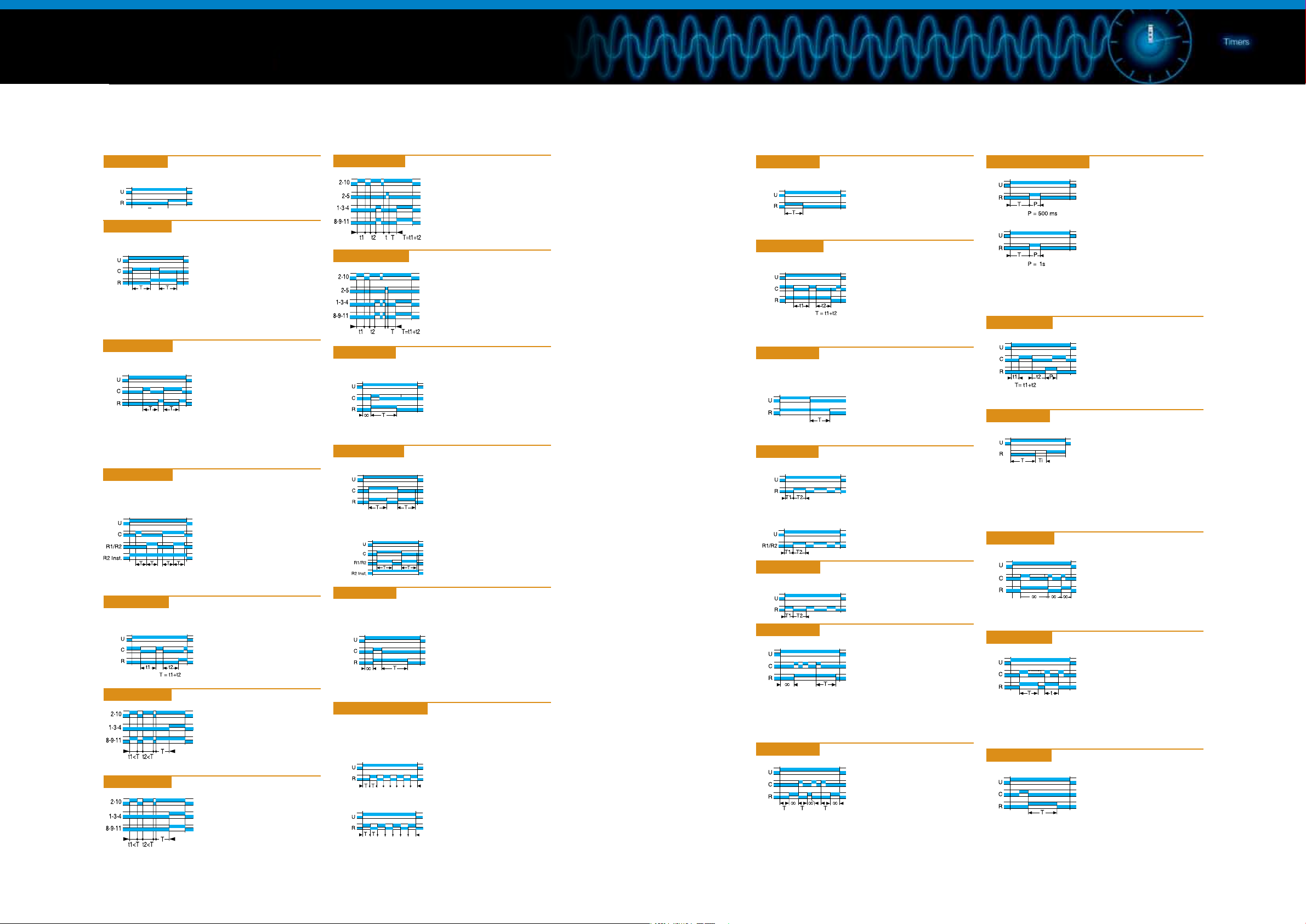
U : Supply
R : Output relay
or load
T : Timing
: Innity
∞
C (Y1) : Command
Function diagrams
Generic functions
• A function: Delay on energisation
1 relay
Single shot timing which starts
on energisation.
• Ac function: Timing after closing and opening
of control contact
1 relay
After energisation, closing of the
control contact results in starting
of the time delay T.
Output relay "R" (or the load)
changes state at the end of
this time delay. After opening of
contact C (Y1), relay "R" drops out
after a second time delay T.
• Ad function: Delay on energisation
1 relay
(cannot be reset)
After energisation, a control pulse
or latching contact starts timing.
At the end of timing, the output
is excited. The output will be reset
when a new control pulse or
latching contact occurs.
• Ah function: Single shot flip-flop
2 timers or
2 relays including
1 instantaneous
(cannot be reset)
After energisation, a control pulse
or latching contact starts timing.
At the end of timing, the output is
excited. The time delay is then
reset. At the end of this new time
delay, the output reverts to its initial
value.
• At function: Timing on energisation
with memory
1 relay
Adds up the opening time
of a contact.
Output relay "R" (or the load)
changes state at the end of timing.
• A1 function: Delay on energisation
1 timer
1 instantaneous relay
• A2 function: Delay on energisation
2 timers.
• AM function: Delay on energisation
Latching during the time delay.
• AMt function: Delay on energisation
Latching during and after
the time delay.
• B function: Timing on impulse (one shot) -
Shaping (cannot be reset)
1 relay
After energisation, an impulse
(≥ 50 ms) or a latching contact
causes a change in state of the
output relay "R" (or the load)
which drops out at the end
of timing.
• Bw function: Pulse output (adjustable)
1 relay
On closing and opening
of the control contact C (Y1),
the output relay "R" (or the
load) changes state for as long
2 timers or
2 relays including 1 instantaneous
as the time delay lasts.
• C function: Timing after impulse
True delay off
(without auxiliary power supply)
1 relay
After energisation, closing of the
control contact C (Y1) results in
the change of state of output relay
"R" (or the load).
Timing will only start when this
contact opens.
• D or Di functions: Symmetrical flashing
Repetitive cycle which alternately sets the output relay "R"
(or the load) to operating and rest position for equal periods
of time.
1 relay
D function:
The cycle starts with relay
"R" in rest position.
1 relay
Di function:
The cycle starts with relay
"R" in operating position.
U : Supply
R : Output relay
or load
T : Timing
: Innity
∞
C (Y1) : Command
• H function: Timing on energisation -
Pulse output (adjustable)
1 relay
On energisation, the output relay
"R" (or the load) changes state, and
stays there for the whole duration of
the time delay and drops out at the
end of the single shot cycle.
• Ht function: Delay on energisation with memory
1 relay
Adds up the total opening time
of a contact.
On energisation, the output relay
"R" (or the load)
changes state, and stays there for
the whole duration of the time delay
and drops out at the end of the
single shot cycle.
• K function: Delay on de-energisation
True delay off
(without auxiliary power supply)
1 relay
On energisation, the output relay
"R" (or the load) changes state.
On de-energisation timing starts
and the relay "R" will only drop out
at the end of this time delay.
• L function: Asymmetrical flashing
1 relay
Repetitive cycle with two times
which can be set independently.
different state of the output relay
2 timers or
2 relays including
"R" (or the load).
1 instantaneous
Each time delay alternates with a
Note: The cycle starts with
the relay
"R"
in the rest position.
• Li function: Asymmetrical flashing
1 relay
Repetitive cycle with two times
which can be set independently.
• N function: "Safe-guard"
On the rst control pulse,
the output is excited.
If the interval between two
impulses is longer than the timing
value, this occurs normally and the
output relay "R" (or the load)
will change state at the end of
timing. Otherwise, relay "R" stays
in its original state until the
condition is fullled.
• O function: "Delayed safe-guard"
On energisation, a rst timer
runs and the output relay "R"
(or the load) changes state.
On the appearance of a control
pulse, relay "R" returns to its initial
the time interval between 2 impulses is less than the timing value.
Otherwise, relay "R" will change state at the end of timing.
position and stays there as long as
• P and Pe functions: Impulse counter (delay on)
P function:
Timing starts on energisation.
At the end of timing, the output
relay "R" (or the load) changes
state for approximately 500 ms.
Pe function:
On energisation.
At the end of timing, the output
relay "R" (or the load) changes
state for approximately 1 s.
• Pt function: Impulse counter (delay on)
Adds up the total opening time
of a contact.
At the end of timing, the output is
excited for approximately 500 ms.
• Q function: "Star-delta" starting
On energisation, the "star"
contact closes instantaneously
and timing starts.
At the end of timing the Ti "star"
contact opens. After a pause
of 40 to 100 ms the "delta" contact
closes.
• TL function: Impulse relay
After energisation, a control pulse
or latching contact closes the
relay. A second control pulse
opens the relay.
• Tt function: Timed impulse relay
After energisation, a control pulse
or latching contact closes the relay
and starts timing.
The relay opens at the end of timing
or on a second control pulse.
• W function: Timing after pulse on control contact
After energisation, opening of the
control contact results in a change
in the state of output "R" (or the
load) and timing starting.
 Loading...