

Crouzet SMI22 CANopen, SQ75 CANopen 80350, SQ75 CANopen 80360, SQ75 CANopen 80370, SMI22 CANopen Series Product User Manual
...Page 1

SMI22 CANopen
C.MO.SAV.00022.FR_V3 Page 1/24
September 3rd, 2018
PRODUCT USER MANUAL
SMI22 CANopen
Important Notes
• This manual is part of the product.
• Read and follow the instructions in this manual.
• Keep this manual in a safe place.
• Give this manual and any other documents relating to the product to anyone that uses the product.
• Read and be sure to comply with all the safety instructions and the section "Before you Begin -
Safety-Related Information" in the document “Safety User Manual”
• Please consult the latest catalogue to find out about the product's technical specifications.
• We reserve the right to make modifications without prior notification.
Page 2

SMI22 CANopen
C.MO.SAV.00022.FR_V3 Page 2/24
September 3rd, 2018
Table of Contents
1. Introduction ................................................................................................................................................ 5
1.1. Motor Family ..................................................................................................................................... 5
1.2. Characteristics .................................................................................................................................. 5
1.3. Identification Label ............................................................................................................................ 5
1.4. Product Coding ................................................................................................................................. 6
1.5. Standards and concepts ................................................................................................................... 7
2. Options and Accessories ........................................................................................................................... 8
2.1.1. Holding brake ........................................................................................................................... 8
2.1.2. Gearboxes ................................................................................................................................ 8
2.1.3. Other ......................................................................................................................................... 8
2.1.4. Starter Kit .................................................................................................................................. 8
3. Precautions for use concerning the mechanics ......................................................................................... 9
3.1. Data specific to the motor shaft ........................................................................................................ 9
3.2. USB Connector ............................................................................................................................... 10
3.3. Fixings ............................................................................................................................................. 11
4. Product overview ..................................................................................................................................... 11
4.1. Description of the Product ............................................................................................................... 11
4.2. SMI22 CANopen Control Electronics .............................................................................................. 12
4.3. "DCmind-Soft + CANopen" PC Parameter-Definiti on S of tware ...................................................... 13
5. Technical Specifications .......................................................................................................................... 14
5.1. Electrical Data ................................................................................................................................. 14
5.2. Generic Data ................................................................................................................................... 14
5.3. Logic M16 connector ....................................................................................................................... 15
5.4. Power Supply M16 connector ......................................................................................................... 16
5.5. CAN communication M12 connector .............................................................................................. 16
6. Motor electrical connection ...................................................................................................................... 18
6.1. Power Connection ........................................................................................................................... 18
6.1.1. Ballast Circuit .......................................................................................................................... 18
6.1.2. EMC Protection ...................................................................................................................... 19
6.1.3. Earth connection ..................................................................................................................... 19
6.2. Protection ........................................................................................................................................ 20
6.2.1. Voltage Protection .................................................................................................................. 20
6.2.2. Temperature Protection .......................................................................................................... 21
6.2.3. Current Limiting ...................................................................................................................... 21
6.3. Input/Output Connection ................................................................................................................. 22
6.3.1. Equivalent Input Diagram ....................................................................................................... 22
6.3.2. Equivalent Output Diagram .................................................................................................... 23
6.4. Terminology and Abbreviations....................................................................................................... 24
Page 3

SMI22 CANopen
C.MO.SAV.00022.FR_V3 Page 3/24
September 3rd, 2018
Page 4

SMI22 CANopen
C.MO.SAV.00022.FR_V3 Page 4/24
September 3rd, 2018
About This Manual
This manual applies to SQ75 CANopen brushless products:
• 80350,
• 80360,
• 80370,
And all gearboxes adaptation.
Reference source for manuals
The manuals can be downloaded from our website at the following address:
http://www.crouzet-motors.com/
Units
SI units are the default values.
Risk Categories
In this manual, safety instructions are identified by warning symbols.
Depending on how serious the situation is, the safety instructions are split into 3 risk categories.
DANGER
DANGER indicates a directly dangerous situation which, if the
instructions are not followed, will inevitably lead to a serious or fatal
accident.
WARNING
WARNING indicates a possibly dangerous situation which, if the
instructions are not followed, will in some cases lead to a serious or
fatal accident or cause damage to equipment.
CAUTION
CAUTION indicates a potentially dangerous situation which, if the
instructions are not followed, will in some cases lead to an accident or
cause damage to equipment.
Page 5

SMI22 CANopen
C.MO.SAV.00022.FR_V3 Page 5/24
September 3rd, 2018
1. INTRODUCTION
1.1. Motor Family
SQ75 brushless motors are brushless DC motors, with a control circuit board integrated in the motor.
1.2. Characteristics
SQ75 brushless motor s are intelligent servomotors for speed, pos ition and torqu e control appl ications. They
can be configured via a Human-Machine Interface (HMI) with CANopen or USB communication bus.
They are equipped with 3 i ndustria l c onnec tors, 1 for po wer, 1 for the contr ol signals and 1 f or th e CANo pen
communication.
1.3. Ide nti fication Label
The label contains the following data:
Page 6

SMI22 CANopen
C.MO.SAV.00022.FR_V3 Page 6/24
September 3rd, 2018
1.4. Product Coding
Three
firsts
digits
4th digit 5th digit 6th digit 7th digit 8th digit
803 5 = Rotor 37,5mm
0 : direct motor
IP69
0 : with integrated drive
0 à 3: SMi22 CAN (if 6th digit = 0 ou 1)
from 0 to 9
6 = Rotor 50mm D : P72 1 : with integrated drive + brake
4 à 6: SMi22 (without CAN) (if 6th digit = 0 ou 1)
7 = Rotor 75mm E : P81 4 : hall effects
2 : RAD20 5 : Hall effects + brake
Page 7

SMI22 CANopen
C.MO.SAV.00022.FR_V3 Page 7/24
September 3rd, 2018
1.5. Standards and concepts
The product is ROHS confirmed following European Directive 2011/65/CE. Following this confirmation, the
product is CE marked.
The electrical design follows the IEC 60335-1 and IEC 60950-1 standards.
Page 8

SMI22 CANopen
C.MO.SAV.00022.FR_V3 Page 8/24
September 3rd, 2018
2. OPTIONS AND ACCESSORIES
The motors can be supplied with options, such as:
• Different gearboxes
• A failsafe holding brake
• Different motor output shaft versions
2.1.1. Holding brake
SQ75 brushless motors can be equipped as standazromechanical brake.
The holding brake is designed to lock the motor shaft in a de-energized state.
The holding brake is not a safety function.
A motor with a holding brake needs a corresponding c ontrol logic which releases the ho lding brake at the
start of the rotation movement, locking the motor shaft in time when the motor stops.
Nota : Outputs are able to drive the electromechanical brake.
Nota : Motor has to be completely stopped before activation of the brake.
2.1.2. Gearboxes
SQ75 brushless motors can be equipped with different types of gearbox.
The gearboxes off ered as standard in the c atalogue are planetar y gearboxes which com bine compact si ze
and robust design, and worm gearboxes that allow a shaft output at right-angles to the motor shaft.
2.1.3. Other
Other types of adaptation are possible on request, please contact the sales department.
2.1.4. Sta rter Kit
This kit consists of:
- a 2-meter long micro USB B to USB A (MOLEX 68784-0003) connecting cable 27 526 005
- a power cable : this cable can be obtained by ordering part number 79 298 664
- an I/O cable : this cable can be obtained by ordering part num ber 79 5 13 106
- a CAN cable M12 M/F : this cable can be obtained by ordering part number 27 358 015
- a bus terminating resistor : this resistor can be obtained by ordering part number 27 358 014
- a D-Sub bus connector 27 358 017
- an USB to CAN converter (PEAK System reference IPEH-002021) 27 358 016
- an USB stick containing the "DCmind Soft + CANopen Interface" parameter-definition software and
installation drivers for this HMI.
- A T (F-M/F) CAN connector 27 358 020
This starter kit can be obtained by ordering part number 79 5 13 105
Page 9

SMI22 CANopen
C.MO.SAV.00022.FR_V3 Page 9/24
September 3rd, 2018
3. PRECAUTIONS FOR USE CONCERNING THE MECHANICS
3.1. Data specific to the motor shaft
WARNING
MOTOR MECHANISM
Exceeding the maximum permissible forces on the shaft leads to rapid
bearing wear, a broken shaft or damage to any accessories (encoder,
brake, etc.)
• Never exceed the maximum axial and radial forces.
• Protect the shaft from any impact.
• When press-fitting components, do not exceed the maximum
permissible axial force.
Failure to comply with these precautions can result in death,
serious injury or damage to equipment.
Radial load on the shaft
The application point X of the radial force F depends on the motor size.
This information appears in the motor technical data sheet.
The maximum axial and radial loads must not be applied simultaneously.
F
x
Page 10

SMI22 CANopen
C.MO.SAV.00022.FR_V3 Page 10/24
September 3rd, 2018
3.2. USB Connector
The motor is equipped with a micro USB conn ector, which can be acc essed by removing the s topper from
the housing.
The stopper prevents penetration of foreign bodies or fluids inside the motor.
The stopper prevents fingers or any inappropriate object making contact with the micro USB connector.
For any other connector, when not used, stoppers have to be mounted.
WARNING
UNEXPECTED MOVEMENT DUE TO ELECTROSTATIC DISCHARGES
Electrostatic discharges (ESD) on the micro USB connector can, in
some cases, lead to deterioration or destruction of some system
components and generate unexpect ed motor operation.
• Never touch the connector with your fingers or any inappropriate
object.
Failure to comply with these precautions can result in death,
serious injury or damage to equipment.
CAUTION
LOSS OF SEALING
The stopper ensures the motor is sealed.
• Replace it after completing parameter definition.
• Make a visual check to ensure it is in place.
Failure to comply with these precautions can result in injury or
damage to equipment.
Housing
USB stopper
Page 11
SMI22 CANopen
C.MO.SAV.00022.FR_V3 Page 11/24
September 3rd, 2018
3.3. Fixings
Fixing of the product has to be done by using 4 M6 screws with a screwing torque of 7N.m.
4. PRODUCT OVERVIEW
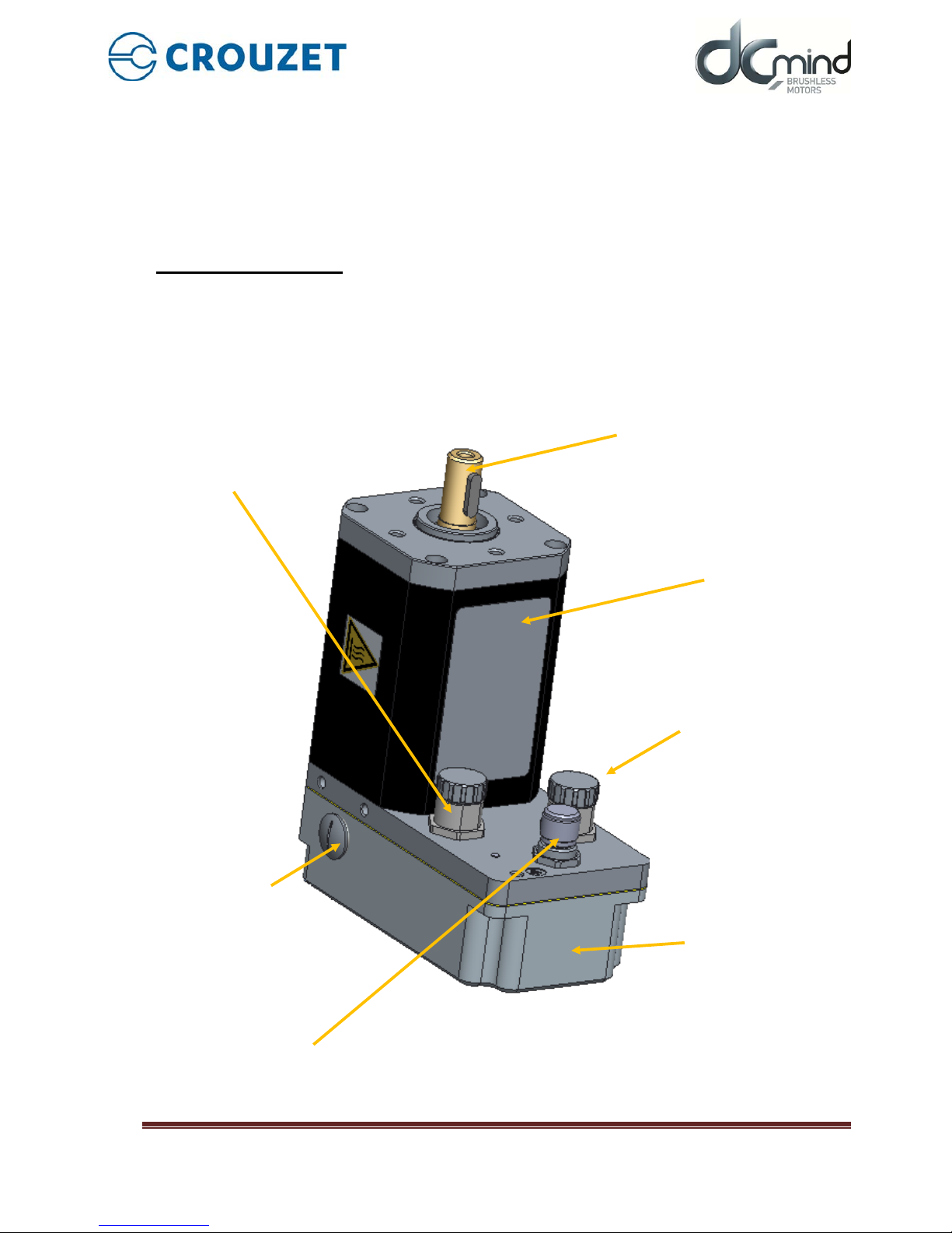
4.1. Description of the Product
Label
18-pin logic M16 connector
(Inputs/Outputs)
3-pin power supply M16
connector
Output shaft
CAN communication
M12 connector
SMI22 CANopen integrated
electronics
USB-B micro-connector
(Parameter definition via HMI)
Page 12

SMI22 CANopen
C.MO.SAV.00022.FR_V3 Page 12/24
September 3rd, 2018
4.2. SMI22 CANopen Control Electronics
The SQ75 CANopen electronic control board contains the control electronics for a brushless motor,
integrated in the motor body.
This electronics is used for:
• Power switching of the motor in sine mode (field-oriented control (FOC)) or trapezoidal mode.
• Position-Speed-Torque and Current control algorithms.
• CANopen CiA 301 standard – Application layer and communication profile
• CANopen CiA 402 standard – Drive and motion control device profile
• Use of preconfigured programs which can perform numerous routine applications (DCmind programs).
• Management of different types of operation:
o "Stand-alone" motor without external PLC.
o Use with other motors incorporating SMI22 or SMI21 electronics.
o Use with a programmable controller, with the SMI22 simplifying motor management.
• The interface with parameter-definition software installed on the PC:
o Easy to use, even by a laym an, thanks to simplified application pro grams that are quick to
get up and running.
o Wide choice of expert programs covering a wide range of applications.
o CAN connection via a commercially-available standard cable (can be supplied on request).
o USB connection via a commercially-available standard cable (can be supplied on request).
• Management of 6 inputs,4 outputs and 2 STO inputs (for safety) to control the motor:
o 2 inputs that can be configured for 0-10 V 10-bit analog or PWM or digital control
o 4 digital inputs
o 2 isolated differential STO inputs (4 leads)
o 1 output that can be configured as PWM or frequency or digital
o 1 output that can be configured as PWM or digital
o 2 digital outputs
As standard, the motors have an internal encoder with 4096 points per revolution that can reach high
positioning and control resolutions.
Note : For res et the motor by CANOpen (e.g. when Bootload er mode is requir ed), index 0x2FF F sub index
0x00 has to be set at value=0x64747372.
Page 13

SMI22 CANopen
C.MO.SAV.00022.FR_V3 Page 13/24
September 3rd, 2018
4.3. "DCmind-Soft + CANopen" PC Parameter-Definition Software
This software can be downloaded from the Internet at the following address: http://www.crouzet-motors.com/
It can also be supplied as a kit, see "Starter Kit" section.
This "DCmind-Sof t + CANopen" s oftware is needed th e first time the m otor is used and for debuggi ng if you
don’t have a CANopen master.
It is used for:
• Selecting the motor operating program:
o Position
o Speed
o Torque
o Homing
o Quick and easy starting using preprogrammed applications.
o Use of "expert" programs that provide access to all settings.
• The various settings needed for the application to work correctly.
• Updating the "firmware" motor program using the bootloader function.
For more information, see the HMI user manual dedicated for the “DCmind Soft + CANopen”
Page 14

SMI22 CANopen
C.MO.SAV.00022.FR_V3 Page 14/24
September 3rd, 2018
5. TECHNICAL SPECIFICATIONS
5.1. Electrical Data
Maximum Product Specifications
Parameters
Value
Unit
Supply voltage V
DC_MAX
75
V
Maximum current I
DC_MAX (2seconds)
75
A
Maximum input voltage V
IN_MAX
90
V
Maximum output voltage V
OUT_MAX
24
V
Maximum output current I
OUT_MAX
10
mA
Operating Specifications
Parameters
Min
Typical
Max
Unit
Supply voltage VDC
9
24 / 32 / 48
75
V
Current IDC
-
15 - A
Motor consumption when stopped without holding
W0
- 1 - W
Input Specifications
Parameters
Min
Typical
Max
Unit
Input impedance In1 to In4
-
200 - kΩ
Input impedance AN5 to AN6
-
107.2
-
kΩ
Low logic level on inputs In1 to In4
-90 - 2.4
V
High logic level on inputs In1 to In4
4.5 - 90
V
Low logic level on inputs AN5 to AN6
-90 - 2
V
High logic level on inputs AN5 to AN6
4.6 - 90
V
Low logic level on STO1 & 2
-2 - 4
V
High logic level on STO1 & 2
4.6 - 75
V
CAN Low level
0.5
1.5
2.25
V
CAN High level
2.75
3.5
4.5
V
Output Specifications
Parameters
Min
Typical
Max
Unit
Low logic level on outputs Out1 to Out4 V
OL
RL = 4 K7Ω, VDC = 24 V
- 5 10 mV
High logic level on outputs Out1 to Out4 V
OL
RL = 4 K7Ω, VDC = 24 V = voltage supply added from
eventual rejective voltage
- - 24 V
5.2. Generic Data
General Specifications
Parameters
Value
Unit
Ambient motor temperature
-30 to +70
°C
Insulation class (compliant with directive IEC 60085)
E
/
Ingress protection (excluding output shaft)
IP67 + IP69
/
CANopen compliance
CiA DS 301 and CiA DS 402
/
Page 15
SMI22 CANopen
C.MO.SAV.00022.FR_V3 Page 15/24
September 3rd, 2018
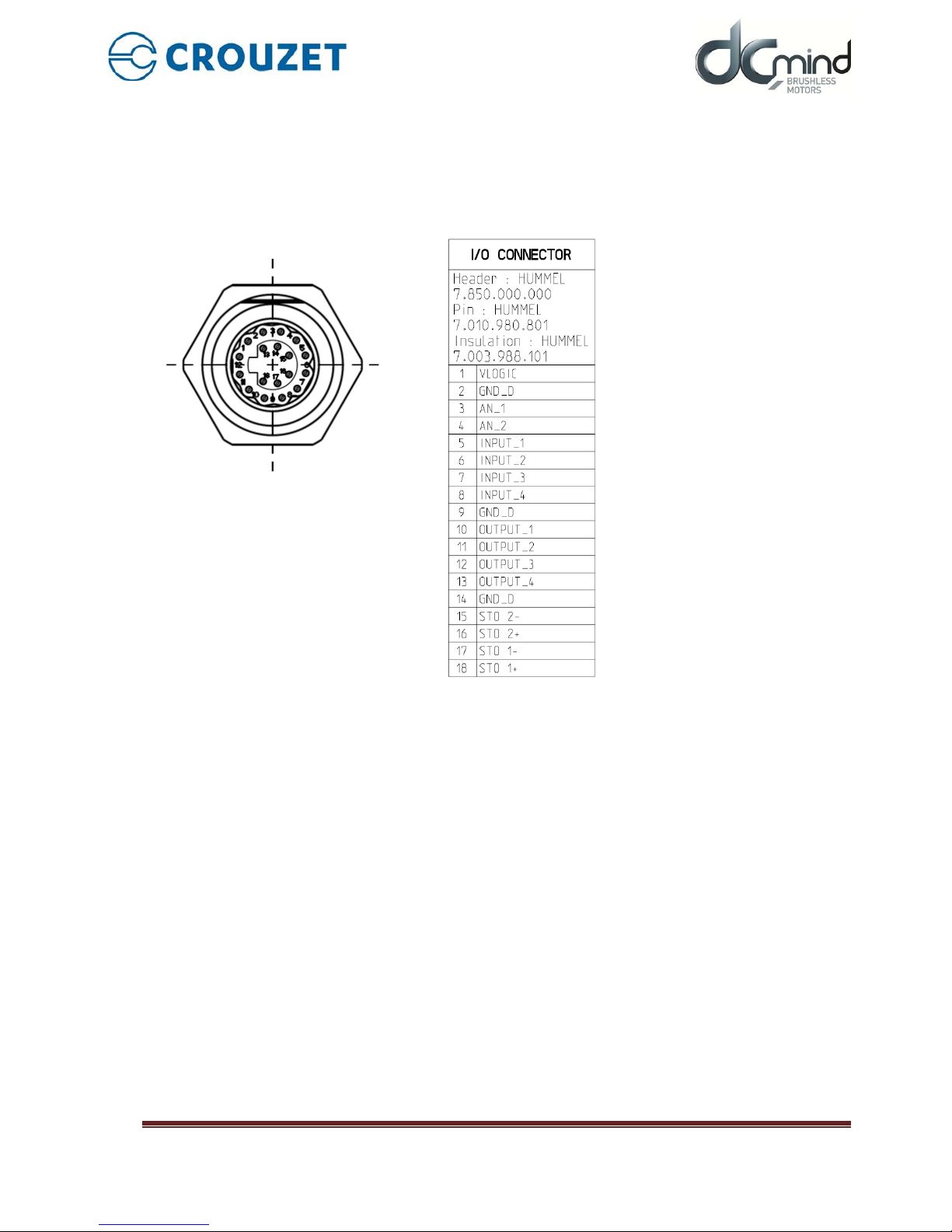
5.3. Logic M16 connector
It’s a M16 18-pin industrial male connector
Recommended AWG for the associated cable: AWG24 for wires inside a shielded cable.
(See part “Starter Kit” of this document).
With cables more than 3 m long, tests must be performed in situ.
Page 16

SMI22 CANopen
C.MO.SAV.00022.FR_V3 Page 16/24
September 3rd, 2018
5.4. Power Supply M16 connector
It’s a M16 3-pin industrial male connector.
Recommended AWG for the associated cable: AWG14 for wires inside a shielded cable.
(See part “Starter Kit” of this document).
With cables more than 3 m long, tests must be performed in situ.
5.5. CAN communication M12 connector
It’s a M12 5-pin industrial male connector with standard pinout according to CiA 303-1 recommendations.
Recommended AWG for the associated cable: AWG24 for wires inside a shielded cable.
(See part “Starter Kit” of this document).
Note that the maximum baud rate depends of the cable length.
Page 17

SMI22 CANopen
C.MO.SAV.00022.FR_V3 Page 17/24
September 3rd, 2018
5.6. Connectors part numbers
MOTOR
CABLE
I/O
connector
Panel
connector
HUMMEL
7.850.000.000
All HUMMEL
M16
AWG24
cable
Insert
HUMMEL
7.003.988.101
HUMMEL
7.003.988.102
Contact
HUMMEL
7.010.980.801
HUMMEL
7.010.980.802
Supply
connector
Panel
connector
HUMMEL
7.850.000.000
AWG14
cable
Insert
HUMMEL
7.003.983.101
HUMMEL
7.003.983.102
Contact
HUMMEL
7.010.982.001
HUMMEL
7.010.982.002
CAN connector MOLEX M12/PG9 1200708205
any compatible connectors
(i.g : Weidmüller SAIL-
M12GM12G-5S3.0U)
Page 18
SMI22 CANopen
C.MO.SAV.00022.FR_V3 Page 18/24
September 3rd, 2018
6. MOTOR ELECTRICAL CONNECTION
These motors are not intended to be directly connected to the line supply.
It is the responsibility of the installer to define the electrical protections to be implemented according to the
regulations applicable to the end product range of application.
We recommend the use of fuses in accordance with UL248-5 Test 1.3 & 5.
Supply power must be a stabilized power supply with double electrical insulation.
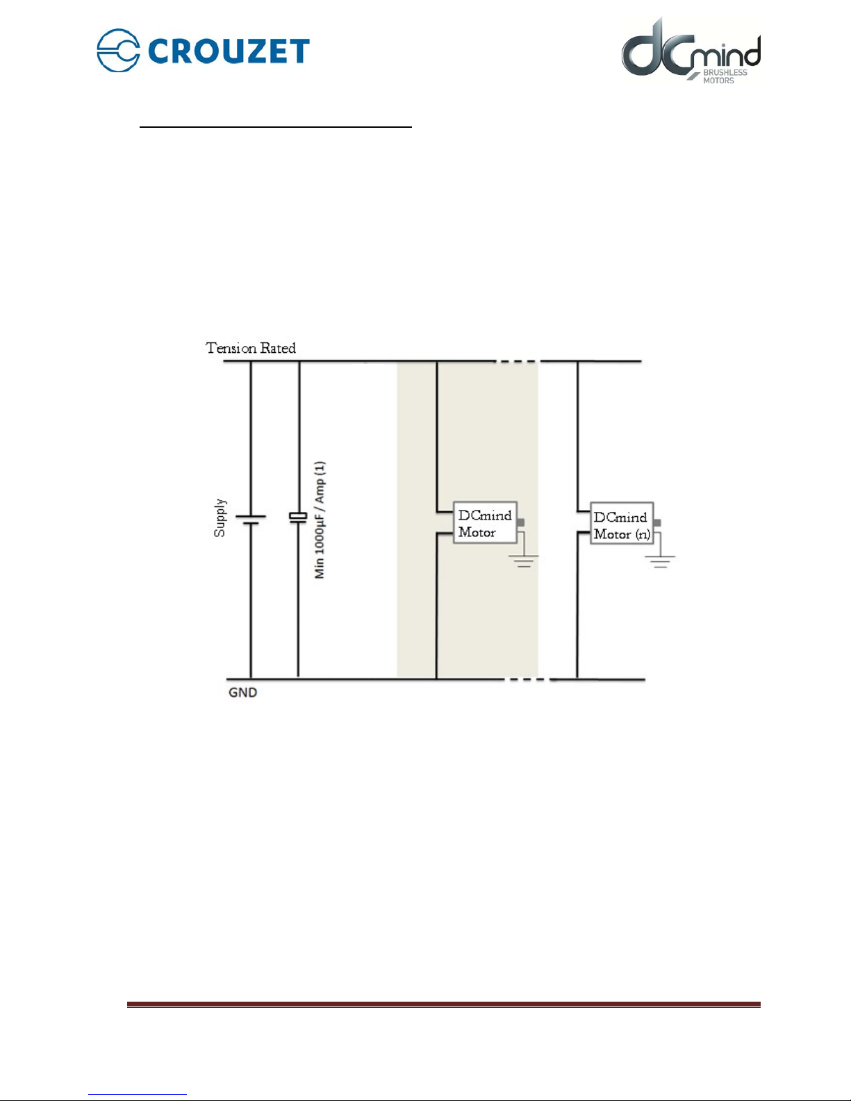
6.1. Power Connection
We recommend grounding the motor housing.
Power connection diagram.
(1)
Include capacitors to smooth out inrush currents. Recommended value 1000 µF/A drawn.
6.1.1. Balla s t Circuit
When the motor brakes, the kinetic energy stored in the inertias during rotation is returned to the power
supply and generates a vo ltage surge. This voltage surge can be destructi ve for the motor or for devices
connected to the power supply.
In the event of frequent brak ing, an ext ernal ball ast resistor must be u sed, all the cir cuitr y is integrated in
the product. Ballast parameters are available through CANopen communication.
For more information, see the HMI user manual dedicated for the “DCmind Soft + CANopen”
It is always necessary to conduct tests to check what size it should be.
Page 19

SMI22 CANopen
C.MO.SAV.00022.FR_V3 Page 19/24
September 3rd, 2018
6.1.2. EMC Protection
In order to ensure that the product is compatible with EMC standards IEC 61000-6-1, IEC 61000-6-2, IEC
61000-6-3, IEC 61000-6-4, EN55022 Class B we recommend:
- Connecting the motor to ground while limiting length of the grounding strip,
- Adding capacitors on the main power supply.
We recommend 1000 µF per amp drawn.
-
6.1.3. Earth connection
A taped hole on the housing is dedicated to the earth connection. Use M5x6mm screw class 8.8 to connect
product with a screwing torque of 4N.m±15%. Use AWG12 gauge lead for earth connection.
Page 20

SMI22 CANopen
C.MO.SAV.00022.FR_V3 Page 20/24
September 3rd, 2018
6.2. Protection
DANGER
PROTECTION
The product has in ternal protection de vices that switch off the
motor power suppl y when activated. As the motor is no longer
controlled, driving loads can decrease.
• The system manufac tur er is res pons ib le f or c om pl ying w ith all
the applicable safety rules in the event of product failure.
Failure to comply with these precautions will result in
death or serious injury.
6.2.1. Voltage Protection
The product incorporates protection against voltage surges and undervoltages.
Protection against voltage sur ges :
The voltage surge threshold can be set in the HMI.
When the supply voltage exceeds the threshold, the product automatically switches to ERROR mode. In
ERROR mode the motor is no longer controlled.
To reset the motor:
- The supply voltage must be at least 1 V below the threshold value.
- It is necessary to pass in DISABLE mode then ENABLE mode.
Protection against undervol tages :
The under voltage threshold can be set in the HMI.
When the supply volta ge falls below this threshold, the pro duct automaticall y switches to ERRO R mode. In
ERROR mode the motor is no longer controlled.
To reset the motor:
- The supply voltage must be at least 1V higher than the threshold value
- It is necessary to pass in DISABLE mode then ENABLE mode.
Page 21

SMI22 CANopen
C.MO.SAV.00022.FR_V3 Page 21/24
September 3rd, 2018
6.2.2. Temperature Protection
• The product incorpora tes a first temperature protec tion in the form of a tem perature sensor on the
motor pilot control card.
Temperature protection:
The under and over temperature thresholds can be set in the HMI (set at -40°C and +110°C by default).
In this case, when the internal temperature exceeds 110°C (or is below than -40°C), the product
automatically switches to ERROR mode. In ERROR mode the motor is no longer controlled.
To reset the motor:
- The temperature must be between the 2 thresholds.
- The motor inputs must be set to DISABLE mode then ENABLE mode.
• The product incorporates second temperature protection with 3 thermistors into the stator coils.
Temperature protection:
In this case, when the stator temperature exceeds 120°C, the product automatically switches to ERROR
mode. In ERROR mode the motor is no longer controlled.
To reset the motor:
- The temperature must be under 120°C.
- The motor inputs must be set to DISABLE mode then ENABLE mode.
- .
6.2.3. Current Limiting
The product incorporates internal current limiting. This limiting directly affects the motor in terms of hardware.
If this limit is reached, it results in a loss of motor performance.
This product is not designed to operate continuously with this limiting (see the "Electrical Data" section).
Page 22

SMI22 CANopen
C.MO.SAV.00022.FR_V3 Page 22/24
September 3rd, 2018
6.3. Input/Output Connection
6.3.1. Equivalent Input Diagram
Page 23

SMI22 CANopen
C.MO.SAV.00022.FR_V3 Page 23/24
September 3rd, 2018
6.3.2. Equivalent Output Diagram
Page 24

SMI22 CANopen
C.MO.SAV.00022.FR_V3 Page 24/24
September 3rd, 2018
6.4. Terminology and Abbreviations
Encoder
Mounted on the motor, the angular position sensor provides frequency pulses proportional to the motor
speed.
Degree of protection
The degree of protection is a standard definition used for electrical equipment that aims to describe the
protection against penetration of solids and liquids inside the motor casing (for example IP54M). The M
indicates that the tests are conducted with the motor running.
This value cannot take account of the seal around the output shaft, for which the installer must take
responsibility.
Axial forces
Longitudinal traction or compression forces affecting the shaft.
Radial forces
Radial forces affecting the shaft.
Direction of rotation
Positive or negative direction of rotation of the motor shaft. The positive direction of rotation is clockwise
rotation of the motor shaft, when looking at the motor from the output shaft.
Nominal speed
Motor speed of rotation when nominal torque is applied.
Nominal current
Current drawn by the motor when nominal torque is applied.
Nominal torque
Maximum applicable torque in continuous duty on the motor shaft.
Firmware
Control software embedded in the motor.
Bootloader
Function available in the HMI which can be used to update the firmware.
Commonly used abbreviati ons:
HMI: Human-Machine Interface
SMI22: Trade name of the new CROUZET brushless range
Homing: Initialization phase for finding the limits
AON: Type of digital inputs/outputs (All Or Nothing)
PWM: Pulse Width Modulation
FWD: Forward
REV: Reverse
NO: Normally Open
NC: Normally Closed
EMC: Electromagnetic Compatibility
 Loading...