

Page 1
Subminiature Switches Series 83 170 DIN 41 635 B
General specifications
Layout Components
Material
- Case : polyester UL 94 VO
- Button : glass-filled polyamide
- Contacts : AgNi,
gold-plated AgNi (dual-current)
- Terminals : copper-nickel
Actuators
- flat : stainless steel
- roller : stainless steel with polyamide roller
Approvals:
NF - UL - cUL
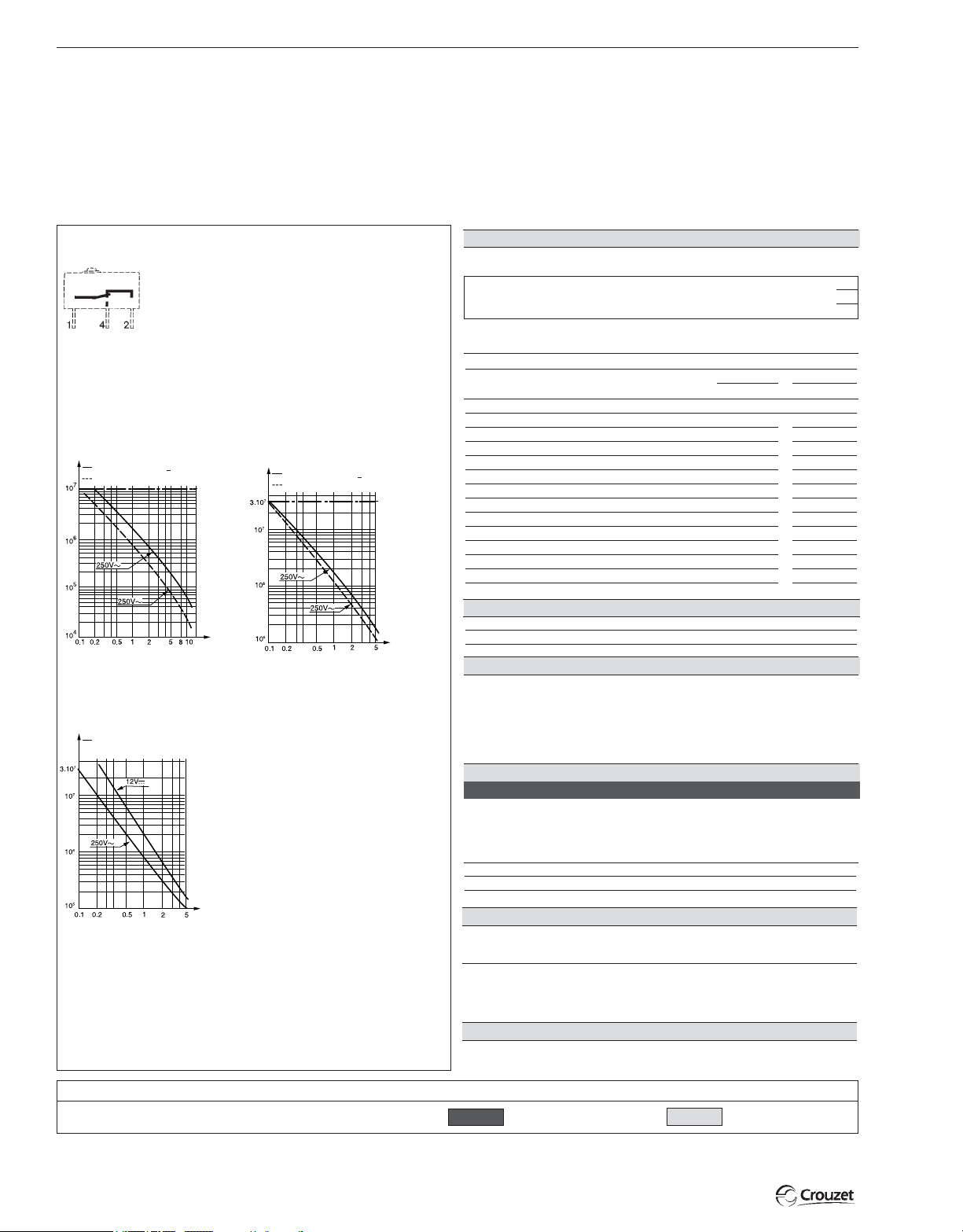
Operating curve
For type 83 170 0 For type 83 170 4
Number of
operations
Resistive circuit:
Inductive circuit
L
c
= 5 ms
R
{
a
cos
ϕ = 0.8
Mechanical
life
Rating in
Amps
Number of
operations
Resistive circuit:
Inductive circuit
For type 83 170 9
Number of
operations
Resistive circuit:
Types
1
Part numbers for standard products (no lever) terminal type
2
3
Features
Electrical characteristics
Current rating at 250 V
Nominal A
Thermal A
Mechanical characteristics
Operating force - max. N (oz.)
Release force - min. N (oz.)
Total travel force - max. N (oz.)
L
c
= 5 ms
R
a
{
cos
ϕ = 0.8
Mechanical
life
Permitted overtravel force - max. N (oz.)
Maximum rest position mm (in.)
Tripping point mm (in.)
Differential travel mm (in.)
Overtravel - min. mm (in.)
Ambient operating temperature °C
Mechanical endurance Operations
Contact gap mm (in.)
Weight g (oz.)
Contact type
Rating in
Amps
C (Form C) SPDT
B (Form B) SPNC not available in PC terminals
A (Form A) SPNO not available in PC terminals
Connections
Mechanical
life
Rating in
Amps
Model 83 170 9 is designed to operate equally well on dual-current
(1 mA 4 V minimum) or medium-current (5 A maximum) circuits.
However, a given product should only be used to switch one type of
circuit during its working life.
For other forces, actuators, connections and temperatures,
please consult us.
Products and specifications subject to change without notice.
3/6
Actuators and mounting positions
Part numbers for standard actuators
Actuators – Length mm (in.)
Mounting positions
Coefficient
Tripping point mm (in.)
Mounting positions
Except where otherwise indicated, actuators are supplied unmounted.
For factory mounting, specify mounting position L or R.
–
To calculate force : take the force quoted for the switch and divide by
the coefficient given in the table.
–
To calculate travel : take the travel quoted for the switch and multiply
by the same coefficient.
Mounting accessories for PCB mounting: 5 / 6 / 7 / 8
See page 3/9.
Other information
Normally stocked items
Catalog products produced
to order
Page 2
1
83170.0
831700C1.0
831700C2.0
831700C3.0
High current
10
12.5
1.5 (5.3)
0.3 (1)
1.8 (6.3)
10 (35.3)
9.2 (.36)
±0.3
8.4
0.15 (.006)
0.5 (.02)
-20 to130 (-4 to 266)
10
0.4 (.016)
1.7 (.06)
C
B
A
±.01
(.33
)
7
83170.4
831704C1.0
831704C2.0
831704C3.0
Standard
5
6
0.6 (2.2)
0.1 (.04)
1 (3.5)
10 (35.3)
9.2 (.36)
±0.3
7
(.33
±.01
)
8.4
0.15 (.006)
0.5 (.02)
-20 to130 (-4 to 266)
3.10
0.4 (.016)
1.7 (.06)
C
B
A
83170.9
831709C1.0
831709C2.0
831709C3.0
Low current
0.1
0.6 (2.2)
0.1 (.04)
1 (3.5)
10 (35.3)
9.2 (.36)
±0.3
7
(.33
±.01
)
8.4
0.15 (.006)
0.5 (.02)
-20 to130 (-4 to 266)
3.10
0.4 (.016)
1.7 (.06)
C
B
A
83170.4 SP 4967
831704C2.MBSP
831704C3.MBSP
831704C1.MBSP
High force
5
6
1.5 (5.3)
0.3 (1)
1.8 (6.3)
10 (35.3)
10.8 (.425)
±0.3
9.9
0.15 (.006)
0.5 (.02)
-20 to130 (-4 to 266)
10
0.4 (.016)
1.7 (.06)
C
B
A
±.01
(.39
)
6
83170.4
831704C1.MB
831704C2.MB
831704C3.MB
Standard
5
6
0.6 (2.2)
0.1 (.04)
1 (3.5)
10 (35.3)
10.8 (.425)
±0.3
9.9
0.15 (.006)
0.5 (.02)
-20 to130 (-4 to 266)
10
0.4 (.016)
1.7 (.06)
C
B
A
±.01
(.39
)
6
83170.9
831709C1.MB
831709C2.MB
831709C3.MB
Low current
0.1
0.6 (2.2)
0.1 (.04)
1 (3.5)
10 (35.3)
10.8 (.425)
±0.3
9.9
0.15 (.006)
0.5 (.02)
-20 to130 (-4 to 266)
10
0.4 (.016)
1.7 (.06)
C
B
A
±.01
(.39
)
6
2
3
3
2134 5 6 7 8
79 253 327
A
Flat 170A R18.3 (.72)
(.41
R
1.5
±.05
±0.6
)
9.2
(.36
L
3
±1.2
10.4
79 218 491
D
Screw 170D R20 (.79)
±.24
)
79 253 326
B
Flat 170A R24 (.94)
L
4
±1.2
11.1
79 218 493
L
Transverse roller
Characteristics available upon request.
Type
Switch
1
831700
831704
831709
To order actuators separately, use the 8 digit P/N
Contact Type
2
A
B
C
(.44
79 253 328
C
Flat
170A R41 (1.61)
±.05
)
R
2
±0.6
±.24
9.6
(.38
170L R20 (.79)
)
L
7
13.2
±2.5
(.52
R
3.5
±1.2
10.7
(.42
±.05
±.1
)
MB
To order please specify :
Example : 831700
Connection
3
15
26
37
48
Products and specifications subject to change without notice.
C 2 • C L
4
Example P/N is 831700 SPDT solder terminals “C” actuator mounted on the left.
79 218 454
E
Roller 170E R20 (.79)
L
3
±1.2
±.05
15.4
)
Actuators
AE
BF
CL
DMB
Ø MB SP4967
(.61
4
79 253 329
F
Dummy roller 170F R19.5 (.77)
R
1.5
±0.6
)
14.5
(.57
L
3
±.24
±1.2
13
)
(.51
R
1.5
±0.6
12
(.47
±.24
)
±.05
)
Ø No
Actuator
5
Actuator Position
5
L- Left (Standard)
R - Right
3/7
Page 3

Subminiature Switches DIN 41635 B
OL = 7.6 (.30)
2.4
–0.1
(.09
–.001
R 2.5 (.1)
7.5
–0.2
(.3
.–008
5
–0.1
(.2
–.004
2.4
–0.1
(.1
–.009
9.6
–0.2
(.38
–.008
fl2.
+0.1
0
(fl .0
–.004
0
6.4
–0.2
(.25
–.008
0.5
–0.03 (x3)
(.02
–.001
9.5
–0.1
(.37
–.004
6.35
–0.2
(.25
–.008
8.9
–0.2
(.35
–.008
12.2
–0.2
(.48
–.008
2.2
–0.1
(.09
–.04
fl 2.
–0.1
(.1
–.004
19.8
–0.2
(.78
–.008
4
–0.1
(.157
–.008
=
=
)
)
)
)
)
)
)
)
)
)
)
)
)
)
)
)
7.62
±0.2
(.30
±.008
)
7.62
±0.2
(.30
±.008
)
2.8
±0.1
(.11
±.004
)
Ø1.3
±0.2
0
(.11
±.004
)
7.1
±01
(.28
+.004
)
2.2
±02
0
(.08
+.008
- 0
)
3.7
±02
(.15
+.008
)
1
±0.1
(.04
±.004
)
30°
1.3
±0.05
(.05
±.002
)
3.4
±0.2
(.13
±.008
)
4.5
±0.15
(.18
±.006
)
8.9
±0.1
(.35
±.004
)
Ø 1.6
±0.1
(.06
±.004
)
6.35
±0.1
(.25
±.004
)
1.C 4.NO 2.NC
7.62
±0.1
(.3
±.004
)
Ø 1.6
±0.1
(.06
±.004
)
1.C 4.NO 2.NC
(3x2.54)
(3x1)
7.62
±0.1
(.3
±.004
)
(3x2.54)
(3x1)
4.1
±0.1
(.16
±.004
)
2.4
±0.15
(.1
±.006
)
1.3
±0.1
(.05
±.004
)
4.3
±0.2
(.17
±.008
)
6
±0.15
(.236
±.006
)
3.5
±0.2
(.14
±.008
)
1.3
±0.05
(.05
±.002
)
1
±0.1
(.04
±.004
)
5
±0.2
(2
±.008
)
3.5
±0.2
(.14
±.008
)
1.3
±0.05
(.05
±.002
)
1
±0.1
(.04
±.004
)
5
±0.2
(2
±.008
)
R 3.6
(.14)
Ø 5.5
8.9
±0.2
(.35
±.008
12.2
±0.2
(.48
±.008
)
)
Ø 2.5
±0.1
(.1
±.004
)
19.8
±0.2
(.73
±.008
)
7.5
±0.2
(.3
.±008
5
±0.1
(.2
±.004
)
)
2.4
±0.1
(.1
±.009
±0.2
(.38
±.008
)
)
9.6
0.5
±0.03 (x3)
(.02
±.001
)
Ø2.2
+0.1
0
(Ø .09
±.004
0
)
9.5
±0.1
(.37
±.004
6.35
±0.2
(.25
±.008
)
)
6.4
±0.2
(.25
±.008
)
2.2
±0.1
(.09
±.04
)
Dimensions
83 170 Asymmetric
83 170 Symmetric
83 170 with MB Button
Mounting by M2 screws
Torque : 2 cm daN
mm (in)
Connections
2
Solder
1
.11x.02 Quick Connects
Printed circuit board mounting
Asymmetric Symmetric
3 5 7
4 6 8
3-4
Straight PCB
5-6
Side Output PCB Rear
7-8
Side Output PCB Front
mm (in)
3/8
Products and specifications subject to change without notice.
Page 4

Subminiature Switches DIN 41 635 B
2.9
± 0.1
(.11
± .004)
Sortie côte boîtier : X2
Sortie côte couvercle : X3
Actuators
Actuator mounting positions
5.9
(.23)
11.1
(.44)
R
LR
L
AB C
)
±0.1
±.004
6.3
(.25
13.4
(.53
±0.1
±.004
)
E
mm (in.)
Mounting accessories
Mounting pins
Output on unit side : 5
(.14
3.6
)
±0.1
±.004
6.3
(.25
±0.1
±.004
)
TP (Tripping Point)
Refer to pages 3/6 & 3/7.
F
3
Output on cover side : 7
mm (in.)
Products and specifications subject to change without notice.
3/9
 Loading...