

Page 1

Sealed Double Break Switches Series
83 139
-IP67- Explosion Proof EEX d IIC T6
General specifications
Layout
Components
Material
- Case : polyester
- Contacts : silver
- Membrane : nitrile on 83 139 0
83 139 0 - 1- 5 83 139 2
- silicone on 83 139 1 - 2 - 5
Actuators :
- stainless steel
- rollers : polyamide
- The NO and NC circuits must both be of the same polarity .
Characteristics specific to 83 139 1
- Conform to standards EN 50 014 and 50 018
- Group II classified for explosive atmospheres other than mines
subject to firedamp
-Temperature class T6, max. surface temperature 85°C
- LCIE certificate 880022U
- These switches can be enclosed in an envelope of a certified
material, particularly to provide mechanical protection
- Degree of protection IP 67.
Operating curve
Number of
operations
Resistive circuit:
Inductive circuit
L
= 5 ms
R
{
cos
ϕ = 0.8
Mechanical life
Types
Features
Electrical characteristics
Current rating at 125-250 V
Nominal A
Mechanical characteristics
Operating force - max. N (oz)
Release force - min. N (oz)
Max. total travel force N (oz)
Overtravel max. - force N (oz)
Maximum rest position mm (in)
Tripping point mm (in)
Movement differential mm (in)
Overtravel - min. mm (in)
Operating temperature °C (F°)
Mechanical life Operations
Contact gap mm (in)
Weight g (oz)
Contact Type
C (Form C) SPDT
Mounting Holes
4 holes = A standard
2 holes = B
Connections
Lead position bottom - standard
Lead position right
Lead position left
Actuators
Part numbers for standard actuators
Actuator-Length mm (in)
Rating in
Amps
For other forces, actuators, connections and temperatures,
lead lengths, please consult factory.
Products and specifications subject to change without notice.
3/24
Operating force - max. N (oz)
Release force - min. N (oz)
Movement differential mm (in)
Part numbers for standard actuators
Actuator-Length mm (in)
Operating force - max. N (oz)
Release force - min. N (oz)
Movement differential mm (in)
Other information
Normally stocked items
Catalog products produced
to order
Page 2
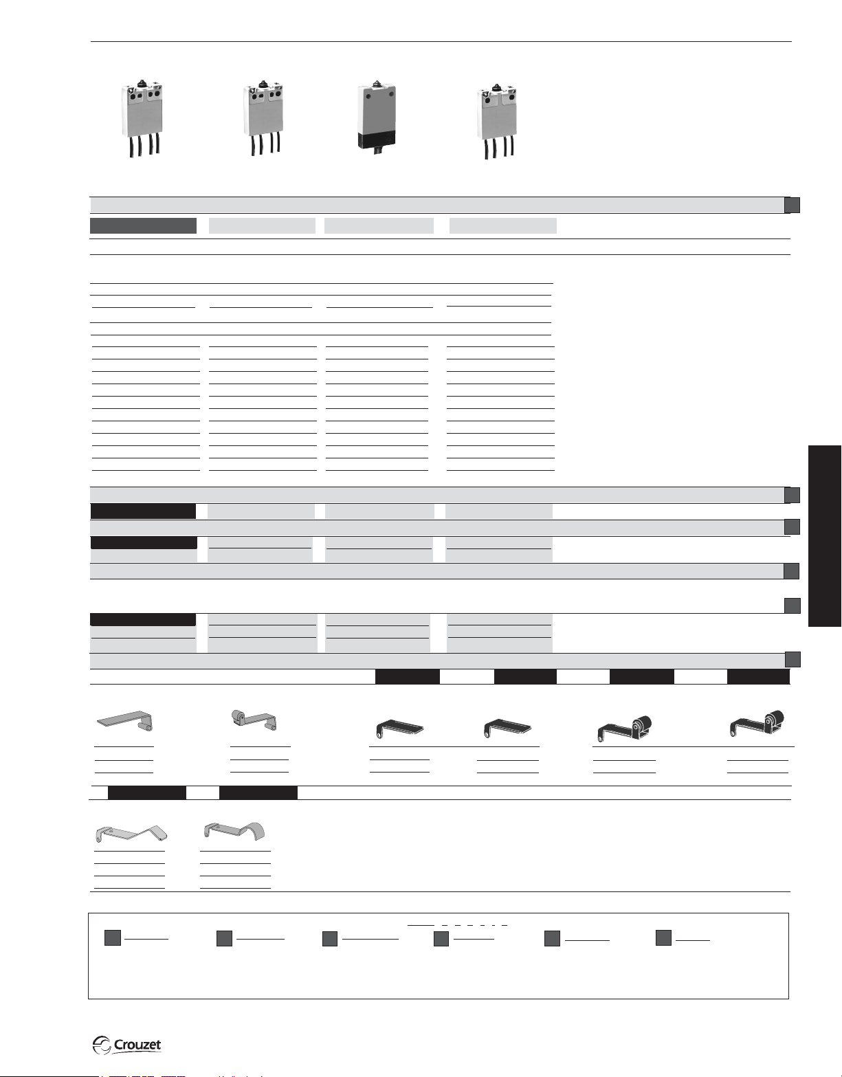
83 139 0
83 139 5
1
83 139 2 83 139 1
Standard
5
3 (10.6)
0.6 (2.1)
4 (14.1)
10 (35.3)
A= 8.8 (.35) B = 9.8 (.39)
+0.4
+.016
+0.4
A:7.7
(.30
) B:8.7
(.32
+.016
0.35±0.1 (.014±.004)
0.3 (.012)
0 to 85 (32 to 185)
7
10
0.3 x 2 (.012 x .008)
37 (1.3)
C
A
B
4 flexible leads ø 2.8 x
2
0.75 mm
length 0.50 m
B
R
L
P
Flat 139 AX R29.7 (1.17)**
Low temperature
5
3 (10.6)
0.6 (2.1)
4 (14.1)
10 (35.3)
A= 8.8 (.35) B = 9.8 (.39)
+0.4
+.016
)
A:7.7
(.30
) B:8.7
+0.4
0.35±0.1 (.014±.004)
0.3 (.012)
0 to 85 (32 to 185)
7
5 x 10
0.3 x 2 (.012 x .008)
37 (1.3)
C
A
B
4 flexible leads ø 2.8 x
2
0.75 mm
length 0.50 m
B
R
L
R
Roller 139 EX R28.7 (1.13)**
Double insulation to NFC
20030 standard classe II
5
3 (10.6)
0.6 (2.1)
4 (14.1)
10 (35.3)
B = 9.8 (.39)
+0.4
+.016
8.7
(.32
)
0.35±0.1 (.014±.004)
0.3 (.012)
-40 to 85 (-40 to 185)
5 x 10
0.3 x 2 (.012 x .008)
45 (1.6)
C
B
3 lead cable 3 x 0.75
mm
B
+.016
(.32
)
6
2
length 0.50 m
A
79 215 740
Explosion proof EEX d
11C T6
5
3 (10.6)
0.6 (2.1)
4 (14.1)
10 (35.3)
B = 9.8 (.39)
+0.4
+.016
+0.4
A:7.7
(.30
) B:8.7
(.32
+.016
)
0.35±0.1 (.014±.004)
0.3 (.012)
-40 to 85 (-40 to 185)
6
5 x 10
0.3 x 2 (.012 x .008)
37 (1.3)
C
B
4 flexible leads ø 2.8 x
2
0.75 mm
length 0.50 m
B
R
L
B E G
79 507 524
79 215 742
R25.4 (1.0)Flat 161A R14.2 (.56) –
2
3
3
4
5
6
70 507 529
R24.1 (.94)Roller 161 E R13.6 (.54) –
1.5 (5.3)
0.2 (.7)
1.5 (.06)
79 218 581
FH
Flat
161F R22.3 (1.17)
2 (7.1)
0.2 (.7)
1.1 (.043)
1.5 (5.3)
0.2 (.7)
1.5 (.06)
79 218 651
Dummy roller 161 G R21.8 (.86)
2 (7.1)
0.2 (.7)
1.1 (.043)
** Factory mounted only
Switch
831390
831391
831392
831395
Type
1
Example switch is: 831390, DBDT, 4 mounting holes, leads exit bottom, .5 meter cable with A actuator. To order actuators seperately, use 8 digit P/N.
Contact Type
2
C
3
Products and specifications subject to change without notice.
2.6 (9.2)
0.35 (1.2)
0.7 (.028)
Note : When mounting actuators, a light greasing of the switch push-button is recommended.
For more actuators, see 83161
1.7 (6)
0.2 (.7)
1.25 (.05)
2.6 (9.2)
0.35 (1.2)
0.7 (.028)
Ø
No Actuator
To order, please specify :
Example : 831390
Mounting Holes
A
B
C A B 5 • A
Connection
4
B
R
L
Lead Length
5
.5 - 1/2 meter (std)
1 - 1 meter
2 - 2 meter
Actuators
6
AF P
BHR
EØ
G
1.7 (6)
0.2 (.7)
1.25 (.047)
3/25
Page 3

Sealed Switches - IP 67
3
1
31
4
2
24
16 (.63)
7 (.28)
Ø2 (.079)
R:1.5 (.06)
R: 1.5 (.06) spherical
2 x Ø3.2 (Ø.125)
2 x Ø2.2 (Ø.087)
5.7
(.22)
25 (.98)
Lead reference
on casing
8.8
(.35)
Tripping Point
24
±0.2
(.94
±.008
)
9
0
-0.2
(.3 5
+0
-.008
)
3
1
31
4
2
24
Ø2 (.079)
R:1.5 (.06)
R: 1.5 (.06) spherical
2 x Ø3.1 (Ø.125)
6.7
(.26)
24 (.94)
Lead reference
on casing
Tripping Point
24
±0.2
(.94
±.008
)
9
0
-0.2
(.35
+0
-.008
)
14
±0.1
(.55
±.004
)
8.7
±0.4
(.314
±.016
)
3
1
31
4
2
24
Ø2 (.079)
R:1.5 (.06)
R: 1.5 (.06) spherical
2 x Ø3.1 (Ø.125)
6.7
(.26)
34 (1.34)
Cable 3 x 0.75 mm2, length 0.5
1 = black lead
2 = brown lead
4 = blue lead
Tripping Point
24
±0.2
(.94
±.008
)
9
0
-0.2
(.35
+0
-.008
)
14
±0.1
(.55
±.004
)
8.7
±0.4
(.314
±.016
)
9.4
(.37)
3.7
(.15)
3
1
31
4
2
24
Ø 4.8x4.8
(Ø .19x.18)
0.5x3.8
(.02x.15)
F
R
9.4
(.37)
4.7
(.185)
3
1
31
4
2
24
0.5x3.8
(.02x.15)
F
R
Dimensions
83 139 0 - 5 - Mounting A = 4 holes
83 139 0 - 1 - 5 - Mounting B = 2 holes
83 139 2
mm (in)
Actuators Factory Mounted Only
Actuators mounting position (type 139)
Lead position - left
Standard lead position
colour black
Lead position - right
Numbering :
1 = black lead
2 = brown lead
3 = grey lead
4 = blue lead
R
Lead position - left
Numbering :
1 = black lead
2 = brown lead
3 = grey lead
4 = blue lead
Standard lead position
colour black
P
Lead position - right
3/26
mm (in)
Products and specifications subject to change without notice.
Page 4

Sealed Switches - IP 67
9
(.35)
3.7
(.15)
3
1
31
4
2
24
4.3
(.17)
0.5x7
(.02x.28)
F
R
4.3
(.17)
0.5x7
(.02x.28)
R 21.8 (.86)
Ø5 (.2)
F
Ø 4.8
(Ø .187)
6.3
(.25)
8
(.3 15)
R
4.3
(.17)
9
(.35)
4.7
(.185)
3
1
31
4
2
24
R: 2.5 (.1)
5
(.2)
F
R
Actuators User or Factory Mounted
Actuators mounting position (type 161)
Lead position - left
Standard lead position
colour black
A- B
H
Lead position - right
E - G
F
3
mm (in)
Products and specifications subject to change without notice.
3/27
 Loading...