

Page 1
›
O110 MV1
A
R
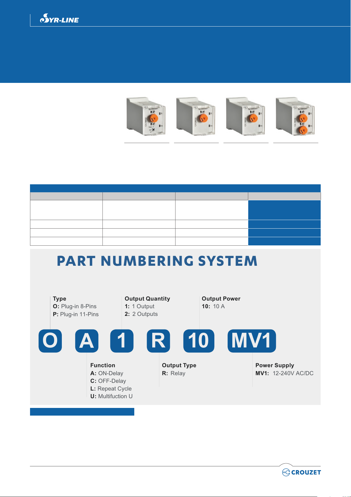
Function
A: ON-Delay
C: OFF-Delay
L: Repeat Cycle
U: Multifuction U
Output Type
R: Relay
Power Supply
MV1: 12-240V AC/DC
Output Quantity
1: 1 Output
2: 2 Outputs
Output Power
10: 10 A
Type
O: Plug-in 8-Pins
P: Plug-in 11-Pins
PART NUMBERING SYSTEM
Plug-In Timer
8 pins
› Multifunction or monofunction
› Compact body for space saving
› Wide time range (from 0.5 seconds to
10 days delay)
› Universal power supply
(12-240 Vz)
› 1 or 2 relay outputs
(SPDT / Changeover)
› Protective cover
› LED status indicator
› 3-wire PNP sensor compatible
› 8-pins connections
Product selection
Function Output Supply Voltage Part Number
Multifuntion U: (A, At, B, C, H, Ht,
D, Di, Ac, Bw)
Ad - N
A 2 relays
C 1 relay
L - Li 1 relay
1 relay
OU1R10MV1
Multifunction U -
Monofunction Ad - N
OA2R10MV1
Monofunction A
12 to 240 Vz
12 to 240 Vz
12 to 240 Vz
12 to 240 Vz
OC1R10MV1
Monofunction C
OU1R10MV1
OA2R10MV1
OC1R10MV1
OL1R10MV1
11/2018
OL1R10MV1
Monofunction L - Li
You have a project? Contact us on www.crouzet.com
Description:
Syr-line, the new specialized range at Crouzet, aimed to satisfy the most unique requirements of your applications by innovating in design,
engineering and development.
The Plug in Analog Timers, a new family of 8 timers with multifuction or monofunction, universal power supply, wide time range, with all the classic
functions.
Page 2
2
11/2018 Plug-In Timer
OU1R10MV1 OA2R10MV1 OC1R10MV1 OL1R10MV1
Power Supply
Rated supply voltage Un
12 to 240 Vz
Voltage supply tolerance -15 %, +10 %
AC supply voltage frequency 50 / 60 Hz ± 5%
Galvanic isolation of supply / inputs No
Power consumption @ Un Approx. 3 VA (VAC) 1.5 W (VDC)
Immunity to power micro cuts 10 ms
Timing Control
Specied time ranges (7) (IEC 1812-1) 0.5..10 s, 0.05..1 min, 0.5..10 min, 0.05.. 1h, 0.5..10 h, 0.05..1 day, 0.5..10 days
Minimum control pulse duration (IEC 1812-1)40 ms
100 ms with load
Recovery time (after by de-energisation)
120 ms
(IEC 1812-1)
Repeatability (IEC 1812-1) ≤ ± 0.5 %
Setting Accuracy (IEC 1812-1) ≤ ± 10 %
Temperature drift ≤ ± 0.05 % / °C
Voltage drift ≤ ± 0.2 % / V
Relay output
Contact arrangement 1 CO (SPDT)
(ChangeOver -Single
Pole Double Throw-)
2 CO (SPDT)
(ChangeOver -Single
Pole Double Throw-)
1 CO (SPDT) (ChangeOver -Single Pole Double
Throw-)
Maximum switching voltage
Switching current rate (resistive) NO / NC:
Minimum switching contact
250 Va/ 10 A resistive / 125 Vc / 0.3 A resistive
NO / NC:
10 A 250 Va / 10 A
30 Vc @ 40 °C
NO / NC:
8 A 250 Va / 8 A
30 Vc @ 60 °C
10 A 250 Va / 10 A
30 Vc @ 25 °C
NO / NC:
5 A 250 Va / 5 A
30 Vc @ 60 °C
10 mA / 5 Vc
NO / NC:
10 A 250 Va / 10 A 30 Vc @ 40 °C
NO / NC:
8 A 250 Va / 8 A 30 Vc @ 60 °C
Maximum switching power (resistive) 2500 VA / 300 W
Electrical life
5
10
cycles min at 250 Va/ 10 A resistive(NO only)
Maximum rate (at max switching power) 360 cycles /hour
6
Mechanical life 10 x 10
cycles
Rated impulse voltage 4 kV (1.2/50 µs)
Dielectric strength between coil / contacts
2.5 kV / 1 min / 1 mA / 50 Hz
(IEC 60664-1)
Dielectric strength between open contacts 1 kV /1 min / 1 mA / 50 Hz
Insulation
Rated Insulation voltage (IEC 60664-1) 250 V
Insulation coordination (IEC 60664-1) Overvoltage category III; pollution degree 2; up to 2 000 m above sea level
Rated impulse voltage (IEC 60664-1) 4 kV (1.2/50µs)
Clearance / Creepage distances (IEC
3 mm / 3.2 mm
60664-1)
Dielectric strength (EN-61812-1) 2.5 kV / 1 min / 1 mA / 50 Hz
Insulation Resistance (NFC 93 050)
> 500 MOhms / 250 Vc / 1 min
General specications
Status indication (LED) Un: green LED blinks when count, ash when waiting Y1, continuous ON when supplied
R: yellow LED blink when only R2 is ON (instantaneous), continuous ON when the 2 relays are ON.
Casing 35 mm
Mounting Mounting base-mounted on socket
Housing material (UL94) Enclosure plastic type V0
Degree of protection (IEC 60529) IP40
Page 3

3
OU1R10MV1 OA2R10MV1 OC1R10MV1 OL1R10MV1
Operating temperature (IEC 60068-2) -20 °C to +60 °C
Storage temperature (IEC 60068-2) -40 °C to +70 °C
Humidity (IEC 60068-2-30) 93 % without condensation
Vibration resistance (IEC 60068-2-6) ± 0.15mm from 10 Hz…60 Hz 2g from 60 Hz..150 Hz
Shock resistance (IEC60068-2-27) 10 gn - 11ms ; 3 x 6 axis (Output non-energized) 5 gn - 1 1ms ; 3 x 6 axis (Output energized)
Drop to concrete oor (IEC 60068-2-32) High: 0.75 m
Weight 90 g
110 g with packaging
Standards
CEE Directive (2014/30/EU
2014/35/EU)
Approvals / Marking CE
Security standard (IEC 60664-1) Insulation coordination for equipment within low-voltage systems
Conformity with environmental directives
(2015/863/UE
1907/2006
2012/19/UE)
Product standard (IEC 61812-1
UL 60947-4-1)
Electromagnetic compatibility (IEC 61000-
6-2
IEC 61000-6-3
IEC 61000-6-4)
Immunity to electrostatic discharges
(IEC61000-4-2)
Immunity to radiated, radio-frequency,
electromagnetic eld (IEC61000-4-3)
Immunity to rapid transient bursts (IEC
61000-4-4)
Immunity to shock waves on power supply
(IEC 61000-4-5)
Immunity to radiofrequency in common
mode (IEC 61000-4-6)
Immunity to voltage dips and breaks (IEC
61000-4-11)
AC/DC main port emissions (IEC 61000-63 IEC 61000-6-4)
Radiated emissions (IEC 61000-6-3 IEC
61000-6-4)
EMC
Low voltage
cULus Listed Industrial Control Equipment
RoHS
Reach
WEEE
Specied time relays for industrial use
Industrial Control Equipment (NRNT- Industrial Control Switches)
Refer to UL840 InsulationCoordinationfor Electrical Equipment
Generic standards
Immunity for industrial environment
Emission residential environment
Emission industrial environment
Level III Air ± 8 KV / Contact ± 6 KV
Level III
10V/m (80 MHz to 1 GHz) 80% AM (1 kHz)
3 V/m (1.4 to 2 GHz) 80% AM (1KHz)
1 V/m (2 to 2.7 GHz) 80% AM (1KHz)
direct ±4kV 5/50 Tr/Th ns 5 KKz & 100KHz
Capacitive coupling clamp ± 2 KV 5/50 Tr/Th ns 5 KHz & 100 KHz
Level III: line-to-earth ±2kV / line-to-line ±1kV
Level III: 10 Vrms (0.15 to 80 MHz) 80 % AM (1 kHz)
0 % residual voltage during 1 cycle (Crit. B)
40 % residual voltage / 10 cycles 50Hz / 12 cycles 60Hz (Crit. C)
70 % residual voltage / 25 cycles 50Hz / 30 cycles 60Hz (Crit. C)
Short interruptions:
0 % residual voltage / 250 cycles 50Hz / 300 cycles 60Hz (Crit. C)
CISPR 16-2-1 (7.4.1), CISPR 16-1-2 (4.3)
0.15 MHz – 0.5 MHz, 66 dB(μV) – 56 dB(μV) quasi-peak, 56 dB(μV) – 46 dB(μV) average
0.5 MHz – 5 MHz, 56 dB(μV) quasi-peak, 46 dB(μV) average
5 MHz – 30 MHz, 60 dB(μV) quasi-peak, 50 dB(μV) average
CISPR 14-1
0.15 MHz – 30 MHz
CISPR 16-2-1 (7.4.1), CISPR 16-1-2 (4.3)
0.15 MHz – 0.5 MHz, 79 dB(μV) quasi-peak, 66 dB(μV) average
0.5 MHz – 30 MHz, 73 dB(μV) quasi-peak, 60 dB(μV) average
CISPR 16-2-3
30 MHz – 230 MHz, 30 dB(μV/m) Quasi-peak at 10 m
230 MHz – 1 000 MHz, 37 dB(μV/m) Quasi-peak at 10 m
Or: 30 MHz – 230 MHz, 40 dB(μV/m) Quasi-peak at 3 m in a semi-anechoic chamber
230 MHz – 1 000 MHz, 47 dB(μV/m) Quasi-peak at 3 m in a semi-anechoic chamber
11/2018 | Plug-In Timer
Page 4

4
OU1R10MV1 OA2R10MV1 OC1R10MV1 OL1R10MV1
Function Diagrams
Basic Time Chart
Function A - On-Delay (Delay on make) Function Ac - On/Off Delay (Delay on make/break)
Function Ad - Delay on Start Function At - Summation time relay
Function B - One-Shot Function Bw
11/2018 Plug-In Timer
Function C - Off-Delay (Delay on break) Function D - Symmetrical ashing (OFF Start)
Function Di - Symmetrical ashing (ON Start) Function H - Interval
Function Ht - Interval summation time relay Function L - Recycler (OFF Start)
Page 5

5
11/2018 | Plug-In Timer
Function Li - Recycler (ON Start) Function N - Watchdog
OU1R10MV1 OA2R10MV1 OC1R10MV1 OL1R10MV1
Connections
OU1R10MV1 - OC1R10MV1
+
U
–
OL1R10MV1
+
–
4
3
R
2
1
U
Y1
5
6
7
8
4
5
Y1
3
R
2
6
7
1
8
OA2R10MV1
+
U
–
R1 R2
3
2
5
4
6
7
1
8
2 6
OU1R10MV1 OA2R10MV1 OC1R10MV1 OL1R10MV1
Outline dimensions (mm)
Socket
RECOMENDED SOCKET
8 Pins for DIN Rail or Panel Mount (P/N: 25 622 130)
35
±0.2
±0.2
45.01
±0.3
7.81
±0.2
53
OU1R10MV1 OA2R10MV1 OC1R10MV1 OL1R10MV1
62.56
±0.3
11.94
±0.2
13.3
±0.2
Warning:
The product information contained in this catalogue is given purely as information and does not constitute a representation, warrantly or any form of contractual commitment. Crouzet Automatismes SAS and its subsidiaries
reserve the right to modify their products without notice. It is imperative that we should be consulted over any particular use or application of our products and it is the responsability of the buyer to establish, particularly through
all the appropriate tests, that the product is suitable for the use or application. Under no circumstances will our warranty apply, nor shall we be held responsible for any application (such as any modication, addition, deletion,
use in conjunction with other electrical or electronic components, circuits or assemblies, or any other unsuitable material or substance) which has not been expressly agreed by us prior to the sale of our products.
 Loading...