

Page 1
| MICROSWITCHES | 1 | WWW.CROUZET-SWITCHES.COM
BASIC TECHNICAL CONCEPTS
INTRODUCTION
Our microswitches are high-precision, snap -action switches and these are the main features for which they are notable:
› Fast and reliable switching largely independent of actuating
speed
› High electrical ratings but small dimensions
› High repeat accuracy of switching points and forces
› Low operating force
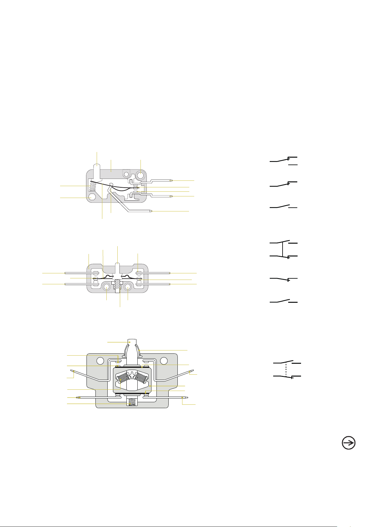
MICROSWITCH CONSTRUCTION - ELECTRICAL FUNCTIONS
› Single-break changeover SPDT Microswitch (e.g. V3 83161)
› Short pre-travel but large overtravel
› Very long service life
› Extensive range of connections, xing means and actuators for
easy adaptation to numerous applications.
| 05/2016
Operating device (Plunger)
Return
spring
Fixing hole
Housing
Conductive pivot point
Snap-acting blade
Fixing hole
NC terminal (2)
Mobile contact
Fixed contact
NO terminal (4)
Common terminal C (1)
› Double-break changeover SPDT Microswitch (e.g. 83132)
Housing
NO terminal (3)
Mobile contact
NC terminal (1)
Fixing hole Fixing hole
NO and NC circuits must be used at same polarity.
Operating device (Plunger)
Snapacting
blade
Return spring
Fixed contact
NO terminal (4)
Mobile c ontact
NC terminal (2)
Changeover SPDT (Form C)
1 (C)
Normally Closed SPST-NC (Form B)
1 (C)
Normally Open SPST-NO (Form A)
1 (C)
Changeover SPDT (Form Za)
3 (NO)
1 (NC) 2 (NC)
Normally closed SPST-NC (Form Y)
1 (NC) 2 (NC)
Normally open SPST-NO (Form X)
3 (NO)
› Double-break changeover SPDT Microswitch with separated circuits (e.g. PBX 8324)
2 (NC)
4 (NO)
2 (NC)
4 (NO)
4 (NO)
4 (NO)
Operating device
(Plunger)
4 xed contacts
4 mobile contacts
NO terminal (13)
Snap-action
springs
NC terminal (21)
Return spring
NO and NC circuits are electrically separated, and can be used at opposite polarities.
Sealing membrane
NO blade
NO terminal (14)
Insulated mobile bracket
NC blade
NC terminal (22)
Changeover SPDT (Form Zb)
13 (N O) 14 (NO)
21 (N C) 22 (NC)
› Positive (or direct) opening operation according to IEC 60947-5-1 Annex K (depending on models)
An additional internal mechanism, made of non-resilient parts,
forces the opening of NC contacts in case of accidental welding
(overload, short-circuit, …) or snap-action mechanism failure.
Models tted with this function are particularly suitable for safety
related applications according to ISO 13849-1 or EN 60204-1.
To ensure proper functioning of positive opening operation, the
operating device must be depressed up to the positive opening position.
› Maintained action / Bistable reset variants
Double-break microswitches (Form Za, X, Y and Zb) are particularly
suitable for achieving this kind of “mechanical memory” function.
Return spring is removed, and operating device has special shape
for push/pull actuation.
Typical applications are level regulation, manual reset and position
contacts for bistable electromagnets.
Page 2
| MICROSWITCHES | 2 | WWW.CROUZET-SWITCHES.COM
MECHANICAL CHARACTERISTICS
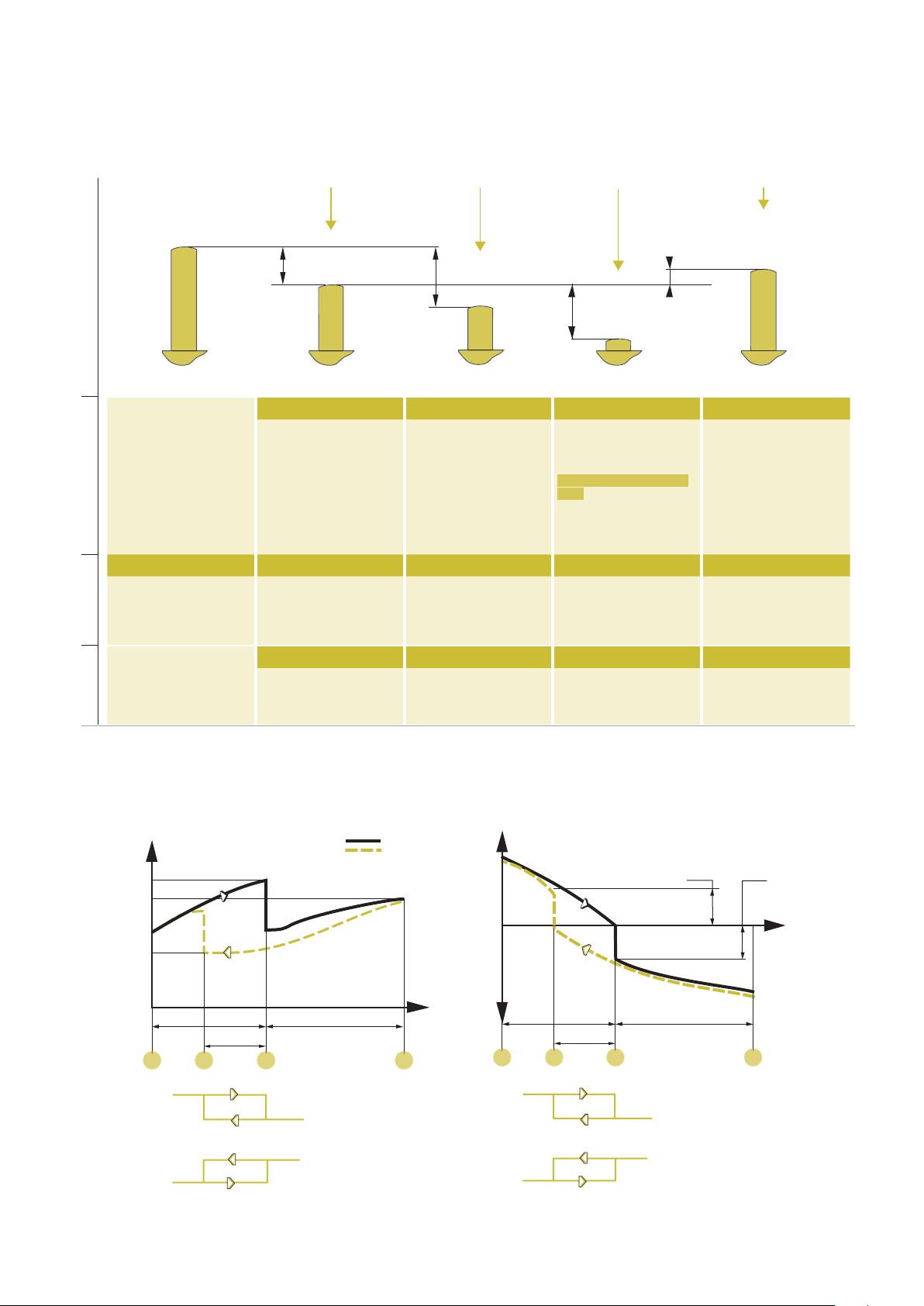
› Terminology: Forces - Positions - Travels
| 05/2016
PT
Actuation of operating device
*Depending on models
RP
OF Operating force
Force required to move
the operating device from
the rest position RP to the
operating position OP
Forces
RP Rest position OP Operating position
Position of the operating
device when no external
mechanical force is applied
Positions
Tra v els
Position of the operating
device at which the snapaction mechanism trips.
PT Pretravel
Distance between the
rest position RP and the
operating position OP
POF*
POT*
POF Positive opening force*
Force to be applied to the
operating device to achieve
the positive opening
operation
POP Positive opening position*
Position of the operating
device where the positive
opening of the NC contacts
is guaranteed
POT Positive opening travel*
Distance between the
rest position RP and the
positive opening position
POP
TTFOF
RF
DT
OT
TTPPOP*OP
TTF Total travel force RF Release force
Force required to reach total
travel position TTP (only
specified when higher than
operating force OF)
AOF Allowable overtravel
force
Maximum force which can
be applied to the operating
device without incurring
deterioration
TTP Total travel position RLP Release position
Position of the operating
device when the applied
force has moved it to the
effective end of the available
travel
OT Overtravel DT Differential travel
Distance between the
operating position OP and
the total travel position TTP
RLP
The level to which the
applied force must be
reduced to allow the snapaction mechanism to return
to its release position RLP
Position of the operating
device at which the snapaction mechanism trips back
to its original position
Distance between the
operating position OP and
the release position RLP
The reference po int for th e figur es given fo r travels an d forces i s a point F located on the top of th e plunger in the case of a plain microsw itch, or, generall y, 3 mm in from th e end of a
flat lever. The refere nce point for the po sitio ns is one of th e fixing h oles, unless oth erwis e indic ated.
› Force - Travel diagrams
On contactsOn operating device
N
OF
TTF
RF
RP RLP OP TTP
NC contact closed
open
NO contact closed
open
PT OT
DT
depression
return
mm
NC contact closed
NO contact closed
N
Force after tripping
return depression
NC
0
NO
PT OT
N
RP RLP OP TTP
DT
open
open
mm
Page 3

➛
➛
➛
➛
NC
NO
< 5 ms
0,3 0,5 12 51016
12
24
48
110
220
| MICROSWITCHES | 3 | WW W.CROUZET-SWITCHES.COM
| 05/2016
ELECTRICAL CHARACTERISTICSMECHANICAL CHARACTERISTICS
› Changeover time
This is the time taken by the mobile contact when moving from
one xed contact to another until it becomes fully stable (contact
bounce included). This time is a function of the contact gap, the
mechanical characteristics of the snap action and the mass of the
mobile element.
However, thanks to the snap-action mechanisms employed, the
time is largely independent of the speed of operation.
It is normally less that 20 milliseconds (including bounce time less
than 5 ms).
Bounce time
< 20 ms
Changeover time
› Actuating speed - Rate of operation
Our microswitches are suitable for actuating speeds varying over
a very wide range: typically from 1 mm/min to 0,5 m/s.
The maximum rate of operation with a low electrical load may be
as high as 10 cycles / second.
› Direct actuation on plunger
The plunger should preferably be actuated
along its axis (front actuation). However,
the majority of our microswitches can
accept lateral approach provided the angle
of actuation is not more than 45°.
› Max rating / Making & Breaking capacities
This is the max current the microswitch is capable of making and
breaking for at least 6000 cycles.
On DC current, the breaking capacity is extremely dependent
on the voltage, the contact gap and the nature of the load being
switched. There is a risk of prolonged or permanent arcing if the
following limits are exceeded:
Vdc
DC breaking capacity can be signicantly increased by using
different means, if necessary in combination:
– Arc reduction device (see «Electrical recommendations»)
– Double-break microswitch
– Microswitch with magnetic blow-out
– Use of several microswitches connected in series and operated
simultaneously
For making and breaking capacities according to utilization
categories AC12, AC13, AC14, AC15 and DC12, DC13,DC14
dened by IEC/EN 60947-5-1: refer to our datasheets.
For special applications, please consult us.
DC max breaking capacities
Resistive load
Inductive load L/R = 5 ms
3 mm contact gap
0.4 mm contact
gap
A
The actuating device shall not limit the
plunger travel to the operating position
(OP). It must always depress the plunger
through at least 0.5 times the dened
overtravel (OT), or up to the positive
must also be taken to ensure that it does not exceed the total
travel position (TTP) nor the allowable overtravel force (AOF).
opening position (POP) if applicable. Steps
› Operation by auxiliary actuator (lever)
When the roller lever is laterally
approached, force should preferably be
applied in the direction shown.
+
Where the movements involved are fast,
the ramp should be designed to ensure
that the operating device is not subjected
to any violent impact or abrupt release.
› Mechanical durability
This is an indicative value of the number
of possible operating cycles without an
electrical load.
It may be useful for evaluation purposes
in cases where the power levels involved
are very low and the electrical life is thus
close to the mechanical life.
› Nominal rating
This is the current the microswitch is capable of making and
breaking, for a given number of cycles (typically 100 000 cycles).
Nominal rating generally corresponds to the highest ampere rating
shown on the operating curve.
› Thermal rating
This is the amount of current the microswitch can withstand when
not being operated; for a terminal temperature rise of not more
than 60°C.
› Electrical durability
Operating curves indicate the electrical life of the microswitches,
under standard conditions (20°C, 1 cycle/2 seconds), by showing
the number of switching cycles that can be performed with varied
types of loads.
Note: for sealed products and/or for DC ratings, the rate of
operation is reduced to 1 cycle/6 seconds.
Example:
Number of
cycles
Resistive circuit
Inductive circuit
400
A
Page 4

c
500 V
µ
| MICROSWITCHES | 4 | WWW.CROUZET-SWITCHES.COM
| 05/2016
› Inuence of load type
Resistive load
This is the reference load that is used for
a resistive load, making and breaking, does not create specic
problem.
Inductive load
τ = L
R
M
In addition, in DC, the phenomenon of contact material relocation
is increased.
Ratings and / or life are reduced and special contacts may be
needed: please contact us.
Also refer to «Electrical recommendations».
Capacitive load and lamps
Breaking these loads is equivalent to that of a resistive load and
does not cause any particular problems.
Ratings and / or life are reduced and special contacts may be
needed: please contact us.
determining the nominal rating. Switching
Electromagnets or motors are typical
examples. They are characterized by a
cos φ <1 in AC or by a time constant
L / R> 0ms in DC.
Breaking these loads creates powerful
arcing that accelerates erosion of
contacts.
Making these loads of ten generates
inrush current up to 6 times the rated
current, which increases the risk of
contact welding.
Making these loads generates inrush
current up to 15 times the rated current,
which greatly increase the risk of contact
welding.
In addition, in DC, the phenomenon of
contact material relocation is strongly
accentuated.
› Contact resistance
This is the electrical resistance measured
at the terminals of the switch when the
contacts are closed. It consists of the
(variable) resistance of the contact point
and the (xed) resistance of the current
carrying parts.
plunger is in rest position or total travel position.
Near the operating or released positions, the contact force
decreases and the resistance may increase substantially.
It is generally less than 20 mΩ, when the
CONTACT MATERIALS
› Choice of contact material
To choose the best material for the contacts there are various
factors to be considered:
– Current and voltage levels
– Type of load
– Potential inrush current
– Number of cycles
– Rate of operation
– Environmental conditions
› Contacts for general use
Our microswitches are normally tted with silver or silver-nickel
contacts. These are suitable for the majority of applications and
provide the best compromise between electrical performance,
thermal performance and service life.
› Contacts for low-energy circuits
For applications at V <20V and/or I <100mA, especially if
P<0.3 VA, we recommend to use contacts with gold (or gold alloy)
coating, especially if the switching frequency is low
(e.g. <1 cycle / week), or in the presence of sulde atmosphere or
other corrosive environments.
The lower limits are not specically dened, but a proper
functioning can usually be assumed down to 4V 1mA. Below this
level, please consult us or refer to «Electrical recommendations».
› Contacts for special applications
We can supply special contacts suitable for various applications,
such as:
– AgSnO2 or AgCdO contacts for very high inrush current
– Gold plated AgNi contacts, possibly with a crossbar
arrangement, to cover a very wide operating range allowing a
single par t number to be used on dif ferent applications (dualcurrent models).
› Insulation resistance
The insulation resistance of our
microswitches is generally greater than
50 000 MΩ measured at 500 V DC.
› Dielectric withstand voltage
The dielectric withstand voltage of our
microswitches is generally higher than
values specied by IEC/EN 61058-1 for
250V rated voltage:
– 1500 volts between live parts and
ground (basic insulation)
– 1500 volts between open contacts for
contact gap >1.5mm (full disconnection)
– 500 volts between open contacts
for contact gap <1.5mm (micro disconnection “µ”)
Page 5

| MICROSWITCHES | 5 | WW W.CROUZET-SWITCHES.COM
| 05/2016
ELECTRICAL RECOMMENDATIONS
› Inductive circuits
To increase the life of contacts and the DC breaking capacity, the
arcing on contact opening can be reduced by using the following
protective circuits:
For DC
For DC or AC
› Very low-energy circuits
Switching very low energy circuits (I<1mA, V<4V) is highly
sensitive to environmental conditions like corrosive atmospheres
and pollutions.
In order to improve the contact reliability, the electrical circuit
should allow the passage of at least a few mA through the
contacts, and at least when the contacts are closing.
Also, the higher the voltage across open contacts, the better the
reliability when the contacts are closed.
Protection by fast diode
VR diode > V supply
IF diode ~ I inductive load
Protection by varistor
V varistor slightly higher than V supply
max
Energy to be dissipated = ½ L I
Protection by RC circuit
R and C values to be adjusted depending
on circuit characteristics
2
› Degree of protection
Degrees of protection provided
by enclosures against access to
hazardous parts, against ingress
of solid foreign objects and against
harmful ingress of water are dened
in IEC 60529 by an IP code followed
by two digits.
1st characteristic numeral
Protection of equipment
against ingress of solid
foreign objects
0 (not protected)
4 diameter ≥ 1 mm
5 dust-protected
6 dust-tight
2nd characteristic numeral
Protection of equipment
against ingress of water with
harmful effects
0 (not protected)
4 splashing
5 jetting
6 powerful jetting
7 temporary immersion
8 continuous immersion
9 high pressure and
temperature water jet
Under this classication, our microswitches mainly come within
the following categories:
– IP40 (with insulated connections): when no indication
– IP65, IP66, IP67, IP69: sealed microswitches, as indicated
Protection of persons
against access to hazardous
parts
(not protected)
1 mm Ø wire
1 mm Ø wire
1 mm Ø wire
INSTALLATION RECOMMENDATIONS
ENVIRONMENTAL CONDITIONS
› Operating temperature
The temperature range covered by our line of
microswitches extends from - 60°C to +250°C.
Operating limits are dened for each type of
microswitch. Within these limits, most of the mechanical
and electrical characteristics are preserved. However,
for cases of intensive use (e.g. numerous thermal cycles
with high electrical load) performance may be reduced.
For more information please contact us.
› Resistance to shock and vibration
Resistance to shock and vibration depends on the mass of the
moving parts and on the forces holding the contacts together. The
criterion of satisfactory performance is the absence of microopening of contacts.
Microswitches without auxiliary actuator
usually exceed the following levels when
plunger is in rest position or total travel
position:
– Vibration (sinusoidal): 10gn, 10 to 500Hz
– Shock: 50gn 11ms half-sine pulse
Further information on request.
› Mounting - Insulation
Our microswitches are built in accordance with the rules of
protection against electric shock dened by IEC/EN 60947-5-1 or
IEC/ EN 610 58-1.
Unless otherwise indicated, they are
intended for Class I devices and their
envelopes provide basic insulation.
Microswitches for Class I equipment are
also suitable for Class II equipment,with
appropriate installation conditions in the
equipment.
Class II microswitches can be used directly in Class II equipment
(and also Class 0, I, and III) without additional protection.
The integrator shall take appropriate measures to ensure
protection against electric shock (clearances and creepage
distances) after installation and connection in the application.
For example:
– An insulating pad may be required between the microswitch and
a conductive mounting surface, or between two microswitches
mounted side by side (optional accessory)
– Actuation of the operating device may require the use of an
intermediate part providing supplementary insulation
– Connections must be protected against direct contact
Please contact us for any additional information related to the
considered microswitch.
Page 6

| MICROSWITCHES | 6 | W WW.CROUZET-SWITCHES.COM
| 05/2016
› Fixing – Tightening torque
Unless otherwise indicated, the tightening torque of the xing
screws must conform to the following values:
Ø of fixing screw mm 2 2.5 3 3.5 4
Tightening torque max. 0.25 0.35 0.6 1 1.5
in N.m min. 0.15 0.25 0.4 0.6 1
› Processing
Silicone containing substances must be excluded from the close
environment of the microswitches because of their negative effect
on the contact resistance.
For the same reason, cyanoacrylate adhesives must be avoided or
carefully selected and tested prior to production run.
Also, grease and oil shall be avoided from the close environment
of the microswitches or shall be evaluated for chemical
compatibility with plastics.
Moreover, grease and oil shall never penetrate inside the
microswitches.
Ultrasonic welding process in the close environment of the
microswitches may affect the contacts and the mechanism.
Therefore, suitable tests and analysis shall be conducted prior to
production run.
Tin soldering must be carried out under an extractor hood in order
to avoid the penetration of solder vapors inside the microswitches,
that may have negative effect on the electric functioning.
STANDARDS, TESTING AND APPROVALS
Our microswitches are designed and tested according to
international standards like:
– EN/IEC 60947-5-1 for general industrial applications
– EN/IEC 61058-1 for household and similar appliances
– EN/IEC 60079 -1 for explosives atmospheres applications.
The Crouzet Switches laborator y is compliant with ISO/IEC 17025
and is cer tied to:
– SMT (Supervised Manufacturer’s Testing) by LCIE, for electrical
tests in accordance with EN/IEC 61058-1
– CTDP (Client Test Data Program) by UL, for electrical tests in
accordance with UL1054/UL61058-1.
Proof of compliance with these standards is demonstrated by:
– The manufacturer’s declaration of conformity (drafted in
accordance with ISO/IEC 17050), or
– Approvals granted by accredited bodies, like LCIE (for ENEC,
NF, ATEX, IECEx approvals), UL (for cURus, cULus approvals),
CQC (for CCC approvals)….
Approval certicates and declarations of conformity can be
obtained from www.crouzet-switches.com
Concerning machinery applications; EN/IEC 62061 and
EN/ISO 13849-1 standards for safety of machinery require the
component manufacturers to provide data allowing the equipment
manufacturers to calculate the Mean Time To Failure (MTTF) and
to determine the Safety Integrity Level (SIL) or the Performance
Level (PL) of the safety related par ts of their control systems.
Reliability data for switches according to EN/ISO13849-1 can be
obtained from www.crouzet-switches.com
Note: with appropriate wiring and monitoring system (like Crouzet
Control safety relays), safety related parts of control systems
containing switches, notably switches with positive opening
operation, can reach PL e / Category 4 according to EN/ISO
13849-1, and SIL 3 according to EN/IEC 62061.
QUALITY
Crouzet Switches undertakes a pro-active quality policy adapted
to our different markets of which the objectives are:
– To actively contribute to the success to our clients
– To ensure the perennial development of the company and
the brand by achieving global performance (social, economic,
product and service offer) in the eld of environment and
legislation.
This quality implies:
– Mobilization and dynamic behavior by the entire staff
– Achieving results and respecting our commitments
– Sharing our policies with our partners (clients, suppliers…).
This quality is based on a series of ongoing actions focusing on
the preventative:
– Quality starts from the understanding of the clients needs in
order to work out the specifications where Crouzet Switches
acts as expert advisor.
– Quality is pro-active in actions for progress
– Quality ensures the systematic exploitation of feedback
experience, methods and quality tools.
Our plants are certified to:
– ISO 9001: quality management systems
– ISO/TS 16949: particular requirements of quality management
systems for automotive production
– ISO/IEC 80079-34: application of quality systems for explosive
atmospheres equipment manufacture
– OHSAS 18 001: occupational health & safety management
systems.
Certicates can be obtained from www.crouzet-switches.com
RULES AND REGULATIONS
› EU directives
Our microswitches conform to:
– Low Voltage directive 2014/35/EU
– ROHS directive 2011/65/EU
– ATEX directive 2014/34/EU
when applicable.
In addition, they can be used within the framework of Machinery
directive 2006/42/EC.
Note about Electromagnetic Compatibility (EMC) directive
2014/30/EU:
– Microswitches, as electromechanical components and as
stated in EN/IEC 60947-1, are not sensitive to electromagnetic
disturbances and their emissions, generated only when
switching, are considered as par t of the normal electromagnetic
environment of low-voltage installations. Therefore, all of our
switches are compliant with the EMC directive.
› Environmental protection
Protection of the environment is an integral part of the
manufacturing process of our microswitches, from design to
packaging.
– ISO 14001: all of our plants are certied.
Certicates can be obtained from www.crouzet-switches.com
– REACH: Crouzet Switches takes into account any change of
the Reach regulation 1907/2006. None of our switches contain
substances from the authorisation list. For performance and
safety purposes, some switches have contacts containing
cadmium oxide which is currently in candidate list.
– WEEE: in order to comply with WEEE 2012/19/EU directive,
Crouzet Switches adheres to an accredited eco-organism.
Switches will come into the scope of WEEE from 2018.
 Loading...