

Page 1
4
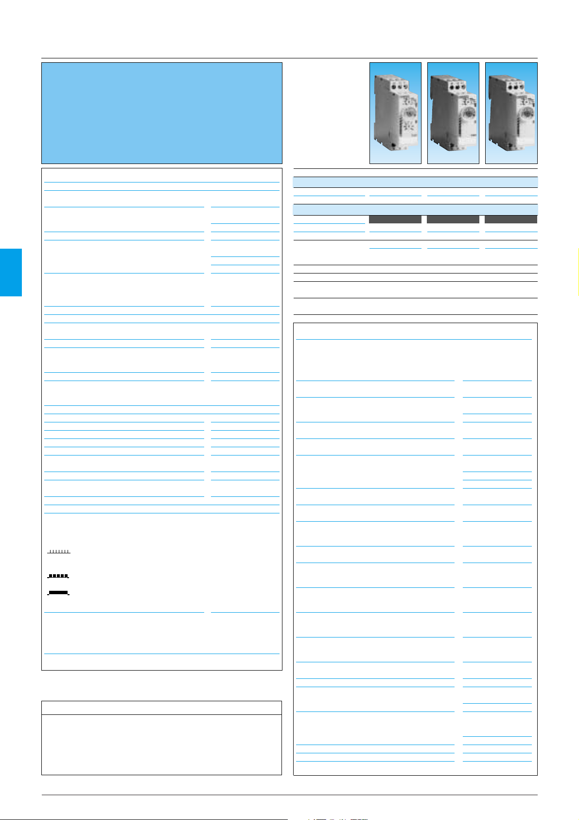
■ Multi-function or mono-function
■ Multi-range (
7 ranges,
available options)
■ Multi-voltage
■ Output 1 relay: 8 A - 250 V (10 A UL)
■ Screw or spring terminals
■ 1 LED status indicators
■ Option of connecting an external power supply to the
control input
■ 3-wire sensor control option
Chronos 2 electronic timers - 22.5 mm
Relay output 1 DTDP relay
Products and specifications subject to change without notice.
Consult factory for application assistance.
204 Airline Drive, Suite 300, Coppell, Texas 75019 / Tel: (800) 677-5311 / FAX: (800) 677-3865 / www.crouzet-usa.com
Technical specifications
Timing
Repetition accuracy (with constant
parameters)
Drift
- Temperature
- Voltage
Display precision according to IEC 1812-1
Minimum pulse duration
- Typically (relay version)
- Typically (solid state version)
- Typically under load (relay version)
Maximum reset time by de-energisation
- Typically (relay version)
- Typically (solid state version)
Immunity to breaks in supply voltage: typically
Power supply
Multi-voltage power supply
Frequency
Operating range
Load factor
Maximum power consumption
Output elements r
1 or 2 changeover relays, AgNi (cadmium-free)
Rated power
Maximum breaking current
Minimum breaking current
Voltage breaking capacity
Electrical life
Mechanical life
Breakdown voltage acc. to IEC 1812-1
Impulse volt
elay output
age acc. to IEC 664-1 IEC 1812-1
Display
State displayed by 2 LEDs
- Flashing green when on
- Relay LED yellow during timing
Green LED operation indicator
Pulsing:
- timer on, no timing in progress
(except functions Di-D and Li-L)
Flashing:
- timing in progress
Permanently lit:
- Relay waiting, no timing in progress
Input type
- Volt-free contact
- 3-wire PNP output control option maximum
residual voltage: 0.4 V whatever the timer
power supply
± 0.5 %
(CEI 1812-1)
± 0.05 % / °C
± 0.2 % / V
±10 % / 25 °C
30 ms
50 ms
100 ms
100 ms
350 ms
>10 ms
depending on version,
see page 1/17
50/60 Hz
85 to 110 % Un
(85 to 120 % Un for
12V AC/DC)
100 %
0.6 W 24V AC/DC
1.5 W 230V AC
32 VA 230V AC
2000 VA / 80 W
2000 V A / 80W
10 AAC 10 A DC
10 mA / 5 VDC
250V AC/VDC
5
10
8 A 250V resistive
5 x 10
2.5 kV / 1min /
1 mA /50Hz
5 kV, wave 1.2 / 50 µs
0.4 V
Other information
Non stocked items, minimum order quantity 100 units.
operations
6
operations
Timing 0.1s • 100h 0.1s • 100h 0.1s • 100h
Types
Screw terminal TUR1 TAR1 TBR1
Spring terminal
- - -
Part numbers and voltage
24V dc / 24 • 240V ac 88 865 105 88 865 115 88 865 125
12 V ac / dc
12 • 240 V ac /d c
- - -
- - -
Functions Multi-function Bifunction Mono-function
A-At - B - C - H-Ht A - At B
Nominal current
Di-D - Ac - Bw
10A 10A 10A
Timing ranges (7 ranges)
0.1s - 1s - 10 s , 6s - 60s , 1 min - 10 min , 6min - 60min , 1 h - 10 h - 100 h
TQR1: Selectable switching time
20 / 40 / 60 / 80 / 100 / 120 / 140 ms
General specifications
Conforming to standards
IEC 1812-1, EN 50081-1/2, EN 50082-1/2, LV
directives (73/23/EEC + 93/68/EEC
(CE marking) + EMC (89/336/EEC +
IEC 669-2-3 (17.5 mm)
Approvals
UL - CSA - cUL listed
Temperatures limits
- use
- stored
Installation category (acc. to IEC 664-1)
Creepage distance and clearance acc. to
IEC 664-1
Degree of protection acc. to IEC 529
- terminal block
- casing
- front face (except Tk2R1)
Vibration resistance acc. to IEC 68-2-6
Relative humidity acc. to IEC 68-2-3
without condensation
Electromagnetic compatibility
- Immunity to electrostatic discharges acc. to
IEC 1000-42
- Immunity to electrostatic fields acc. to
ENV 50140/204 (IEC 1000-4-3)
- Immunity to rapid transient bursts acc. to IEC
1000-4-4
- Immunity to shock waves on power supply
acc. to IEC 1000-4-5
- Immunity to radiofrequency in common mode
acc. to ENV
- Immunity to voltage dips and breaks acc. to
IEC 1000-4-11
- Mains-borne and radiated emissions acc. to
EN 55022 (EN 55011 Group 1)
Fixing: Symmetrical DIN rail (EN 50022)
Connection capacity
- without ferrule
-
with ferrule
Spring terminals, 2 terminals per
connection point
- flexible wire
- rigid wire
Casing material
Weight: 22.5 mm casing
-20 °C + 60 °C
-30 °C + 60 °C
Voltage surge
category
4 kV / 3
IP 20
IP 40
IP 50
f = 10 • 55 Hz
A = 0.35 mm
93 %
Level III
(Air 8 K /
Contact 6 KV)
Level III 10V/m:
80 MHz to 1 GHz)
III (direct 2kV/
Level
Capacitive coupling
clamp 1 KV)
Level III (common
mode 2 KV / residual
current mode 1KV)
Level III (10V rms:
0.15 MHz to 80 MHz)
30 % / 10 ms
60 % / 100 ms >
95 % / 5 s
Class B
35 mm
2
2.5 mm
2 x
2 x
1
.5 mm
2
.5 mm
Self-extinguishing
90 g
1.5 mm
2
2
2
2/34
Page 2
4
U
R
T
T
R
U
Type Part number
Example: Chronos 2 Timers TAR1 88 865 115
21
Standard products
To order, specify:
Function Q
Star-delta
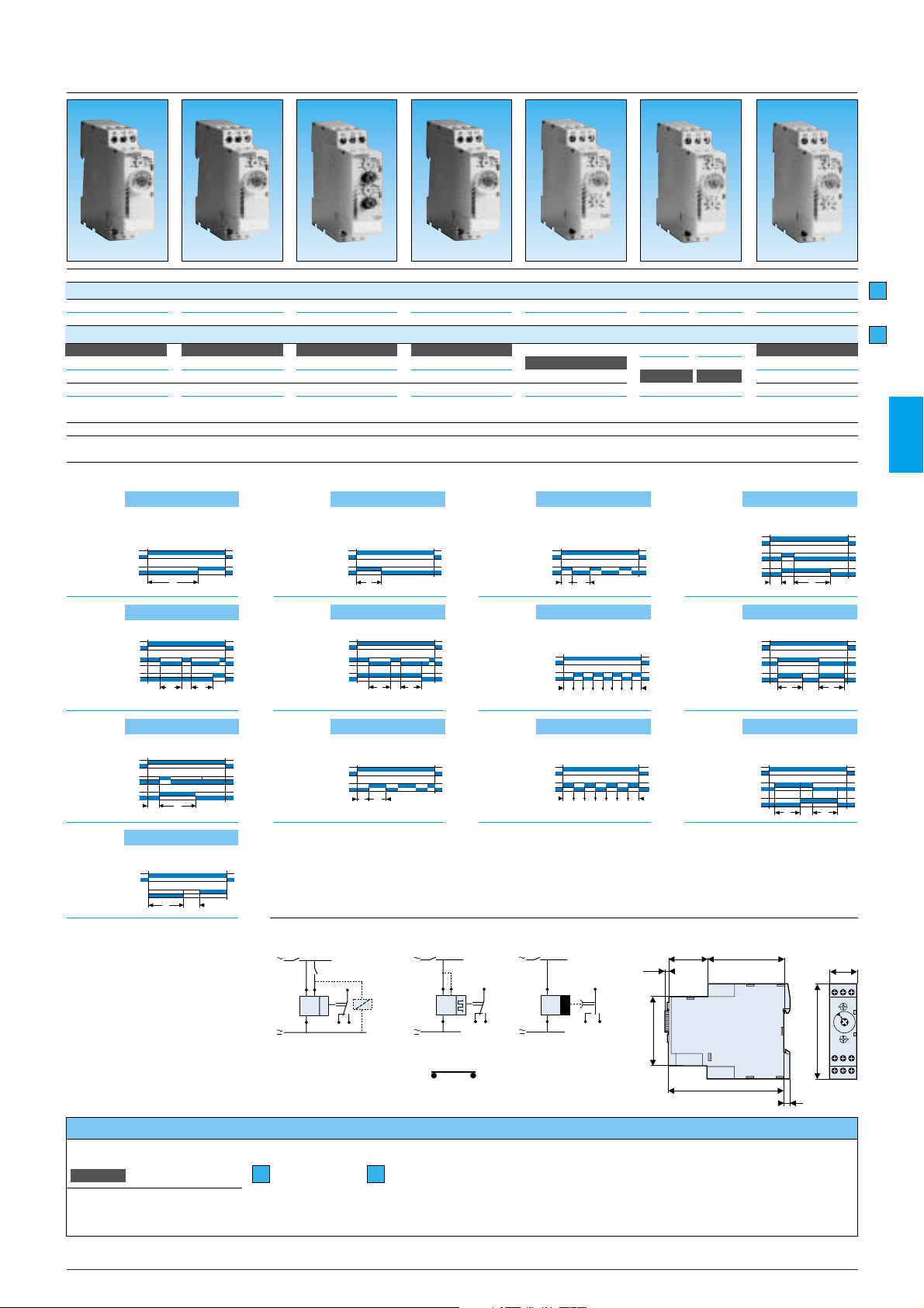
Function diagrams
Connections Y1=C (function diagrams)
Dimensions
32
3,5
95
5
57
78
63
22,5
A1 15 Y1
18 16 A2
Function A
Delay on energisation
1 relay
Function H
Timing on energisation
1 relay
U
C
R
t1 t2
T = t1+t2
Function Ht
Delay on energisation with memory
1 relay
t1
R
C
U
t2
T = t1+t2
Function L
Asymmetrical recycler 1 relay
Pause start
Function D
Flip-flop 1 relay
Pause start
U
TT
R
Function Di
Flip-flop 1 relay
Pulse start
U
R
TT
Function Bw
Pulse output (adjustable)
1 relay
U
C
R
TT
Function Ac
Timing after closing and opening
of control contact
1 relay
U
C
R
TT
A1 Y1
Function At
Timing on energisation with memory
1 relay
Function B
Timing on impulse one shot
1 relay
Function Li
Asymmetrical recycler 1 relay
Pulse start
Function C
Timing after impulse
1 timer
88 865 175
-
Mono-function
Q
10A
-
88 865 100
Multi-function
A-At-B-C-H-HtDi - D - Ac - Bw
10 A
--
--
88 865 103
88 865 503
Multi-function
A-At-B-C-H-HtDi - D - Ac - Bw
10 A
88 865 155
-
Bifunction
Li - L
10 A
88 865 145
-
Bifunction
H - Ht
10 A
88 865 135
-
Mono-function
C
10 A
0.1s • 100h
TCR1
-
0.1s • 100h
THR1
-
0.1s • 100h
TLR1
-
0.1s • 100h
TQR1
-
0.1s • 100h
TUR4
-
88 865 185
-
Multi-function
Ad - Ah - N - O - P Pt - TL - Tt - W
10 A
0.1s • 100h
TXR1
-
0.1s • 100h
TUR3
-
-
TURc3
2
1
MXR1 functions see page 4/i, 4/ii
Functions :
A - At / H - Ht / B / C Li Q
Di - D / Ac / BW L :
Ad - Ah - N - O - P
Pt - T
L - Tt - W
Products and specifications subject to change without notice.
Consult factory for application assistance.
204 Airline Drive, Suite 300, Coppell, Texas 75019 / Tel: (800) 677-5311 / FAX: (800) 677-3865 / www.crouzet-usa.com
U
R
T2
T1
U
C
R
T
U
C
R
T
U
R
T
Ti
U
T1RT2
U
+
A1
15
Y1
R
A2
1816
U
+
15
Y1
A1
R
A2
1516
U
+
A1
A2
15
R
1828
2/35
Page 3

4
■
Multi-function or mono-function
■ Multi-range (
7 ranges,
available options)
■ Multi-voltage
■
Relays output 2: 8 A - 250 V (10 A UL) including
1 instantaneous
■ Screw terminals
■ 1 LED status indicators
■
Option of connecting an external power supply to the
control input
■ 3-wire sensor control option
Chronos 2 electronic timers - 22.5 mm
Relay output 2 DPDT relays
Types
Part numbers and voltage
24V c / 24 • 240V a
12 V a / c
Functions
Nominal current
Timing ranges
(7 ranges)
0.1s - 1s - 10 s , 6s - 60s , 1 min - 10 min , 6min - 60min , 1 h - 10 h - 100 h
TK2R1 (4 ranges)
0.06 s - 0.6 s - 2.5 s - 20 s - 160 s
Timing
± 0.5 %
(CEI 1812-1)
± 0.05 % / °C
± 0.2 % / V
±10 % / 25 °C
30 ms
50 ms
100 ms
100 ms
350 ms
>10 ms
depending on version,
see page 1/13
50/60 Hz
85 to 110 % Un
(85 to 120 % Un for
12V AC/DC)
100 %
0.6 W 24V AC/DC
1.5 W 230V AC
32 VA 230V AC
2000 VA / 80 W
2000 V A / 80W
10 A AC 10 A DC
10 mA / 5 VDC
250V AC/VDC
10
5
operations
8 A 250V resistive
5 x 10
6
operations
2.5 kV / 1min /
1 mA /50Hz
5 kV, wave 1.2 / 50 µs
0.4 V
-20 °C + 60 °C
-30 °C + 60 °C
Voltage surge
category
4 kV / 3
IP 20
IP 40
IP 50
f = 10 • 55 Hz
A = 0.35 mm
93 %
Level III
(Air 8 K /
Contact 6 KV)
Level III 10V/m:
80 MHz to 1 GHz)
Level
III (direct 2kV/
Capacitive coupling
clamp 1 KV)
Level III (common
mode 2 KV / residual
current mode 1KV)
Level III (10V rms:
0.15 MHz to 80 MHz)
30 % / 10 ms
60 % / 100 ms >
95 % / 5 s
Class B
35 mm
2 x
2.5 mm
2
2 x
1.5 mm
2
Self-extinguishing
90 g
General specifications
Conforming to standards
IEC 1812-1, EN 50081-1/2, EN 50082-1/2, LV
directives (73/23/EEC + 93/68/EEC
(CE marking) + EMC (89/336/EEC +
IEC 669-2-3 (17.5 mm)
Approvals
UL - CSA - cUL pending
Temperatures limits
- use
- stored
Installation category (acc. to IEC 664-1)
Creepage distance and clearance acc. to
IEC 664-1
Degree of protection acc. to IEC 529
- terminal block
- casing
- front face (except Tk2R1)
Vibration resistance acc. to IEC 68-2-6
Relative humidity acc. to IEC 68-2-3
without condensation
Electromagnetic compatibility
- Immunity to electrostatic discharges acc. to
IEC 1000-42
- Immunity to electrostatic fields acc. to
ENV 50140/204 (IEC 1000-4-3)
- Immunity to rapid transient bursts acc. to IEC
1000-4-4
- Immunity to shock waves on power supply acc.
to IEC 1000-4-5
- Immunity to radiofrequency in common mode
acc. to ENV
- Immunity to voltage dips and breaks acc. to
IEC 1000-4-11
- Mains-borne and radiated emissions acc. to
EN 55022 (EN 55011 Group 1)
Fixing: Symmetrical DIN rail (EN 50022)
Connection capacity
- without ferrule
-
with ferrule
Casing material
Weight: 22.5 mm casing
Other information
Timing
Repetition accuracy (with constant
parameters)
Drift
- Temperature
- Voltage
Display precision according to IEC 1812-1
Minimum pulse duration
- Typically (relay version)
- Typically (solid state version)
- Typically under load (relay version)
Maximum reset time by de-energisation
- Typically (relay version)
- Typically (solid state version)
Immunity to breaks in supply voltag: typically
Power supply
Multi-voltage power supply
Frequency
Operating range
Load factor
Maximum power consumption
Output elements r
elay output
1 or 2 changeover relays, AgNi (cadmium-free)
Rated power
Maximum breaking current
Minimum breaking current
Voltage breaking capacity
Electrical life
Mechanical life
Breakdown voltage acc. to IEC 1812-1
Impulse volt
age acc. to IEC 664-1 IEC 1812-1
Display
State displayed by 2 LEDs
- Flashing green when on
- Relay LED yellow during timing
Green LED operation indicator
Pulsing:
- timer on, no timing in progress
(except functions Di-D and Li-L)
Flashing:
- timing in progress
Permanently lit:
- Relay waiting, no timing in progress
Input type
- Volt-free contact
- 3-wire PNP output control option maximum
residual voltage: 0.4 V whatever the timer power
supply
Technical specifications
Non stocked items, minimum order quantity 100 units.
Products and specifications subject to change without notice.
Consult factory for application assistance.
204 Airline Drive, Suite 300, Coppell, Texas 75019 / Tel: (800) 677-5311 / FAX: (800) 677-3865 / www.crouzet-usa.com
2/36
Page 4

4
U
A1
A2
R1 R2
15
1816
25
2826
+
U
A1
R1 R2
15
A2
1816
25/21
28/2426/22
Y1
+
Connections Dimensions
32
3,5
95
5
57
78
63
22,5
A1 15 Y1
18 16 A2
Function diagrams
Function A
Delay on energisation
2 timers or
2 relays, including 1 instantaneous
Function C
Timing after impulse
2 timers or
2 relays,
including 1 instantaneous
Function H
Timing on energisation
2 timers or
2 relays,
including 1 instantaneous
Function At
Timing on energisation with memory
2 timers or
2 relays, including 1 instantaneous
U
R1/R2
R2 INST
T
U
C
R1/R2
t1 t2
T = t1+t2
R2 Inst.
Function D
Flip-flop
Pause start
2 timers or
2 relays,
including 1 instantaneous
U
TT
R1/R2
R2 Inst.
Function Di
Flip-flop
Pulse start
2 timers or
2 relays,
including 1 instantaneous
U
R1/R2
TT
R2 Inst.
Function Ac
Timing after closing and opening
of control contact
2 timers or
2 relays,
including 1 instantaneous
Function Bw
Pulse output (adjustable)
2 timers or
2 relays,
including 1 instantaneous
Type Part number
Example: Chronos 2 Timers TA2R1 88 865 215
21
Standard products
To order,specify:
H
Function B
Timing on impulse one shot
2 timers or
2 relays,
including 1 instantaneous
Function K
Delay on de-energisation
True delay OFF
2 relays
Function Ht
Delay on energisation with memory
1 relay
2 timers or
2 relays,
including 1 instantaneous
-
88 865 300
Multi-function
A - At - B - C - H - Ht Di - D - Ac - Bw
8 A
2 timers
including 1
instantaneous
88 865 265
Mono-function
K
8 A
2 timers
88 865 215
Bifunction
A - At
8 A
2 timers
88 865 305
Multi-function
A - At - B - C - H - Ht Di - D - Ac - Bw
8 A
2 timers
including 1
instantaneous
0.1s • 100h
TU2R1
0
.1s • 100h
TA2R1
0
.1s • 100h
TK2R1
0
.1s • 100h
TU2R4
88 865 385
Multi-function
Ad - Ah - N - O - P Pt - TL - Tt - W
8 A
2 timers
including 1
instantaneous
0.1s • 100h
TX2R1
2
1
MXR1 functions see page 1/10, 1/11
Functions :
A - At / H - Ht / B / C K
Di - D / Ac / BW
Ad - Ah - N - O - P
Pt - T
L - Tt - W
Products and specifications subject to change without notice.
Consult factory for application assistance.
204 Airline Drive, Suite 300, Coppell, Texas 75019 / Tel: (800) 677-5311 / FAX: (800) 677-3865 / www.crouzet-usa.com
U
C
R1/R2
R2 inst.
T
∞
R1/R2
R2 Inst.
U
C
TT
U
R1/R2
T
R1/R2
R2 Inst.
U
C
∞ T
R1/R2
R2 Inst.
U
T
U
C
R1/R2
R2 Inst.
t1
t2
T = t1+t2
U
C
R
TT
2/37
Page 5

4
4/i
Function C: Delay on break - timing after impulse
Delay OFF (with constant supply
After energisation, once the control contact is
closed the output state changes.
Timing will only begin on the re-opening of
this control contact (one shot).
Relay R returns to its initial position at the
end of the timing period.
Function D or Di: Repeat cycle - Flip-flop
Repetitive cycle which switches the output
alternately between the rest and operating
position for equal time bases.
T1 + T2 = T total
Function D: the cycle begins with the output
in rest position. Pause start.
Function Di: the cycle begins with the output
in the operating position. Pulse start.
Function H: Timing on energisation
Interval timer - one shot
On energisation, the output changes state,
remains in that state for the duration of timing
and resets at the end of the single cycle.
N.B. This is complementary to function A.
Function B: Single shot - timing on impulse one shot
On pulse (with constant supply)
After energisation; a pulse (≥ 50 ms) or a
maintained control contact will cause the
output to change state which reverts to the
rest position at the end of timing.
N.B. : this process enables shortening or
lengthening of a signal.
Function Bw: Pulse output (adjustable)
AOutput relay R (or the load) changes state,
and remains in the changed-over state for the
timing period, both when control contact C
(Y1) closes and when it opens.
U : Supply C (Y1) : Control contact
R : Output or load relay
T : Timing : indefinite
Function A: Delay on make - delay on energisation
Single timing cycle which begins on
energisation.
The output changes state after timing.
Function Ab: One-shot cycle
The output changes states at the end of the
set time T1, for a period T2.
Both T1 and T2 independently adjustable.
Function Ac: Timing after closing and opening
of control contact
After energisation, closure of the control
contact causes the timing period T to
commence and output relay R (or the load)
changes state at the end of this interval.
When contact C (Y1) opens, relay R resets
after a second timing period T. .
Function Ad :Delay on energisation by switch
(not resettable)
After power-up, pressing or holding down
the switch starts timing. At the end of timing,
the output is energised. The output
will be reset the next time the switch is
pressed or held down.
Function Ah : Flashing single cycle by switch
(not resettable)
After power-up, pressing or holding down
the switch starts timing. At the end of timing,
the output is energised. At the end of this
second timing, the output falls back to
its initial value.
Function At: Timing on energisation with memory
Provides a cumulative time for contact
opening.
The output changes states at the end of the
set time.
Functions
U
C
R1/R2
TT
R2 Inst.
U
C
R
TT
U
C
R1/R2
R2 Inst.
T
T
T
T
R1/R2
R2 INST
1 relay
U
R
U
T
T
2 relays timed or
1 relay timed and 1 instantaneous
U
R
T1 T2
2 relays timed or
1 relay timed and 1 instantaneous
1 relay
U
C
R
TT
1 relay
R1/R2
R2 Inst.
1 relay
U
C
R
U
C
1 relay
U
C
R
U
C
R
TT
TT
2 relays timed or
1 relay timed and 1 instantaneous
2 relays timed or
1 relay timed and 1 instantaneous
2 relays timed or
1 relay timed and 1 instantaneous
1 relay
U
C
R
U
C
R1/R2
R2 inst.
2 relays timed or
1 relay timed and 1 instantaneous
R1/R2
R2 Inst.
1 relay
U
R
U
1 relay
U
R
TT
TT
TT
T
T
T
T
R1/R2
R2 Inst.
2 relays timed or
1 relay timed and 1 instantaneous
1 relay
U
C
R
U
C
t1 t2
T = t1+t2
t1 t2
T = t1+t2
2 relays timed or
1 relay timed and 1 instantaneous
2 relays timed or
1 relay timed and 1 instantaneous
R1/R2
2 Inst.
R1/R2
R2 Inst.
U
1 relay
U
R
U
TT
T
T
Page 6

4
4/ii
Function P : Delayed fixed-length pulse
Timing begins on energisation. At the end of
the timing period output relay R (or the load)
changes state for a period of approx. 500
milliseconds.
Function Pt : Impulse counter (delay on)
Calculates the total opening time of a contact.
At the end of timing, the output is energised
for approximately 500 ms.
Function Q : Star-delta"
At the end of timing, the output is not
energised. It remains "open" (not
conducting) and will only change state
after the fixed time of Ti has elapsed.
Dwell time selectable
Function T : Timing on
energisation with memory
a - energisation by control signal
The timer sums the times for which the
control contact is closed (C1).
Reset is by the reset signal (C2) only.
b - energisation by supply voltage
The timer sums the times for which the
supply voltage (U) is on.
Reset is by the reset signal (C2) only
Function T : Impulse relay
After power-up, pressing or holding down the
switch closes the relay. Pressing the switch a
second time opens the relay.
Function Tt : Timed impulse relay
After power-up, pressing or holding down the
switch closes the relay and starts timing. The
relay opens at the end of timing or when the
switch is pressed a second time.
Function W : Timing after pulse on control contact
After energisation, if the control contact
opens it causes output relay R (or the load)
to change state and timing to start. At the
end of the timing period, relay R resets to its
original state.
Function L : Repeat cylce - Cyclic timing - Asymmetrical recycler
Repetitive cycle comprising 2 independent
adjustable time bases. Each time base
corresponds alternately to a different output
state.
N.B. : The cycle starts with the output in the
rest position.
Function Li : Repeat cylce - Cyclic timing - Asymmetrical recycler
Repetitive cycle comprising 2 independent
adjustable time bases. Each time base
corresponds alternately to a different output
state.
N.B. : The cycle starts with the output in the
operating position.
Function N : "Safe-guard"
At the first control pulse the output is
energised.
To complete the timing the interval between
the two control pulses must be greater than
the timing set.
Function O : "Delayed safe-guard".
On energisation, a first timing sequence
occurs and the output changes state.
With the closing of the control contact, the
output resets and the timing starts, with the
output being activated after timing.
For the timing to be completed, the interval
between the closing of two control contacts
must be greater than the timing set.
1 relay
2 relays timed or
1 relay timed and 1 instantaneous
1 relay
2 relays timed or
1 relay timed and 1 instantaneous
Function Ht : Delay on energisation
with memory
Provides a cumulative time for contact opening.
On energisation, the output changes state,
remains in that state for the duration of timing
and resets at the end of the single cycle.
Function K: Delay on de-energisation - True delay OFF
On energisation, the output changes state.
On de-energisation timing commences and
the output only returns to the reset condition
after timing.
T
R
U
1 relay
2 relays timed or
1 relay timed and 1 instantaneous
1 relay
2 relays timed or
1 relay timed and 1 instantaneous
T
R2
U
R1
R1/R2
R2 Inst.
U
C
R
U
C
t1
t2
T = t1+t2
t1
t2
T = t1+t2
U
R
U
C
R
U
R
TP
P = 500 ms
t1
T= t1+t2
T
t2 P
Ti
U
T1RT2
R1/R2
U
T1
T2
R1/R2
U
R
T1
U
T2
T2
T1
U
C
R
T
U
C
R
U
C
R
8
8
Tt
8
U
C
R
T
TT
U
C
R
T
 Loading...