

Page 1

Page 2

Crouzet Touch Soft User Manual
Table of contents
Crouzet Touch Soft Installation and Startup Guide............................................................... 1-1
1.1. Installation Requirements............................................................................................. 1-1
1.2. Steps to Install Crouzet Touch Soft ............................................................................... 1-2
Utility Manager ..................................................................................................................... 2-1
2.1. Overview ....................................................................................................................... 2-1
2.2. HMI IP, Password .......................................................................................................... 2-3
2.3. Editing Tools .................................................................................................................. 2-4
2.4. Transfer ......................................................................................................................... 2-5
2.5. Simulation ..................................................................................................................... 2-7
2.6. Pass-Through ................................................................................................................ 2-8
Create an Crouzet Touch Soft Project ................................................................................... 3-1
3.1. Overview ....................................................................................................................... 3-1
3.2. Create a New Project File ............................................................................................. 3-1
3.3. Save and Compile the Project File ................................................................................ 3-4
3.4. Run On-Line or Off-Line Simulation .............................................................................. 3-4
3.5. Download the Project File to HMI ................................................................................ 3-5
3.6. Upload the Project File from HMI ............................................................................... 3-10
Hardware Settings ................................................................................................................. 4-1
4.1. Overview ....................................................................................................................... 4-1
4.2. I/O Ports ........................................................................................................................ 4-1
4.3. LED Indicators ............................................................................................................... 4-1
4.4. System Reset ................................................................................................................. 4-2
4.5. System Toolbar .............................................................................................................. 4-3
4.6. EasySystemSetting ........................................................................................................ 4-6
System Parameter Settings ................................................................................................... 5-1
5.1. Overview ....................................................................................................................... 5-1
5.2. Device ........................................................................................................................... 5-1
5.3. Model ............................................................................................................................ 5-9
5.4. General ....................................................................................................................... 5-11
5.5. System Setting ............................................................................................................ 5-13
5.6. Security ....................................................................................................................... 5-16
5.7. Font ............................................................................................................................. 5-19
5.8. Extended Memory ...................................................................................................... 5-20
5.9. Printer / Backup Server ............................................................................................... 5-22
Crouzet Touch Soft
Page 3

Crouzet Touch Soft User Manual
5.10. Time Sync./DST ........................................................................................................... 5-23
5.11. e-Mail .......................................................................................................................... 5-24
5.12. Recipes ........................................................................................................................ 5-27
5.13. Cellular Data Network ................................................................................................ 5-29
Window Operations .............................................................................................................. 6-1
6.1. Overview ....................................................................................................................... 6-1
6.2. Window Types .............................................................................................................. 6-1
6.3. Create, Set, and Delete a Window ................................................................................ 6-3
Event Log ............................................................................................................................... 7-1
7.1. Overview ....................................................................................................................... 7-1
7.2. Event Log Management ................................................................................................ 7-1
7.3. Creating a New Event Log ............................................................................................. 7-4
Data Sampling ....................................................................................................................... 8-1
8.1. Overview ....................................................................................................................... 8-1
8.2. Data Sampling Management ........................................................................................ 8-1
8.3. Creating a New Data Sampling ..................................................................................... 8-1
Object General Properties .................................................................................................... 9-1
9.1. Overview ....................................................................................................................... 9-1
9.2. Selecting PLC and Setting Read/Write Address ............................................................ 9-1
9.3. Using Shape Library and Picture Library ....................................................................... 9-2
9.4. Setting Label Text .......................................................................................................... 9-5
9.5. Adjusting Profile Size .................................................................................................... 9-7
User Password and Object Security .................................................................................... 10-1
10.1. Overview ..................................................................................................................... 10-1
10.2. User Password and Operable Object Classes ............................................................. 10-1
10.3. Enhanced Security Mode and Control Address .......................................................... 10-2
10.4. Enhanced Security Mode Usage ................................................................................. 10-6
10.5. Object Security Settings ............................................................................................ 10-11
10.6. Example of Object Security Settings ......................................................................... 10-13
10.7. Protecting Password Settings from Unauthorized Editing ....................................... 10-16
Index Register ..................................................................................................................... 11-1
11.1. Overview ..................................................................................................................... 11-1
11.2. Examples of Index Register ......................................................................................... 11-2
Keyboard Design and Usage ............................................................................................... 12-1
12.1. Overview ..................................................................................................................... 12-1
12.2. Steps to Design a Popup Keyboard ............................................................................. 12-1
12.3. Steps to Design a Keyboard with Direct Window ....................................................... 12-4
12.4. Steps to Design a Fixed Keyboard on Screen .............................................................. 12-5
Crouzet Touch Soft
Page 4

Crouzet Touch Soft User Manual
12.5. Steps to Design a UNICODE Keyboard ........................................................................ 12-6
Objects ................................................................................................................................ 13-1
13.1. Bit Lamp ...................................................................................................................... 13-1
13.2. Word Lamp ................................................................................................................. 13-3
13.3. Set Bit .......................................................................................................................... 13-7
13.4. Set Word ..................................................................................................................... 13-9
13.5. Function Key ............................................................................................................. 13-17
13.6. Toggle Switch ............................................................................................................ 13-21
13.7. Multi-State Switch .................................................................................................... 13-23
13.8. Slider ......................................................................................................................... 13-26
13.9. Numeric .................................................................................................................... 13-30
13.10. ASCII .......................................................................................................................... 13-44
13.11. Indirect Window ....................................................................................................... 13-47
13.12. Direct Window .......................................................................................................... 13-50
13.13. Moving Shape ........................................................................................................... 13-54
13.14. Animation ................................................................................................................. 13-58
13.15. Bar Graph .................................................................................................................. 13-62
13.16. Meter Display ............................................................................................................ 13-67
13.17. Trend Display ............................................................................................................ 13-72
13.18. History Data Display .................................................................................................. 13-77
13.19. Data Block Display .................................................................................................... 13-83
13.20. XY Plot ....................................................................................................................... 13-91
13.21. Alarm Bar and Alarm Display .................................................................................... 13-97
13.22. Event Display ........................................................................................................... 13-102
13.23. Data Transfer (Trigger-based) ................................................................................. 13-111
13.24. Backup .................................................................................................................... 13-113
13.25. Media Player ........................................................................................................... 13-119
13.26. Data Transfer ........................................................................................................... 13-125
13.27. PLC Control ............................................................................................................. 13-129
13.28. Scheduler ................................................................................................................ 13-136
13.29. Option List ............................................................................................................... 13-145
13.30. Timer ....................................................................................................................... 13-153
13.32. System Message ..................................................................................................... 13-157
13.33. Recipe View ............................................................................................................ 13-159
13.34. Flow Block ............................................................................................................... 13-165
13.35. Operation Log ......................................................................................................... 13-169
13.36. Combo Button......................................................................................................... 13-181
13.37. Circular Trend Display ............................................................................................. 13-184
Crouzet Touch Soft
Page 5

Crouzet Touch Soft User Manual
13.38. Picture View ............................................................................................................ 13-193
13.39. File Browser ............................................................................................................ 13-196
13.40. Import/Export ......................................................................................................... 13-199
13.41. Pie Chart ................................................................................................................. 13-203
13.42. 2D Barcode Display ................................................................................................. 13-205
13.43. String Table ............................................................................................................. 13-207
13.44. Dynamic Scale ......................................................................................................... 13-209
13.45. Dynamic Drawing .................................................................................................... 13-212
13.46. Table ........................................................................................................................ 13-217
13.47. VNC Viewer ............................................................................................................. 13-219
13.48. Contact Editor ......................................................................................................... 13-223
Shape Library and Picture Library ....................................................................................... 14-1
14.1. Overview ..................................................................................................................... 14-1
14.2. Building Shape Library ................................................................................................ 14-1
14.3. Building Picture Library ............................................................................................... 14-8
Label Tag Library and Multi-Language ................................................................................ 15-1
15.1. Overview ..................................................................................................................... 15-1
15.2. Label Tag Library Manager .......................................................................................... 15-1
15.3. Steps to create Label Tag Library ................................................................................ 15-2
15.4. Using Label Tag Library ............................................................................................... 15-3
15.5. Settings of Multi-Language ......................................................................................... 15-4
Address Tag Library ............................................................................................................. 16-1
16.1. Overview ..................................................................................................................... 16-1
16.2. Building Address Tag Library ....................................................................................... 16-1
16.3. Using Address Tag Library ........................................................................................... 16-3
Transferring Recipe Data ..................................................................................................... 17-1
17.1. Overview ..................................................................................................................... 17-1
17.2. Steps to Update Recipe Data with Ethernet or USB Cable ......................................... 17-1
17.3. Steps to Update Recipe Data with SD Card or USB Disk ............................................. 17-2
17.4. Transferring Recipe Data ............................................................................................. 17-3
17.5. Saving Recipe Data Automatically .............................................................................. 17-4
Macro Reference ................................................................................................................. 18-1
18.1. Overview ..................................................................................................................... 18-1
18.2. Instructions to use the Macro Editor .......................................................................... 18-1
18.3. Configuration .............................................................................................................. 18-7
18.4. Syntax .......................................................................................................................... 18-8
18.5. Statement ................................................................................................................. 18-13
18.6. Function Blocks ......................................................................................................... 18-18
Crouzet Touch Soft
Page 6

Crouzet Touch Soft User Manual
18.7. Built-In Function Block .............................................................................................. 18-21
18.8. How to Create and Execute a Macro ........................................................................ 18-81
18.9. User Defined Macro Function................................................................................... 18-86
18.10. Some Notes about Using the Macro ........................................................................ 18-99
18.11. Use the Free Protocol to Control a Device ............................................................. 18-100
18.12. Compiler Error Message ......................................................................................... 18-105
18.13. Sample Macro Code ................................................................................................ 18-110
18.14. Macro TRACE Function ........................................................................................... 18-115
18.15. Example of String Operation Functions .................................................................. 18-119
18.16. Macro Password Protection .................................................................................... 18-127
Configure HMI as a MODBUS Server .................................................................................. 19-1
19.1. Overview ..................................................................................................................... 19-1
19.2. Steps to Create a MODBUS Server ............................................................................. 19-1
19.3. Steps to Access a MODBUS Server ............................................................................. 19-4
19.4. Changing MODBUS Server Station Number Online.................................................... 19-6
19.5. MODBUS Address Type ............................................................................................... 19-6
How to Connect a Barcode Reader ..................................................................................... 20-1
20.1. Overview ..................................................................................................................... 20-1
20.2. Steps to Connect a Barcode Reader ........................................................................... 20-1
Ethernet Communication and Multi-HMI Connection ....................................................... 21-1
21.1. Overview ..................................................................................................................... 21-1
21.2. HMI to HMI Communication ...................................................................................... 21-2
21.3. PC to HMI Communication ......................................................................................... 21-3
System Registers ................................................................................................................. 22-4
22.1. Overview ..................................................................................................................... 22-4
22.2. The Address Ranges of Local HMI .............................................................................. 22-5
22.3. System Registers ......................................................................................................... 22-6
HMI Supported Printers ...................................................................................................... 23-1
23.1. The Supported Printer Types ...................................................................................... 23-1
23.2. Steps to Add a New Printer and Start Printing ........................................................... 23-4
Recipe Editor ....................................................................................................................... 24-1
24.1. Overview ..................................................................................................................... 24-1
24.2. Recipe / Extended Memory Editor Setting ................................................................. 24-1
24.3. Recipe Records Setting ............................................................................................... 24-3
EasyConverter ..................................................................................................................... 25-1
25.1. Overview ..................................................................................................................... 25-1
25.2. Converting Data Log File to Excel File ......................................................................... 25-1
25.3. Converting Event Log File to Excel File ....................................................................... 25-3
Crouzet Touch Soft
Page 7

Crouzet Touch Soft User Manual
25.4. Converting Operation Log File to Excel File ................................................................ 25-4
25.5. Converting Multiple Files ............................................................................................ 25-6
25.6. Scaling Function .......................................................................................................... 25-7
25.7. Batch File .................................................................................................................... 25-8
EasyPrinter .......................................................................................................................... 26-1
26.1. Overview ..................................................................................................................... 26-1
26.2. Using EasyPrinter as a Printer Server ......................................................................... 26-2
26.3. Using EasyPrinter as a Backup Sever .......................................................................... 26-5
26.4. EasyPrinter Operation Guide ...................................................................................... 26-9
26.5. Convert Batch File ..................................................................................................... 26-14
EasySimulator...................................................................................................................... 27-1
27.1. Overview ..................................................................................................................... 27-1
27.2. Steps to setup EasySimulator ..................................................................................... 27-1
Multi-HMI Communication (Master Slave Mode) .............................................................. 28-1
28.1. Overview ..................................................................................................................... 28-1
28.2. Steps to Create a Project of Master HMI .................................................................... 28-1
28.3. Steps to Create a Project of Slave HMI ....................................................................... 28-2
Project Protection ............................................................................................................... 29-1
29.1. Overview ..................................................................................................................... 29-1
29.2. EXOB Password ........................................................................................................... 29-1
29.3. Decompilation is Prohibited ....................................................................................... 29-2
29.4. Disable EXOB Upload Function ................................................................................... 29-3
29.5. Project Key .................................................................................................................. 29-3
29.6. EMTP Password .......................................................................................................... 29-4
Memory Map ...................................................................................................................... 30-1
30.1. Overview ..................................................................................................................... 30-1
30.2. PIN Settings ................................................................................................................. 30-1
30.3. Communication Flowchart ......................................................................................... 30-2
30.4. Address Types ............................................................................................................. 30-3
30.5. Settings ....................................................................................................................... 30-6
FTP Server Application ........................................................................................................ 31-1
31.1. Overview ..................................................................................................................... 31-1
31.2. Steps to Log in FTP Server .......................................................................................... 31-1
31.3. Backup History Data and Update Recipe Data ........................................................... 31-2
EasyDiagnoser ..................................................................................................................... 32-1
32.1. Overview ..................................................................................................................... 32-1
32.2. Configuration .............................................................................................................. 32-1
32.3. EasyDiagnoser Settings ............................................................................................... 32-3
Crouzet Touch Soft
Page 8

Crouzet Touch Soft User Manual
32.4. Error Code ................................................................................................................... 32-9
32.5. Window Adjustment ................................................................................................. 32-10
EasyWatch ........................................................................................................................... 33-1
33.1. Overview ..................................................................................................................... 33-1
33.2. Configuration .............................................................................................................. 33-2
33.3. Monitor Settings ......................................................................................................... 33-3
33.4. Macro Settings ............................................................................................................ 33-8
33.5. HMI Manager .............................................................................................................. 33-9
33.6. Object List ................................................................................................................. 33-11
Administrator Tools ............................................................................................................. 34-1
34.1. Overview ..................................................................................................................... 34-1
34.2. User Accounts ............................................................................................................. 34-2
34.3. USB Security Key ......................................................................................................... 34-6
34.4. e-Mail SMTP Server Settings ...................................................................................... 34-9
34.5. e-Mail Contacts ......................................................................................................... 34-10
EasyDownload ..................................................................................................................... 35-1
35.1. Overview ..................................................................................................................... 35-1
35.2. Configuration .............................................................................................................. 35-1
Data Security ....................................................................................................................... 36-1
36.1. Overview ..................................................................................................................... 36-1
36.2. Configuration .............................................................................................................. 36-1
Crouzet Touch Soft
Page 9

Crouzet Touch Soft Installation and Startup Guide
1-1
Crouzet Touch Soft Installation and Startup Guide
This chapter explains how to install Crouzet Touch Soft.
1.1. Installation Requirements
Software:
Download Crouzet Touch Soft from USB KEY or visit Crouzet website at
http://www.crouzet.com. The language versions include Simplified Chinese, Traditional
Chinese, English, Japanese, German, Italian, Korean, Spanish, Russian, French, and Turkish. The
latest upgraded files can be downloaded too.
Hardware (Recommended):
CPU: INTEL Pentium II or higher
Memory: 256MB or higher
Hard Disk: 2.5GB or higher (Disc space available at least 500MB)
Display: 1024 x 768 resolution or greater
Keyboard and Mouse
Ethernet: for project downloading/uploading
USB Port 2.0: for project downloading/uploading
RS-232 COM: for on-line simulation
Printer
Operating System:
Windows XP / SP3
Windows Vista
Windows 7 (32bit / 64bit)
Windows 8 (32bit / 64bit)
Windows 8.1 (32bit / 64bit)
Windows 10 (32bit / 64bit)
Crouzet Touch Soft
Page 10
Crouzet Touch Soft Installation and Startup Guide
1-2
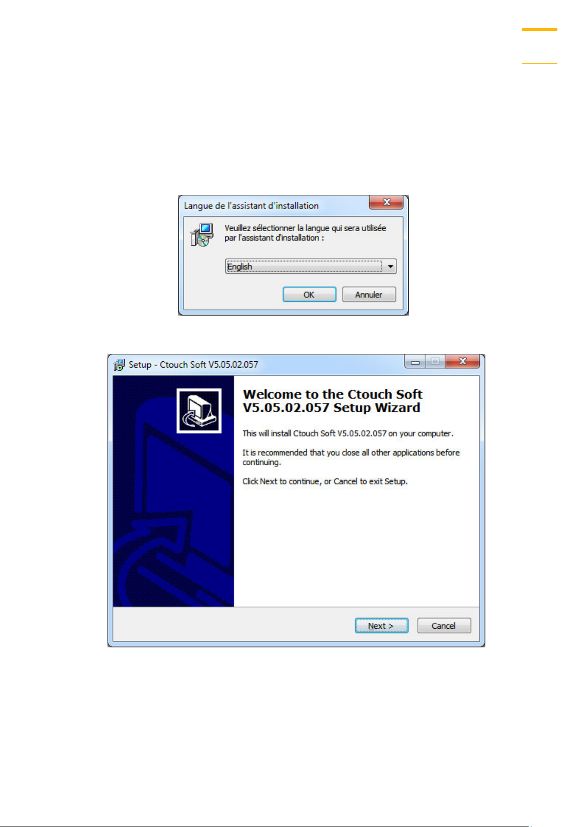
1.2. Steps to Install Crouzet Touch Soft
1. Insert the UB Key your PC. Select the folder “Crouzet Touch Soft Vxx”and run
“Setup_Crouzet_Touch_Soft_Vxx.exe”.
2. The installation screen is shown as the following figure.
3. Click [Install] and select the language for the installation process, and then click [Next].
4. If there is a previous version of Crouzet Touch Soft on the PC, please remove it before
installation.
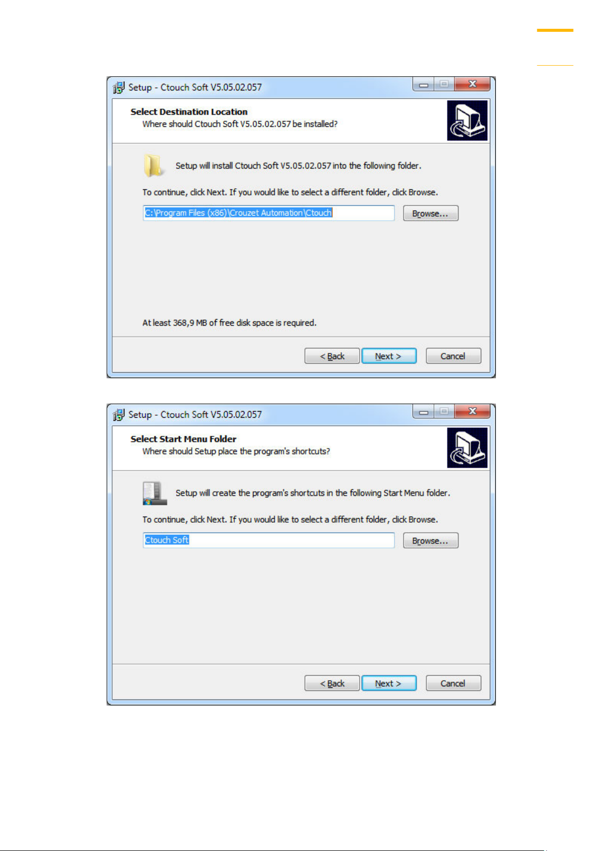
5. Select a folder for Crouzet Touch Soft installation, or use the default folder. Click [Next].
Crouzet Touch Soft
Page 11
Crouzet Touch Soft Installation and Startup Guide
1-3
6. Select a start menu folder, or use the defulat folder. Click [Next].
Crouzet Touch Soft
Page 12
Crouzet Touch Soft Installation and Startup Guide
1-4
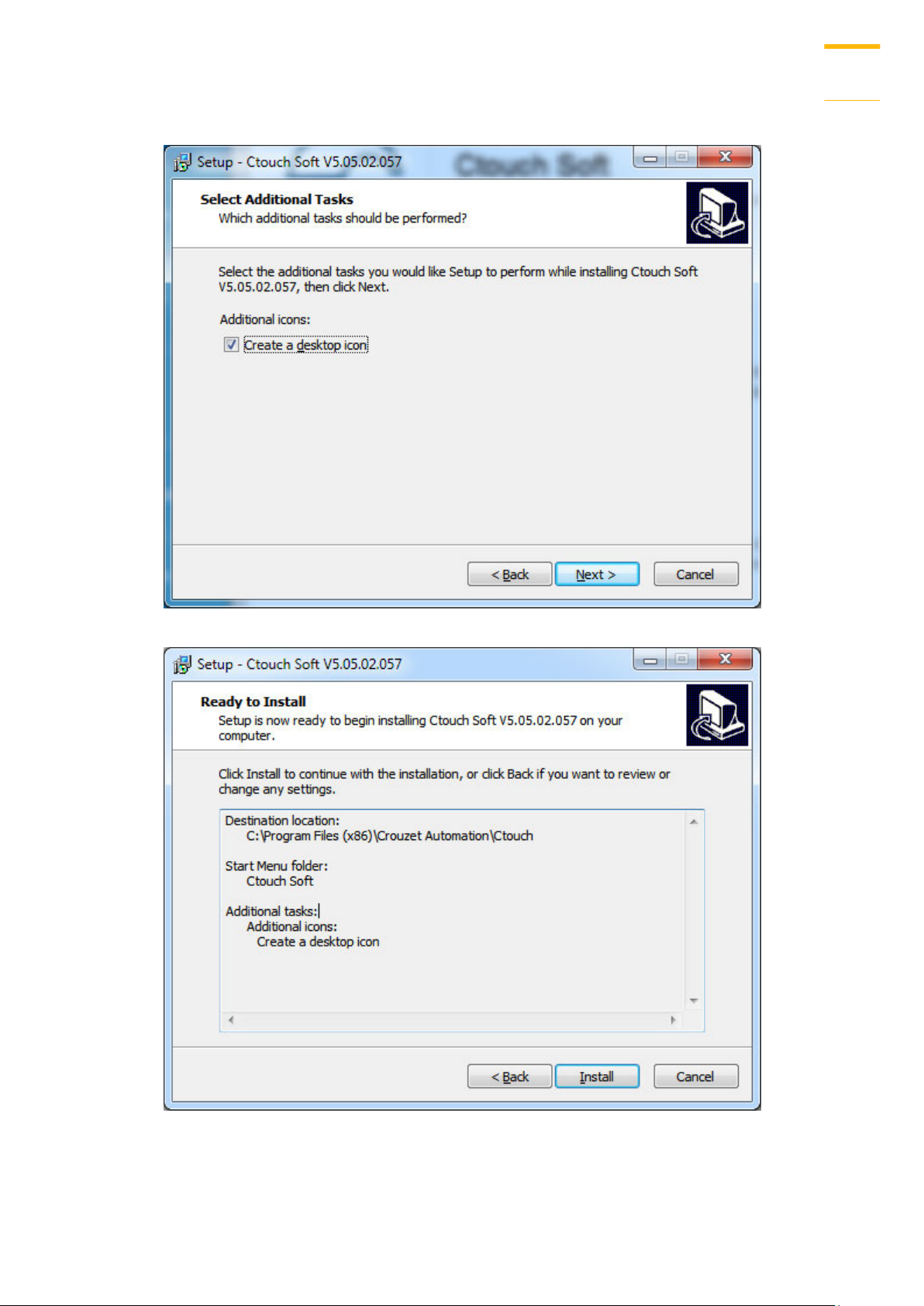
7. Select additional tasks, for example: [Create a desktop icon]. Click [Next].
8. Confirm all setting. To change the setting, click [Back]. To start installation, click [Install].
Crouzet Touch Soft
Page 13
Crouzet Touch Soft Installation and Startup Guide
1-5
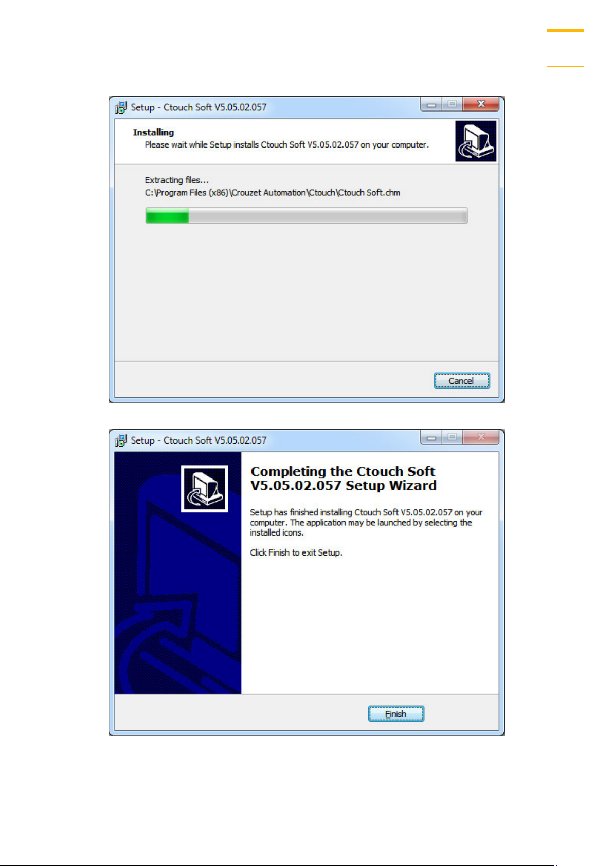
9. Installation progress.
10. Click [Finish] to complete the installation.
Crouzet Touch Soft
Page 14

Crouzet Touch Soft Installation and Startup Guide
1-6
Installed file
Description
Administrator Tools
Saves the data of User Accounts, USB Security Key,
e-Mail SMTP Server Setting, e-Mail Contacts to USB
disk and import to HMI.
Crouzet Touch Soft
Crouzet Touch Soft project editor.
EasyConverter
Conversion tool for Data Sampling and Event Log.
EasyDiagnoser
Monitoring and debugging tool operated on HMI.
EasyPrinter
Remote screen hardcopy and backup server.
EasySimulator
Executes simulation.
EasySystemSetting
Allows updating hardware system settings by using
SD card or USB drive.
EasyWatch
On PC to monitor or set HMI and PLC address value.
Recipe Editor
Tool for setting the format of Recipe data. Users can
open Recipe data or data in the External Memory.
Release Note
Software release notes.
Structure Editor
Supports AB TAG and improve the flexibility to read /
write an object.
Uninstall Crouzet
Touch Soft
Utility Manager
Crouzet Touch Soft management tool.
11. The Crouzet Touch Soft shortcut can be found in [Start] » [All Programs] » [Crouzet Touch
Soft].
The description of each item in Crouzet Touch Soft menu:
Note
HMI supports downloading/uploading projects via USB cable. After installing
Crouzet Touch Soft, the USB driver will be automatically installed. A message saying
“Windows can’t verify the publisher of this driver” may show, please continue anyway.
After installing the USB driver, open [Computer Management] » [Device Manager] to
check if installation succeeded.
Crouzet Touch Soft
Page 15
Utility Manager
2-1
Utilities
Description
Select Model
Select your HMI model. Please note that if the model is incorrect,
certain features may not work correctly.
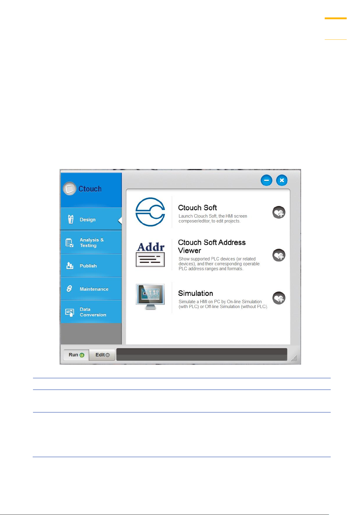
Design
Crouzet Touch Soft: Launch Crouzet Touch Soft to edit projects.
EasyAddressViewer: Review the address ranges and formats of
supported PLCs.
Simulation: Simulate a HMI on PC by On-line Simulation (with
Utility Manager
This chapter explains how to use Utility Manager.
2.1. Overview
After installing Crouzet Touch Soft, double click [UtilityManagerEx] shortcut on the desktop to
start. Utility Manager is for launching several utilities and it is a stand-alone program.
Crouzet Touch Soft
Page 16

Utility Manager
2-2
PLC) or Off-line Simulation (without PLC).
Analysis & Testing
EasyDiagnoser: On-line monitoring and debugging tool. Diagnose
the connection status between PC/HMI and PLC.
See “33 EasyDiagnoser”.
EasyWatch: Allows users to monitor HMI or PLC address values
via Ethernet on PC.
See “35 EasyWatch”.
Reboot HMI: Restart a HMI to its initial condition by Ethernet or
USB connection.
Pass-Through: Allows PC applications to control PLC via HMI. In
this case the HMI is an adaptor.
See “29 Pass-through”.
Publish
Download: Download project file to HMI via Ethernet.
Upload: Upload files on HMI to PC via Ethernet.
Build Download Data for SD/USB Disk:
Build the data to be saved in SD card / USB drive and then insert
the device to HMI to download the data.
Maintenance
EasyPrinter, Backup/Printer Server: A backup/printer server on
PC, which receives backups from HMI and run a defined batch to
convert, or HMI screenshots to print out on PC.
Administrator Tools: Allows storing the data of [User Accounts],
[USB Security Key], [e-Mail SMTP Server Settings], and [e-Mail
Contacts] to USB.
See “36 Administrator Tools”.
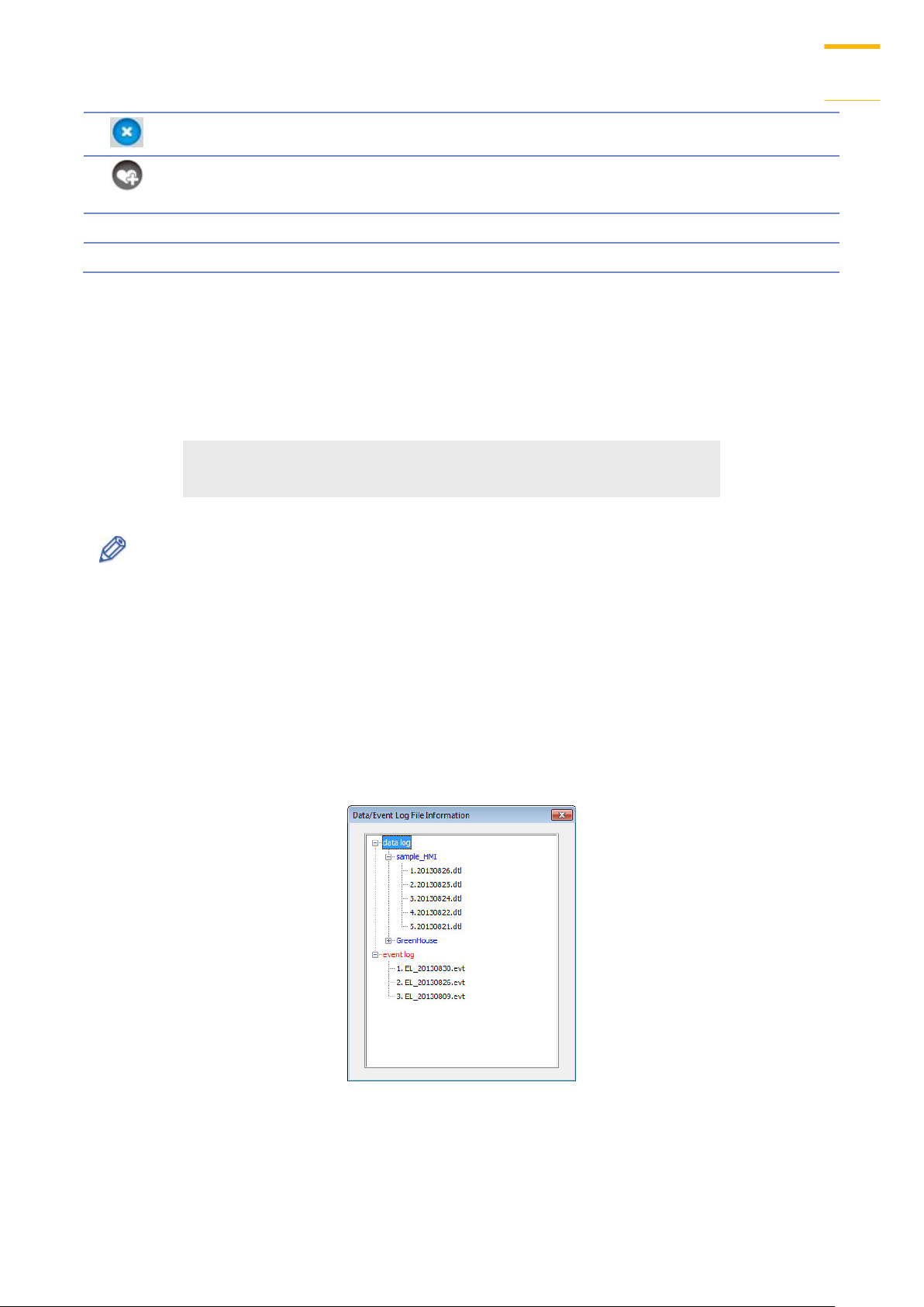
Data/Event log Information: Connect with HMI via USB cable or
Ethernet to check the number of history files in HMI.
Data Conversion
Database Editor: Used to edit recipe data.
Click the icon to download the document about Recipe
Database.
Easy Converter: Reads the data sampling file (.dtl) and event log
file (.evt) in HMI and convert the files to Excel (.xls) format.
See “25 EasyConverter”.
Recipe Editor: Used to create, view, and edit recipe data.
See “24 Recipe Editor”.
Minimize the window.
Crouzet Touch Soft
Page 17
Utility Manager
2-3
Close the window.
Add the frequently used utilities to the toolbar at the bottom of
the window.
Run
Run the selected utility on the toolbar.
Edit
Delete the selected utility on the toolbar.
2.2. HMI IP, Password
Settings
When operating HMI via Ethernet or USB cable, please set the password for HMI to protect
against unauthorized access.
Set the download password. To use masking password, select [Mask] check box.
Note
Please remember the password, otherwise, while restoring HMI default settings, the
project files and data in HMI will be completely erased.
Reboot HMI
Reboot the HMI without unplugging. After reboot, the system returns to the initial state. Set
the correct IP address when rebooting HMI via Ethernet.
Data/Event Log File Information
After setting, connect with HMI to check the number of history files in HMI.
Crouzet Touch Soft
Page 18
Utility Manager
2-4
2.3. Editing Tools
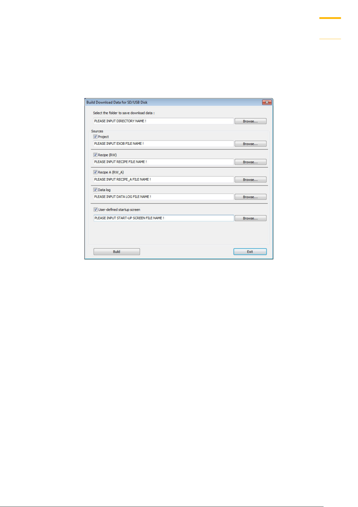
Build Download Data for SD/USB Disk
1. Insert an external device (SD card or USB drive) to PC.
2. Assign the directory to store data.
3. Select the directory of the source file.
4. Click [Build] to create files for downloading.
Files will then be store to the inserted device for users to download to HMI without connecting
via a USB cable or Ethernet.
Steps to Download Project to HMI via USB Disk or SD Card
Assume we will download data in the folder named “123” (K:\123) on an USB disk.
1. Insert USB (in which the project is saved) to HMI.
2. In [Download / Upload] dialog box select [Download].
3. Enter Download Password.
4. In [Download Settings] dialog box, select [Download project files] and [Download history
files] check boxes.
5. Press [OK].
6. In [Pick a Directory] dialog box, select directory: usbdisk\disk_a_1\123.
7. Press [OK].
Project will then be updated.
Crouzet Touch Soft
Page 19
Utility Manager
2-5
Setting
Description
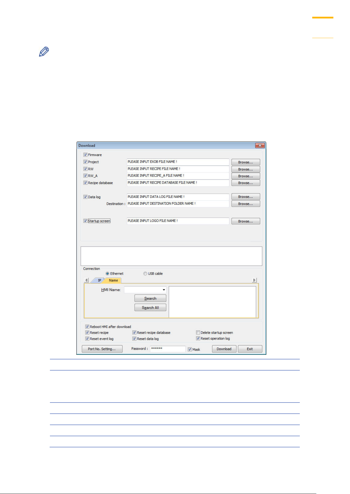
Firmware
Update HMI kernel programs. The firmware
must be downloaded at the first time
downloading data to HMI.
Project
Select an .exob project file.
RW / RW_A
Select a .rcp recipe file.
Recipe database
Select a .db file of Recipe Database.
Data log
Select the data sampling folder in HMI and then
Note
If only the history files are downloaded, it is necessary to reboot HMI to update files.
2.4. Transfer
Download
Download files to HMI via Ethernet or USB cable.
Crouzet Touch Soft
Page 20
Utility Manager
2-6
select a .dtl file.
Startup screen
Download a .bmp bitmap file to HMI. After HMI
is rebooted, this .bmp file will be shown before
project starts.
Reboot HMI after
download
Automatically reboot after download.
Port No. Setting
Select the port by which to download the
project file via Ethernet.
Reset recipe / recipe
database / event log /
data log / operation log
/ Delete startup screen
Erase the selected files in HMI before download.
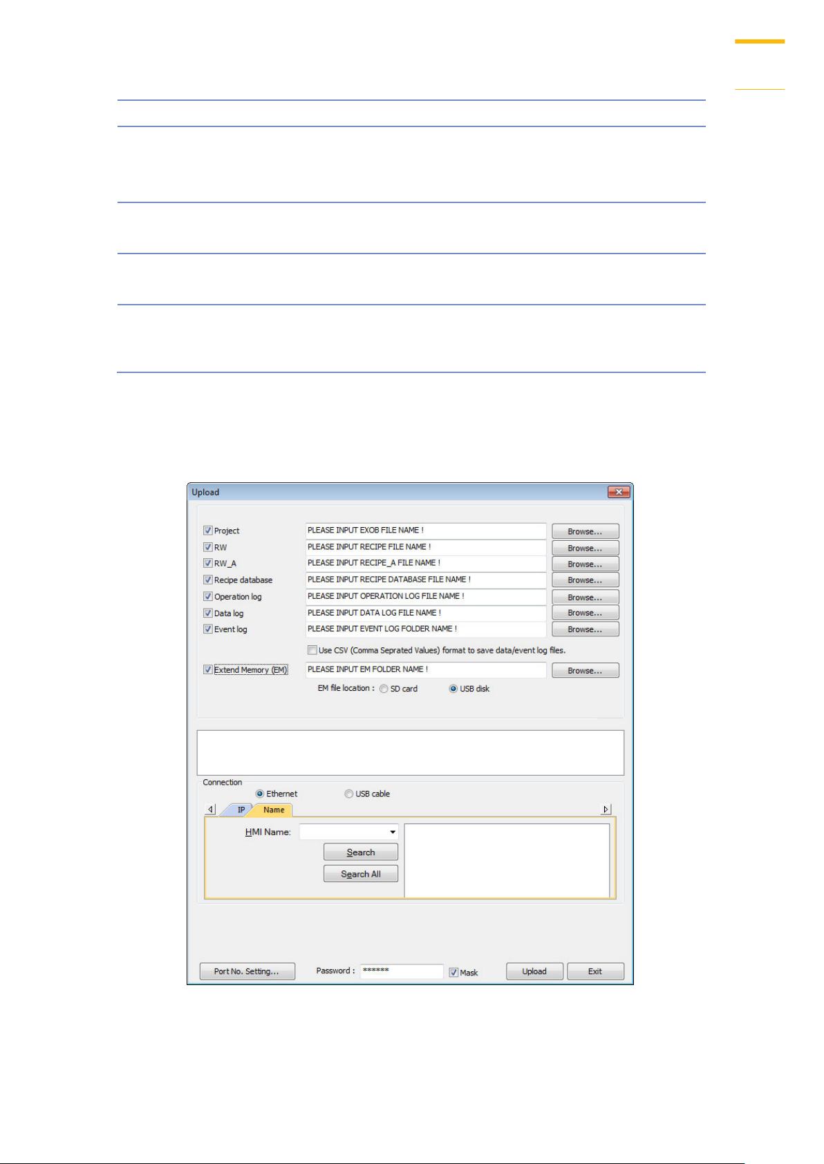
Upload
Upload files from HMI to PC via Ethernet or USB cable. Click [Browse] and assign the file path
before uploading.
Crouzet Touch Soft
Page 21
Utility Manager
2-7
Setting
Description
Event log
Upload the .evt file in HMI to PC.
Extended Memory
(EM)
Upload the .emi file saved in SD card or USB disk
to PC.
Setting
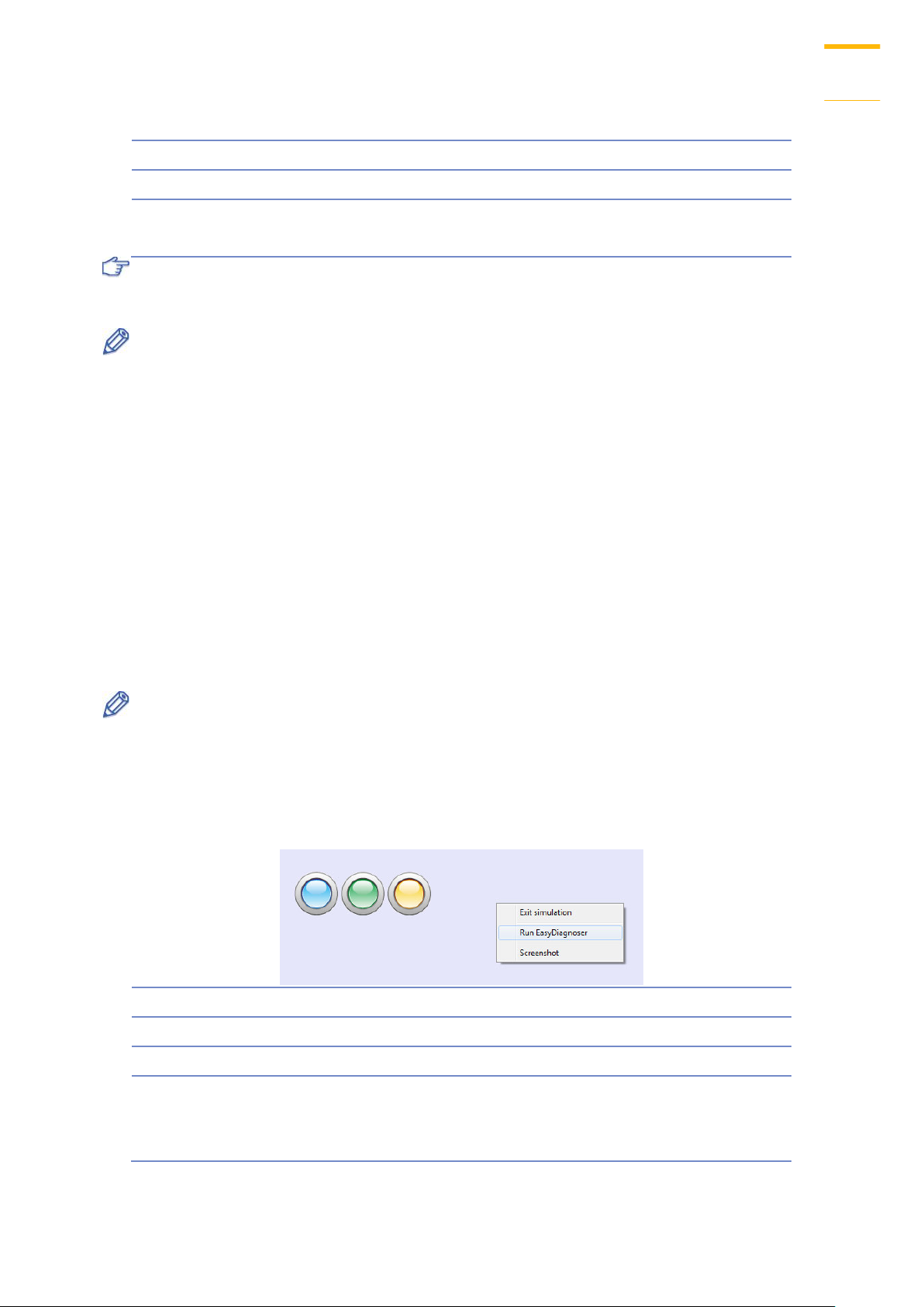
Description
Exit simulation
Stop simulating.
Run EasyDiagnoser
To monitor current communication status.
Screenshot
Capture and save current screen image as a
picture file in the screenshot folder under the
installation directory.
For information about [Project], [RW / RW_A], [Recipe database] or [Data log], see “2.4.1
Download” in this chapter.
Note
The file will be uploaded to PC in .exob format. Please decompile it into editable .emtp file
first and open the .emtp file in Crouzet Touch Soft.
To upload the historical files saved in the external device, please use FTP. See “32 FTP
Server Application” for more information.
2.5. Simulation
Off-line Simulation / On-line Simulation
Off-line simulation: Simulate project operation on PC without any connection.
On-line simulation: Simulate project operation on PC and PLCs are directly connected with PC.
Note
When using [On-line simulation] on PC, if the target device is a local PLC (the PLC directly
connected to PC), there is a 10 minutes simulation limit.
Before executing On-line/Off-line Simulation, please select the source .exob file.
When executing On-line/Off-line Simulation, right click to use these functions:
Crouzet Touch Soft
Page 22
Utility Manager
2-8
2.6. Pass-Through
This function allows the PC application to connect PLC via HMI. In this case, the HMI works like a
converter.
Pass-through provides two modes: [Ethernet] and [COM port].
When using [Ethernet], please install the virtual serial port driver first.
For more detail, please refer to “Chapter 29 Pass-Through Function”.
Crouzet Touch Soft
Page 23
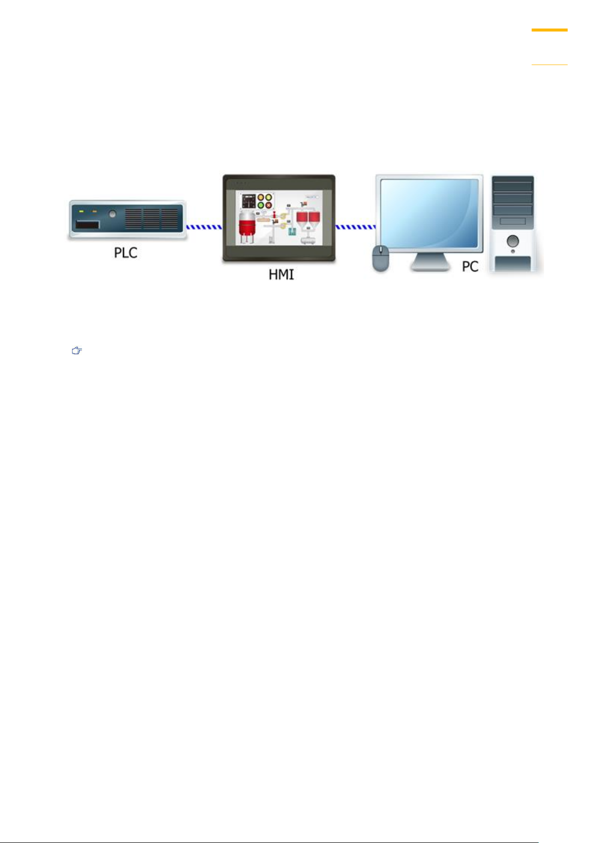
Create an Crouzet Touch Soft Project
3-1
Create an Crouzet Touch Soft Project
This chapter explains the basic steps to create an Crouzet Touch Soft project.
3.1. Overview
The following is the process of creating a project.
1. Create a new project file.
2. Save and compile the project file.
3. Run On-line or Off-line simulation.
4. Download the project file to HMI.
The following describes each process.
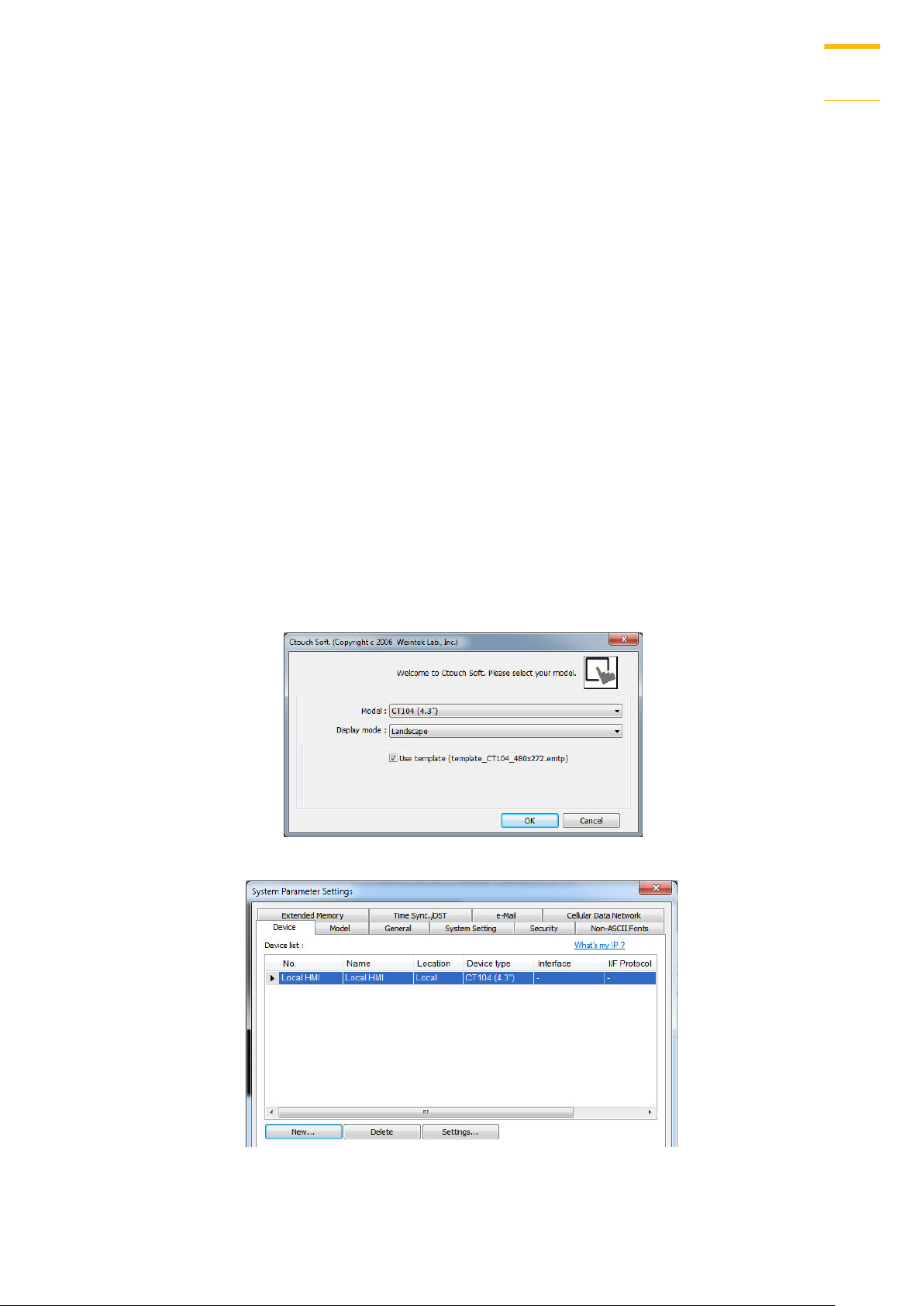
3.2. Create a New Project File
1. Launch Crouzet Touch Soft and open a new file.
2. Select [Model] and select [Use template] check box. Cilck OK
3. Click [New] to add a device.
Crouzet Touch Soft
Page 24
Create an Crouzet Touch Soft Project
3-2
4. Configure parameters.
5. A new device is added to the [Device List].
6. Create an object, take Toggle Switch as an example, and set the address.
Crouzet Touch Soft
Page 25
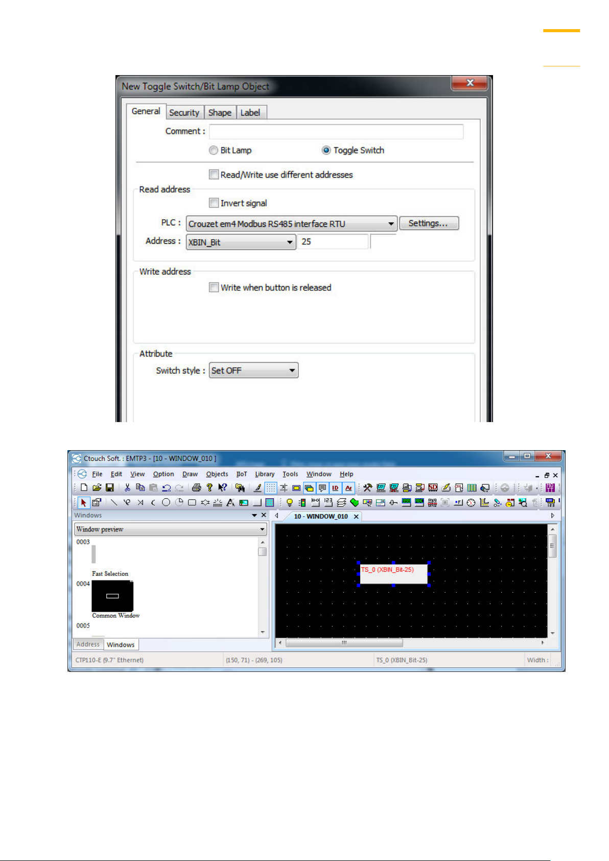
Create an Crouzet Touch Soft Project
3-3
7. Place the object in the edit window. A project is now created.
Crouzet Touch Soft
Page 26
Create an Crouzet Touch Soft Project
3-4
3.3. Save and Compile the Project File
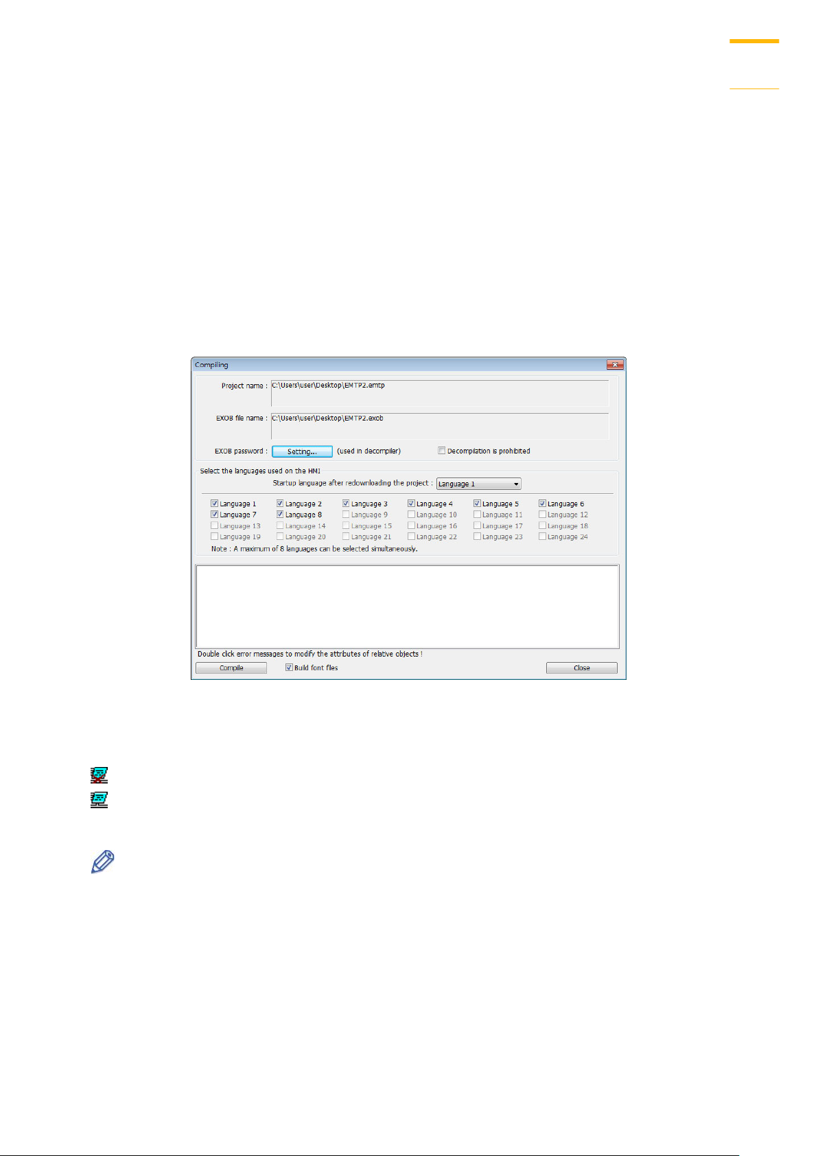
1. In Crouzet Touch Soft toolbar click [File] » [Save] to save the .emtp file.
2. In Crouzet Touch Soft toolbar click [Tools] » [Compile] to compile .emtp file as .exob file,
which could be downloaded to HMI. This also checks if the project can run correctly.
3. To use multiple languages, all languages must be configured in Label Tag Library first.
When downloading the project to HMI, select the needed languages only. A successful
compilation is shown in the following figure.
3.4. Run On-Line or Off-Line Simulation
Off-line simulation: Simulate project operation on PC without connecting any device.
On-line simulation: Simulate project operation on PC without downloading the project to
HMI. The PLC is connected to PC, please set correct parameters.
Note
When using On-line Simulation on PC, if the target device is the PLC directly connected to
PC, there is a 10-minute simulation limit.
Crouzet Touch Soft
Page 27
Create an Crouzet Touch Soft Project
3-5
Setting
Description
Runtime
Select the check box to update the HMI kernel programs.
If this is the first time downloading file or Crouzet Touch
Soft version is updated, please download the firmware
before downloading files to HMI.
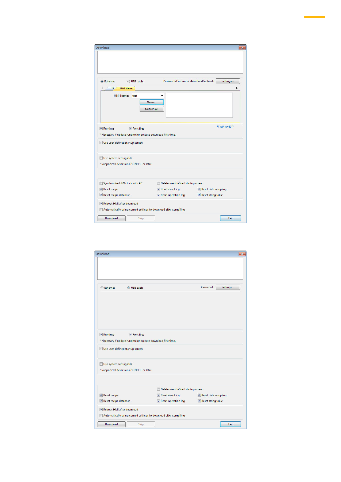
3.5. Download the Project File to HMI
The following explains four ways to download the project file to HMI.
Note
When download project file to HMI using mini USB cable, please do not connect PLC
simultaneously, in order to avoid noise from PLC interfering with HMI.
Configure in Crouzet Touch Soft
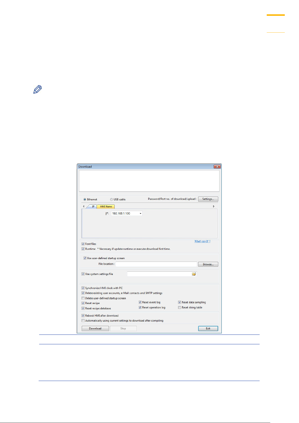
1. In Crouzet Touch Soft toolbar, click [Tools] » [Download]. Make sure that all the settings
are correct.
2. Select [Ethernet], set password and HMI IP.
Crouzet Touch Soft
Page 28

Create an Crouzet Touch Soft Project
3-6
Font files
Download the font used in the project.
Use user-defined
startup screen
Use the picture selected by user as the startup screen.
The picture format must be .bmp.
Use system
settings file
Download the system settings file to update hardware
settings.
Synchronize HMI
clock with PC
Synchronize HMI time with PC time when downloading
project file.
Delete existing
user accounts, eMail contacts
and SMTP
settings
Select the check box to delete existing user accounts, e-
Mail contacts or SMTP settings before downloading the
project. This setting is only effective when one of the
following settings is enabled:
1. [System Parameter Settings] » [Security] » [Enhanced
security mode] » [Use existing user accounts on HMI
first (if existed), Othrewise, use settings below].
2. [System Parameter Settings] » [e-Mail] » [Use existing
user accounts on HMI first (if existed), Othrewise, use
settings below].
Reset recipe/
event log/
data sampling/
recipe database/
operation log/
string table/
user-defined
startup screen
The selected files will be erased before downloading.
Reboot HMI
after download
HMI will reboot after the downloading process is done.
Automatically
using current
settings to
download after
compiling
The system will compile the project and download it to
the latest target HMI. The way to enable this function is
described in the following part.
Note
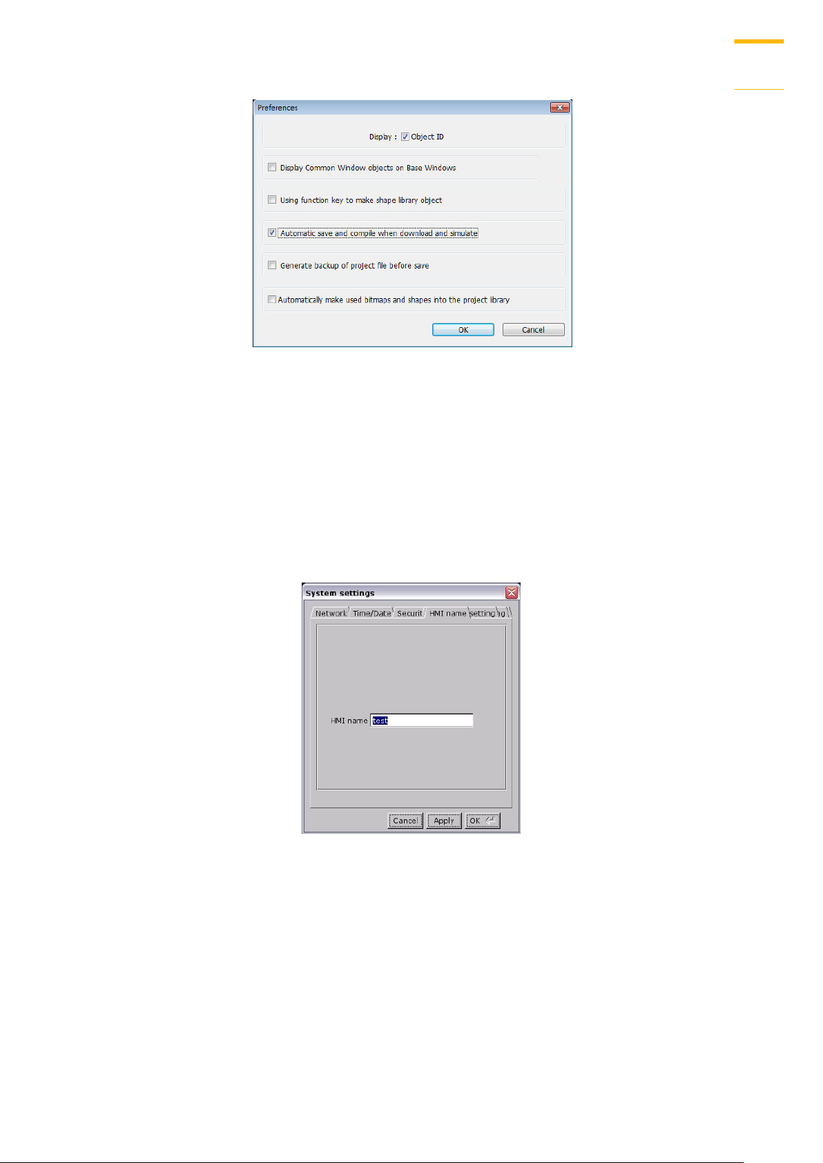
1. In Crouzet Touch Soft toolbar, click [Option] » [Preferences].
2. Select [Automatic save and compile when download and simulate] check box.
Crouzet Touch Soft
Page 29
Create an Crouzet Touch Soft Project
3-7
3. In Crouzet Touch Soft toolbar, click [Save] and then [Download].
4. In the dialog box, select [Automatically using current settings to download after
compiling] check box.
5. Click [Download].
6. When finished, next time when [Download] is clicked, Crouzet Touch Soft will
automatically compile and download the project to the latest target HMI.
Use HMI Name
1. Go to [System settings] on HMI and then set HMI name first.
2. On PC, select the HMI name and start downloading. To use [Search], enter the HMI name
first to search for the HMI. [Search all] searches for all HMIs in the same subnet network.
Crouzet Touch Soft
Page 30
Create an Crouzet Touch Soft Project
3-8
Use USB cable
Crouzet Touch Soft
Page 31

Page 32

Create an Crouzet Touch Soft Project
3-10
5. Select the directory that contains project, and then click [OK] to start downloading.
Note
Please select the parent directory of the generated files when downloading. For the
structure above, please select disk_a_1, not CTP104.
You may click [System Settings] to save the hardware settings configured in Crouzet Touch
Soft into SD card or USB disk, and then download the settings file to HMI. See “4
Hardware Settings” for more information.
3.6. Upload the Project File from HMI
1. On Crouzet Touch Soft toolbar click [Tools] » [Upload].
2. Set HMI IP, HMI model, project location and project name, and then click [Upload].
Crouzet Touch Soft
Page 33

Create an Crouzet Touch Soft Project
3-11
Crouzet Touch Soft
Page 34

Hardware Settings
4-1
LED
Description
PWR (Orange)
Indicates power status.
CPU (Green)
Indicates CPU status. If it blinks or goes out, there may be a CPU
error.
COM
(Blue/Red)
Indicates communication status, blinks during communication.
Hardware Settings
This chapter explains HMI settings.
4.1. Overview
This chapter discusses the HMI settings.
4.2. I/O Ports
The I/O ports are different from one HMI type to another; please see the relevant datasheet
for more information.
The I/O Ports include:
SD card slot: Download / Upload project via SD card, including recipe transfer, event log,
data log…etc and to backup or record history data.
COM Port: Connects PLC or other peripheral devices. The type of serial port include: RS-
232, RS-485 2W, RS-485 4W, and CAN Bus.
Ethernet: Download / Upload project including recipe transfer, event log, data log…etc.
Connects to Ethernet devices, such as PLC, laptop.
USB Host: Supports USB devices, such as mouse, keyboard, USB disk, printer, or barcode
device.
USB Client: Download / Upload project including recipe transfer, event log, and data
log…etc.
For the first time operating HMI, please complete the following system settings. When
finished, the project files designed using Crouzet Touch Soft can be used on HMI.
4.3. LED Indicators
The LED indicators on the HMI indicate:
Crouzet Touch Soft
Page 35

Page 36

Hardware Settings
4-3
Network
When downloading project file to HMI via Ethernet,
set the correct IP of the target HMI. You can obtain
an IP address automatically or enter the IP address
manually. To use Email, please set correct DNS
address.
Time / Date
Set HMI local time/date.
4.5. System Toolbar
After rebooting HMI, you can set the system with [System Toolbar] at the bottom of the screen.
Normally, this bar is hidden automatically. Only by touching the arrow icon at the bottom-right
corner of the screen will the System Toolbar pop up. From left to right the icons are: System
Settings, System Information, Text Keyboard, and Number Keyboard.
How to hide HMI System Setting Toolbar:
When [DIP Switch 2] is set ON, the system setting toolbar is disabled. When set OFF; the
system setting toolbar is enabled. Please restart HMI to enable/disable the toolbar.
System register [LB-9020] can also enable/disable system setting toolbar. When [LB-9020]
is set ON, the toolbar is displayed, and set OFF to hide the toolbar.
System Setting
Set or modify system parameters. Confirm password for security first. The factory default
password is 111111.
Crouzet Touch Soft
Page 37

Hardware Settings
4-4
Security
Password protection, the default is 111111. Please
click the buttons to set the passwords, and finish
password confirmation.
[Password for entering system]
[Password for uploading project]
[Password for downloading project]
[Password for uploading history data]
History
Clears history data in HMI.
HMI name
Set HMI name to be used when download/upload
project.
Firmware setting
[Upgrade OS]
Upgrade firmware. Please do not turn off or unplug
HMI during OS upgrade process. For more details,
see the instruction about OS upgrade of the model
used.
[Portrait Mode]
Set screen orientation mode. After changing the
mode, reconnect HMI to power supply, for the
setting to take effect. That is, disconnect all power
from HMI, and then connect again. If portrait mode
Crouzet Touch Soft
Page 38

Hardware Settings
4-5
is used (90 or 270 degree), the project must be
designed for portrait mode, otherwise it cannot be
correctly displayed.
VNC server
Remote HMI monitoring and controlling via
Ethernet.
[Start VNC single-connection]
Allows connection with one VNC client.
[Start VNC multi-connection]
Allows connection with multiple VNC clients.
Connecting more VNC clients may slow down the
communication speed.
Please see the settings steps in the later part.
Miscellaneous
Rotary switch for adjusting LCD brightness.
[Popup download window]
If selected, after inserting USB disk or SD card to
HMI, the Upload / Download dialog box is displayed.
[Restart after download/upload]
If selected, restarts HMI automatically after
uploading / downloading project.
Misc 2
[Hide mouse cursor]
If selected, the mouse cursor will be hidden.
[Enable [Reset HMI to default] button in calibration
mode]
If selected, when the operator presses and holds
anywhere on the screen for more than 2 seconds
during HMI startup, the touch screen calibration
mode will start. After calibration, [Reset HMI to
default] option shows.
[FTP client can modify USB/SD data]
If selected, USB/SD data can be modified using FTP.
[Modify HMI ports]
Change the port number for Upload/Download and
FTP.
Crouzet Touch Soft
Page 39

Hardware Settings
4-6
Setting
Description
General
[HMI name] Enter HMI name.
[Back light] Adjust LCD backlight brightness.
[Time offset] Set the HMI RTC with offset.
For example, if the current RTC time is 15:00:00, and
System Information
Network: Displays network information & HMI IP.
Version: Displays HMI firmware version and model type.
4.6. EasySystemSetting
EasySystemSetting allows updating hardware system settings by using SD card or USB drive.
The feature is available for HMI OS version 20131106 or later.
Crouzet Touch Soft
Page 40

Hardware Settings
4-7
the time offset is set to -3, the updated time will be
12:00:00.
[Protrait mode] Set the display mode.
Import
Import and edit an existing .conf file.
Export
Export the configured data to a .conf file.
Default
Restore default.
The following explains how to update HMI IP address by using SD card or USB drive.
1. On Crouzet Touch Soft toolbar click [Tools] » [Build Download Data for SD / USB Disk], and
then select [Use system setting] check box.
2. Click [System Settings] button to open [System Setting] Editor dialog box. Specify HMI
network information as shown in the following figure.
3. Click [Export] to generate a “systemsetting.conf” file.
4. Click [Exit] to leave EasySystemSetting.
5. Click [Build] button in [USB Disk/CF Card/SD Card Data] dialog box to generate the file for
download by using SD card or USB disk.
Crouzet Touch Soft
Page 41

Hardware Settings
4-8
6. Insert the storage device that stores the download file to HMI and the Download/Upload
dialog box appears.
7. Press [Load System setting] and then the [Download Config Settings] message appears.
The project file will be updated after finishing system settings.
Crouzet Touch Soft
Page 42

System Parameter Settings
5-1
System Parameter Settings
This chapter introduces the system parameter settings.
5.1. Overview
Launch Crouzet Touch Soft, in the main menu select [Edit] » [System Parameters] to open the
[System Parameter Settings] dialog box. System Parameter Settings are divided into several
tabs as shown in the following figures. These tabs will be introduced respectively in this
chapter.
5.2. Device
Parameters in this tab determine the attributes of each device connected with HMI. The device
can be a Local / Remote HMI / PLC. When creating a new project file, there is a default device
"Local HMI" which indicates the HMI that will be updated and programmed. To change the
relevant device settings, click [System Parameter Settings] » [Settings] to open [Device
Properties] dialog box.
How to Control a Local PLC
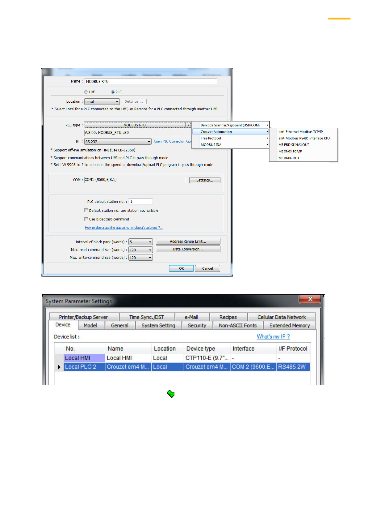
“Local PLC” means the PLC is connected to the local HMI. To control/connect a Local PLC, add
this type of device first. Click [System Parameter Settings] » [New] to open [Device Properties]
dialog box. For example, when connecting MODBUS RTU as a Local PLC:
Crouzet Touch Soft
Page 43

System Parameter Settings
5-2
Setting
Description
Name
The name of the device.
HMI / PLC
In this example the device used is a PLC, so select [PLC].
Location
Select [Local] or [Remote]. In this example the PLC is
connected to the Local HMI, so select [Local].
PLC type
Select the type of the PLC.
PLC I/F
The available PLC interface: [RS-232], [RS-485 2W], [RS-485
4W], [Ethernet], [USB], and [CAN Bus].
If the interface used is [RS-232], [RS-485 2W], or [RS-
485 4W], configure communication parameters by
clicking [Device Properties] » [Settings] and then
[Com Port Settings] dialog box opens.
Timeout
If the communication has been disconnected for more
Crouzet Touch Soft
Page 44

System Parameter Settings
5-3
than preset time limit configured in [Timeout] (in sec),
Window No. 5 will pop up and show “PLC No Response”
message.
Turn around delay
While sending the next command to PLC, HMI will delay
the sending according to the time interval set in [Turn
around delay]. This may influence the efficiency of the
communication between HMI and PLC. Default value is
“0”.
If the interface used is [Ethernet], click [Device
Properties] » [Settings] and the [IP Address Settings]
dialog box opens. Please set correct PLC IP address
and port number.
If the interface is [USB], no further setting is
required. Please check the settings in [Device
Properties].
If the interface is [CAN (Controller Area Network)
Bus], please see “PLC Connect Guide” for “CANopen”
and import the .eds device file.
PLC default
station no.
The default station number for PLC address if the PLC
station number is not included in the address. PLC station
no. can be set in PLC address. The address format:
ABC#DEFGH
ABC stands for PLC station number and ranges from 0 to
255. DEFGH stands for PLC address. And the “#” sign
separates the station number and the address. As shown
in the following figure, the data is read from PLC station
number 1, and address 0x-20.
Crouzet Touch Soft
Page 45

System Parameter Settings
5-4
Default
station no.
use station
no. variable
Use the station number variables as the default PLC
station number. Select one from LW-10000 to LW-10015
(var0 to var15) as the station number variables. If the
station no. is not specified in PLC address, the station
number will be determined by the station no. variable.
For example, if var3 is set for default station no:
The followings demonstrate some examples:
The PLC station number is “5”.
The PLC station number is determined by var7 (LW-
10007)
PLC address is set to “111”, since PLC station no. is
not specified, and the default station no. is var3, the
PLC station no. is determined by var3 (LW-10003).
Use
broadcast
When [Use broadcast command] check box is selected,
please fill in [Broadcast station no.] according to the
Crouzet Touch Soft
Page 46

System Parameter Settings
5-5
command
broadcast station number defined by PLC. When HMI
sends a broadcast command to the station number set
here, PLC will only receive the command and not reply to
HMI.
As shown in the following figure:
When HMI sends a command to address 255#200, all the
PLCs will receive this command and will not reply.
Only PLCs that support broadcast command can use this
feature.
Interval of
block pack
(words)
If the interval between read addresses of different
commands is less than this value, the commands can be
combined to one. The combining function is disabled if
this value is set to “0”.
For example, the interval value is set to “5”, to read 1 word
from LW-3 and 2 words from LW-6 respectively (read from
LW-6 to LW-7), since the interval of addresses between
LW-3 and LW-6 is less than 5, these two commands can be
combined to one. The result is to read 5 consecutive words
from LW-3 to LW-7.
Note: The maximum size of command combination data
must be less than [Max. read-command size].
Max. read -
command
size (words)
The maximum data size to read from the device at one
time. Unit: word
Max. write command
size (words)
The maximum data size to write to the device at one time.
Unit: word.
After all settings are completed, a new device named “Local PLC 1” is added to the [Device list].
Crouzet Touch Soft
Page 47

System Parameter Settings
5-6
Setting
Description
HMI or PLC
In this example, the device used is a PLC, so select [PLC].
Location
Select [Local] or [Remote]. In this example the PLC is
connected to Remote HMI, so select [Remote]. Set the IP
address and port number of the Remote HMI by clicking
[Settings] next to [Remote].
How to Control a Remote PLC
“Remote PLC” is a PLC being connected to a remote HMI. To control a remote PLC, add this
type of device first. Please click [System Parameter Settings] » [New] to open [Device
Properties] dialog box. For example, use MODBUS RTU as the Remote PLC:
Crouzet Touch Soft
Page 48

System Parameter Settings
5-7
PLC Type
Select the type of the PLC.
PLC I/F
The interface used for Remote PLC. If the remote PLC uses a
COM port, select [RS-232], [RS-485 2W], or [RS485 4W].
COM
Set the correct COM port used by the Remote PLC.
PLC default
station no.
Set the station number of Remote PLC.
Setting
Description
HMI or PLC
In this example, the device used is a HMI, so select [HMI].
Location
Select [Local] or [Remote]. In this example Remote HMI is
After all settings are completed, a new device named “Remote PLC 1” is added to the [Device
list].
How to Control a Remote HMI
“Remote HMI” is the HMI other than “Local HMI”, and PC is also a “Remote HMI”. To control a
Remote HMI, add this type of device first. Click [System Parameter Settings] » [New] to open
[Device Properties] dialog box as shown in the following figure:
Crouzet Touch Soft
Page 49

System Parameter Settings
5-8
used, select [Remote]. Set the IP address and port number
of the Remote HMI by clicking [Device Properties] »
[Settings].
After all settings are completed, a new device named “Remote HMI 1” is added to the [Device
list].
Crouzet Touch Soft
Page 50

System Parameter Settings
5-9
Setting
Description
HMI model
Select the HMI model to use.
If the HMI model is changed, the [Resize pop-up windows /
objects] dialog box will pop up. Select required adjustment
and click [OK]. In most cases, select all options.
HMI station
no.
Set the station number of current HMI. The default value is
“0”.
Port no.
Set the port number of current HMI. It is also used in MODBUS
5.3. Model
Configure the [HMI model], [Timer], [Printer] and [Scroll bar] settings.
Crouzet Touch Soft
Page 51

System Parameter Settings
5-10
server. The default value is “8000”.
Timer
Clock source
Set the source device of the clock/time information. It is used
by [Data Sampling], [Event Log], etc.
If [HMI RTC] is selected, the time information comes from
the internal clock of the HMI.
If [External device] is selected, the time information
comes from an external device. The address of the
source device must set correctly. As shown below, the
time information is from “TV” address type of the “Local
PLC”. The addresses of “TV” start from 0 and contain 6
consecutive words and each of them store the following
information:
TV 0 → Second (range: 0~59)
TV 1 → Minute (range: 0~59)
TV 2 → Hour (range: 0~23)
TV 3 → Day (range: 1~31)
TV 4 → Month (range: 1~12)
TV 5 → Year (range: 1970~2037)
Printer
Type
A printer can be connected with the HMI. The HP PCL Serie
printer is connected through USB interface while other
printers through a COM port.
For more information, see “23 HMI Supported Printers”.
If the printer is connected through [COM], configure the
parameters correctly. If the printer type is [SP-M, D, E, F], the
[pixels of width] has to be set accurately, i.e. the set pixel(s)
Crouzet Touch Soft
Page 52

System Parameter Settings
5-11
cannot exceed printer’s default setting, or the HMI will fail to
print data.
Scroll bar
Set the width of Scroll Bar, when the size of the object is too
small to display the contents, a scroll bar is displayed in the
object. This feature can be applied to objects that allow
scrolling, such as Alarm Display, Event Display, History Data
Display, and Option List.
Pass through
Set the port number for Pass-through communication.
Setting
Description
Fast
selection
button
This setting is applicable for CTP Series.
Setting the attributes for fast selection button for Window
No. 3. To use the fast selection button, create Window No.
5.4. General
Configure the properties related to screen display.
Crouzet Touch Soft
Page 53

System Parameter Settings
5-12
3 first.
Attribute
Enable or disable fast selection window. Select [Enable] and
click [Settings] to set the attributes, including color and text
of the button.
Position
Select the button position on the screen. If [Left] is chosen,
the button will show up in at bottom left side of the screen;
if [Right] is chosen, the button will show at the bottom
right side of the screen.
Settings
Set the shape and label font of the Fast Selection Button.
Hide button when HMI starts
The Fast Selection Button will be hidden, calling it out
requires system registers LB-9013~LB-9015.
Screen saver
Back light saver
If the screen is left untouched and reaches the time limit
set here, the back light will be turned off. The unit is
minute. Back light will be on again once the screen is
touched. If [none] is set, the back light will always be on.
Screen saver
If the screen is left untouched and reaches the time limit
set here. The current screen will automatically switch to a
window assigned in [Saver window no.].The setting unit is
minute. If [none] is set, this feature is disabled.
Saver window no.
To assign a window for screen saver.
Option
Startup window no.
Designate the window shown when start up HMI.
Common window
The objects in the common window (Window No. 4) will be
shown in each base window. This determines that the
objects in common window are placed above or below the
objects in the base window.
Object layout
If [Control] mode is selected, when operating HMI,
[Animation] and [Moving Shape] objects will be displayed
above other kinds of objects neglecting the sequence that
the objects are created. If [Nature] mode is selected, the
display will follow the sequence that the objects are
created, the first created will be displayed first.
RW_A enabled
Enable or disable recipe data RW_A. Enable this, the
Crouzet Touch Soft
Page 54

System Parameter Settings
5-13
objects can then control RW_A .The size of RW_A is 64K.
Event
Extra no. of events
The default number of the events in the system is 1000. For
additional number of events, modify this setting. The
maximal is 10000.
Keyboard
The window number in which the keyboard is placed.
When using Numeric Input or ASCII Input objects, the type
of keyboards can be selected. Up to 32 keyboards can be
added. To design a keyboard, a window should be
designated for creating it. Press [add] after creating, and
add the window to the list.
See “12 Keyboard Design and Usage”.
External keyboard layout
Applicable for CTP series.
The available USB keyboard layouts are QWERTY and
AZERTY. System register LW-9199 allows switching keyboard
layouts on HMI.
Caret color / Select color
This setting is applicable for CTP Series.
Set the color of caret that appears when entering data in
Numeric Input and ASCII Input objects, or change the
selection color.
Project
protection
Projects can be restricted to be executed by a specific HMI.
See “30 Project Protection”.
5.5. System Setting
[System Setting] is used to configure different features of Crouzet Touch Soft.
Crouzet Touch Soft
Page 55

System Parameter Settings
5-14
Setting
Description
Startup language after
redownloading the
project
Set the language to use when HMI starts after
the project is re-downloaded.
Execute init. MACRO
when power on
Designate the macro to be executed when HMI
power on.
Auto logout
If leaving HMI untouched for longer than the
set time, the objects protected by security
classes will not be able to operate. The user ID
and password must be entered again to unlock
Some features are duplicated from system registers, such as, [Hide system setting bar (LB-
9020)], [Hide mouse cursor (LB-9018)], [Disable buzzer (LB-9019)], [Prohibit remote HMI
connecting to this machine (LB-9044)], and [Disable upload function (LB-9033)]. Users can also
set these features via system tag.
To select a system tag, select [Address] » [System tag] check box when adding a new object and
then select the [Device Type].
To browse all the system tags, Select [Library] » [Tag] » [System] from the main menu of
Crouzet Touch Soft.
Crouzet Touch Soft
Page 56

System Parameter Settings
5-15
it.
Hide system setting bar
Hide the system setting bar in the bottom right
corner of the HMI screen.
Hide mouse cursor
Hide the mouse cursor in HMI screen.
Mouse cursor size
Set mouse cursor size.
Sound control
With each touch on a button, a sound is
emitted: A sound is emitted when touching a
button.
With Each operation from a button, a sound is
emitted: When the [Min. press time] is
specified, there may be a time gap between
touching the object and the action of the
object. This setting can control the timing to
emit a sound.
Disable sound output: Mute HMI.
Prohibit remote HMI
connecting to this
machine
Prohibit the connection with a remote HMI.
The remote HMI will not be able to control the
local HMI.
Disable upload function
(effective after rebooting
HMI) (or set LB9033 ON)
Disable HMI to upload project, after
downloading, HMI must be rebooted to
disable uploading project.
Prohibit password
remote-read operation
(or set LB9053 ON)
Prohibit Remote HMI to read Local HMI.
Prohibit password
remote-write operation
(or set LB9054 ON)
Prohibit Remote HMI to write Local HMI.
Use a disconnection icon
or relative objects when
PLC communication fails
If selected, displays a
disconnection icon on relevant
objects when failing to
communicate with PLC.
This icon will be shown in the
lower right corner of the
object.
Enable watch dog (LB-
9049)
Watchdog automatically reboots the system
after the HMI stops functioning for a specified
period of time.
VNC Server
If [Password free] check box is selected, the
client can connect with HMI via VNC without
entering the password.
Crouzet Touch Soft
Page 57

System Parameter Settings
5-16
If [Monitor mode] check box is selected, the
HMI connected via VNC can only be monitored
but not controlled.
If [Password from project] check box is
selected, set the password for VNC login.
LW protection
RW protection
If select [Disable LW/RW remote-write] check
boxes and set the protect range in [LW/RW
range], values within the protected range
cannot be adjusted using Remote HMI.
5.6. Security
Parameters in this tab configure the user passwords and security classes. There are two
authentication modes: General Mode and Enhanced Security Mode.
For more information, see “10 Security”.
General Mode
Up to 12 sets of user and password are available. Password should be one non-negative
integer. Once the password is entered, the objects that the user can operate are classified.
There are six security classes available: A to F.
If [None] is selected for an object, every user can access this object.
For example, when the security class of User No. 3 is set as the preceding figure, User No. 3
could only access objects of classes A, B, C and “none”.
Crouzet Touch Soft
Page 58

System Parameter Settings
5-17
Setting
Description
Editable
Determines whether other users can change the
password settings or see passwords.
Enable read-only
Under this mode, the settings can be viewed but not
changed.
Mask password
Passwords are masked by asterisks (*).
Enhanced Security Mode
At most 11 users can be set here. An [Administrator] user is provided in this mode. An
[Administrator] has all privileges and can operate all object classes. User passwords must be
alphanumeric and each user can have up to 12 classes: A to L.
Crouzet Touch Soft
Page 59

System Parameter Settings
5-18
Select operable
classes for each
user
When selecting [Use existing user accounts on HMI]
check box, the operable objects for each user will be
decided by the account settings in HMI.
Administrator
Default administrator account, cannot be deleted, has
all privileges, and cannot be changed. Enhanced
Security Mode can be used with Option List object. It
displays the account names and privileges. If [Secret
user] is checked, the account names and privileges
will be hidden in Option List.
Control address
An address for users to manage the accounts directly
on HMI.
Execute auto.
Login/logout
when insert an
USB key into HMI
This feature allows automatic login / logout using an
USB security key. The login / logout status will be
written into a designated address. Insert the USB disk
to HMI to log in, and remove the USB disk to log out.
The result codes of login / logout: 0x00: No action,
0x01: Login succeeds, 0x04: Login fails, 0x08: Logout
succeeds, 0x10: Logout fails.
Project password
When this password is enabled, other users should
enter the password before editing the project file.
Select [Enable] and then click [Settings] to set the
password.
Crouzet Touch Soft
Page 60

System Parameter Settings
5-19
Setting
Description
Add All Non-ascii
Fonts
The non-ASCII fonts in Windows can be added to the
[Fonts for non-ascii strings] table.
Line spacing
Set the space between the text lines.
Default font for
non-ascii strings
Crouzet Touch Soft will use the selected font as
default font for Non-ASCII strings.
Support Arabic,
Select this check box to correctly display these
5.7. Font
Parameters in [Non-ASCII Fonts] tab determine the non-ASCII fonts. The non-ASCII fonts used
are listed here. When using non-ASCII characters or double byte characters (including
Simplified or Traditional Chinese, Japanese, or Korean) which are not listed in [Fonts for non-
ascii strings] table, Crouzet Touch Soft will select a font from the list to substitute for it
automatically.
Crouzet Touch Soft
Page 61

System Parameter Settings
5-20
Persian, Hebrew,
and Thai,…
alphabets
alphabets.
5.8. Extended Memory
Parameters in this tab determine the location of the extended memory.
Extended Memory is numbered from EM0 to EM9. It works in a way similar to other device
types (i.e. LW or RW address). Users can simply select from [Device type] list while adding a
new object. Size of each extended memory is up to 2G word.
Extended memories are saved as files in [SD card] or [USB disk]. [EM0] to [EM9] are saved as
“em0.emi” to “em9.emi” respectively. Users can use RecipeEditor.exe to open these files and
edit the data in the extended memory.
Data in extended memory will not be erased when power is cut, which means next time when
start up HMI again, data in the extended memory remains the same as before power off. This is
Crouzet Touch Soft
Page 62

System Parameter Settings
5-21
similar to recipe data (RW, RW_A). The difference is that users can specify the location to store
data. (SD card, USB disk)
When the device of extended memory does not exist and to read data in it, the data content
will be “0”; to write data to a device that does not exist, the "PLC no response" message will be
shown in HMI.
Users can insert or remove the external device to or from HMI without cutting the HMI power
to update or take data in extended memory.
Crouzet Touch Soft
Page 63

System Parameter Settings
5-22
Setting
Description
Output
settings
Orientation
Set how will words or pictures be printed out, [horizontal]
or [vertical].
Printer size
Set to print out in [Original size] or to [Fit to printer
margins].
Margin
Set the top, bottom, right and left margin width.
Communication
settings
IP address
Assign the IP address of the printer via network.
[Port], [User name], [Password]
Specify the data to log in printer.
Port can be set from 1 to 65535.
Maximum length of user name or password is 12
characters.
5.9. Printer / Backup Server
Configure remote printer / backup server.
For more information, see “26 EasyPrinter”.
Crouzet Touch Soft
Page 64

System Parameter Settings
5-23
Setting
Description
Enable time
synchronization
via NTP (Network
Time Protocol)
server
Execute time synchronization when HMI starts
Automatically synchronizes HMI time with the
designated NTP server when HMI starts.
HMI time zone
Select HMI time zone.
Server response time
Select NTP server time zone.
Network time server
Provides four fields to fill in Network Time Servers for
user’s device. If the synchronization with server 1 fails,
the system will try to synchronize with server 2, and so
on. If HMI time cannot synchronize with any of the
Network Time Servers, the system register LB-12055 will
change to ON status.
5.10. Time Sync./DST
Synchronize HMI time with NTP server.
Crouzet Touch Soft
Page 65

System Parameter Settings
5-24
Update interval
The frequency of synchronization, the range is from 10 to
86400 seconds.
Automatically set
daylight saving
time (DST)
Start / End
Set the start/end of Daylight Saving Time.
The option [Last] may refer to the 5th or 6th week
depending on the selected month.
Daylight bias
Set the time zone's offset during DST.
Note
When DST ends, and the time falls back, the Trend Display object in Real-time mode will
stop refreshing for the overlapping hour(s) when it just going back to standard time.
However, historical data will not be affected.
When DST ends, adjusting HMI time (manually or by network) back to the DST period will
not be effective to the system. The system register LB-12355 stays OFF.
When DST ends, and the time falls back, the system will not start DST for the overlapping
hour(s). The system register LB-12355 stays OFF.
Before DST starts, adjusting HMI time (manually or by network) into the DST period will
start DST. The system register LB-12355 will be set ON. The HMI time will be the specified
time without adding the offset.
During DST, adjusting HMI time (manually or by network) to a time that is not within DST
period will end DST. The system Register LB-12355 will be set OFF. The HMI time will be
the specified time without subtracting the offset.
This feature does not yet support the DST in Southern Hemisphere.
For more information on system registers relevant to DST, see “22 System Registers”.
5.11. e-Mail
Select [Enable e-Mail function] check box to configure the parameters.
If [Use existing contact settings on HMI] check box is selected, the system will use the contact
settings in HMI.
Crouzet Touch Soft
Page 66

System Parameter Settings
5-25
Setting
Description
SMTP Settings
Server: Set SMTP Server.
Port: Set communication port.
User name: Set e-mail address.
Password: Set e-mail password.
Confirm Password: Confirm e-mail password.
Log on using Secure Password Authentication (SPA):
Decide whether SPA is needed when log in e-mail.
Use the following type of encrypted connection:
Decide whether the encrypted connection (TLS, SSL) is
needed when sending e-mail.
Sender
Information
Name:
Specify the sender name or use HMI name.
Mail Address:
Setting e-mail address.
Error message
When an error occurs in email delivery, the error message
sent from SMTP server can be shown in the designated
Crouzet Touch Soft
Page 67

System Parameter Settings
5-26
address.
For more information on system registers relevant to
mail delivery, see “22 System Registers”.
Error
notification
Turn OFF LB-12053 or LB-12054 before send an e-Mail
When enabled, system registers LB-12053 or LB-12054 will
be turned off before sending e-mail, otherwise, when an
error occurs in email delivery, the register remains ON.
Test SMTP
Settings
Verify SMTP settings in advance by sending a test email to
the specified e-mail address.
Setting
Description
Contact list
Add or remove contacts from the list.
Group
Information
Group up contacts.
No. of groups:
Set no. of contact groups, according to the number, the
groups are named from A to P and up to 16 groups can be
set.
Current group:
Displays the group that includes the contacts above.
Comment:
Enter a description for the current group.
Click [Open Contact settings] to open the following dialog to edit contacts:
For more information on sending Event Log, see “7 Event Log”.
For more information on e-mail related system registers, see “22.3.40 e-Mail”.
Crouzet Touch Soft
Page 68

System Parameter Settings
5-27
Setting
Description
Recipes List
Add or delete a recipe.
New
Add a new item.
Settings
All the item information can be user-defined and modified,
see the following description.
Delete
Delete the selected items.
Import
Import recipe definition.
Export
Export recipe definition. The exported file will not contain
recipe records.
Setting
Description
Name
Enter recipe item name.
Display Type
Setting item data type.
Item size (WORD)
Setting the size of the item.
5.12. Recipes
Configure the recipe list for [Recipe Database].
Click [Settings]:
Crouzet Touch Soft
Page 69

System Parameter Settings
5-28
Display with (Chars)
Setting the number of characters of the item to be
displayed.
Right of decimal pt.
Setting the decimal place when displaying data.
Alignment
Setting the alignment when displaying data. [Align left],
[Align center], and [Align right] can be selected.
Note
The maximum number of Recipe Database acceptable in a project file is 100 Recipe
Databases. A Recipe Database can contain 1000 items.
The maximum data length acceptable in a Recipe Database is 1024 words. Exceeding the
limit can lead to compilation failure.
The name of Recipe Database and recipe items should be alphanumeric.
For more information, see “24 Recipe Editor”.
Crouzet Touch Soft
Page 70

System Parameter Settings
5-29
LW-11380
(16bit) : stop (set 0)/start (set 1) connection (USB tethering)
LW11381:
(16bit) : connection status (0:no device, 1:disconnect,
2:connected, 3:fail, 4:OS not support, 5:HMI not support)
(USB tethering)
5.13. Cellular Data Network
This tab is for setting cellular data. Cellular data network settings may differ from one model to
another.
CTP Series
By connecting an Android mobile phone with HMI using a micro USB cable, or any USB data
cable that is compatible with the phone, the internet connection of the phone can be shared
with HMI. On the Android mobile phone please enable USB Tethering.
When successfully connected, the following registers can be used to monitor and control the
connection status.
Crouzet Touch Soft
Page 71

Window Operations
6-1
Window Operations
This chapter describes different types of windows and how to create, set and delete a window.
6.1. Overview
A window is a basic element in a project. With a window, all kinds of information like objects,
pictures, and texts can be displayed on HMI screen. In total, 1997 windows numbered from 3 ~
1999 in Crouzet Touch Soft can be built and edited.
6.2. Window Types
There are 4 types of windows, each with different functions and usages:
Base Window
Fast Selection Window
Common Window
System Message Window
Base Window
The most frequently used window, except for main screen, it can also be:
A background of other windows.
A keyboard window.
A pop-up window of Function Key object.
A pop-up window of Direct Window and Indirect Window objects.
A screen saver.
Note
Base Window should be in same size as the HMI screen. Therefore, the resolution of the
base window should be set to the resolution of HMI.
Fast Selection Window
Window no. 3 is the default Fast Selection Window. This window can co-exist with base
window. Generally, it is used to place the frequently-used buttons on the lower-left side or the
lower-right side on the screen. Please create window no. 3 first, and set the relevant properties
in [System Parameter Settings] » [General] tab. Apart from showing or hiding fast selection
window with the button on the screen, there are system registers to do so:
[LB-9013] Fast Selection window control [hide(ON)/show(OFF)]
Crouzet Touch Soft
Page 72

Window Operations
6-2
Window No. 5: PLC Response
When the communication between PLC and HMI is
disconnected, this message window will pop up
automatically right on the base window currently opened.
This window can be disabled by system registers.
Window No. 6: HMI Connection
When failing to connect HMI with a remote HMI, this
message window will pop up automatically.
[LB-9014] Fast Selection button control [hide(ON)/show(OFF)]
[LB-9015] Fast Selection window/button control [hide(ON)/show(OFF)]
Common Window
Window no. 4 is the default Common Window. Objects in this window will be displayed in
other base windows, not including pop-up windows. Therefore, the common objects in
different windows are often placed in common window.
When operating HMI, select [Function Key] » [Change common window] to change the source
of common window.
In menu [Option] » [Preferences] select whether or not to [Display Common Window objects
on Base Windows] when editing a project. This can avoid overlapping objects in base window
with objects in common window.
System Message Window
Windows No. 5, 6, 7, 8 are the default System Message Windows:
Crouzet Touch Soft
Page 73

Window Operations
6-3
Window No. 7: Password Restriction
When attempting to control an object without
authorization, this window may pop up as a warning
depending on the settings of the object.
Window No.8: Storage Space Insufficient
When HMI flash memory, USB disk or SD card run out of
storage space, this message window will pop up
automatically. (When the memory space is under 4 MB)
The following system registers can be used to check the free memory space in HMI, USB disk,
or SD card:
[LW-9072] HMI current free space (K bytes)
[LW-9074] SD current free space (K bytes)
[LW-9076] USB disk current free space (K bytes)
To check if there is sufficient storage in the devices, the following system registers can be used.
These addresses will set ON when the space is under 4 MB.
[LB-9035] HMI free space insufficiency alarm (when ON)
[LB-9036] SD card free space insufficiency alarm (when ON)
[LB-9037] USB disk free space insufficiency alarm (when ON)
For more information, see “22 System Registers”.
The text shown in windows no. 5 ~ 8 can be edited for easier reference.
Note
A screen can display up to 16 pop-up windows simultaneous including System Message
Window, Direct Window and Indirect Window.
The system does not allow opening the same window with two Direct (or Indirect)
Windows in one base window.
Windows no. 3 to 9 are used by the system only, and windows no. 10 to 1999 can be
edited based on actual usage.
6.3. Create, Set, and Delete a Window
Check the existing windows in [View] » [Window Tree].
[Object list] displays window numbers and window names. Opened windows are marked with
(*) sign. Press the (+) sign to see the object ID, address and description in this window.
[Window preview] displays the thumbnails of windows.
Crouzet Touch Soft
Page 74

Page 75

Window Operations
6-5
Each base window can set three underlay windows as
background, from [Bottom] to [Top]. The objects in underlay
windows are displayed in this order in base window.
Pop-up
window
Base window can also be used as a pop-up window. Use [X]
and [Y] to set the coordinates indicating where in the screen
will this base window pop up. The origin of the coordinates
is the upper-left corner of the window.
Monopoly
If the option is selected, when the base window pops up, no
operations of other pop-up windows and background
windows are allowed until the monopoly window is closed.
If a base window is used as a keyboard window, “Monopoly"
is automatically enabled.
Title bar
If the option is selected, a title bar appears on a system
message window. This feature is only available for system
message windows no. 5 to no. 8.
Macro
Select the macro to be executed when the window opens or
closes, or the macro to be executed periodically (each 500
ms).
Please build the macro in advance.
Note
The objects in underlay window cannot be edited from the base window that displays
them. To edit those objects, please open the underlay window where they are located.
When the window number of the underlay window used by the base window is identical
to the pop-up window, the pop-up window is disabled.
When base window and pop-up window use the same underlay window, the objects in
the underlay window cannot be displayed in pop-up window.
Or, from the main menu click [Window] » [Open Window] and then click [New] and select the
type of the window and click [OK].
Crouzet Touch Soft
Page 76

Window Operations
6-6
Ways to call up [Window Settings] dialog:
Right click on the window number in the window tree and select [Settings].
In [Window] » [Open Window] select the window then click [Settings].
In the window, right click when no object is selected, and select [Attribute].
Open, Close, and Delete a Window
The ways to open an existing window:
Double click on the window number in the window tree.
In the window tree, select the window, right click, and then select [Open].
In [Window] » [Open Window] select the window then click [Open].
The ways to close or delete an existing window:
In the window tree, select the window; right click, then select [Close] or [Delete].
In [Window] » [Open Window] select the window then click [Delete].
To delete a window, please close it first.
Setting transparency to 90%:
Crouzet Touch Soft
Page 77

Event Log
7-1
Event Log
This chapter explains how to set and use Event Log.
7.1. Overview
The following are the basic steps to use Event Log:
1. Define event content and trigger condition.
2. Trigger event according to the condition.
3. Save the event log to the specified device.
4. View the process of event by using the relevant objects.
This chapter will explain how to set and use Event Log.
7.2. Event Log Management
Firstly, define the event content then use Alarm Bar , Alarm Display , Event Display
objects to view the process of the whole event from triggering→waiting to be processed→
return to normal.
Crouzet Touch Soft
Page 78

Event Log
7-2
Setting
Description
Category
Classifies events by dividing them into 0 ~ 255 categories.
Select one category to add or view event log. In the bracket
“[ ]”, it shows the number of events are in this category.
History
files
Saves event log files to the specified location. Once an event
occurs, the HMI immediately saves the history file. When
executing On-line or Off-line Simulation on PC, the files will
be saved in the HMI_memory / SD_card / USB folder under
the installation directory.
Preservation limit
This setting determines the maximum number of Event Log
files to be preserved in HMI memory. This does not include
the file generated today. That is, if [Days of preservation] is
set to 2; the two latest files excluding the file generated today
will be kept. The files that are not within the range will be
deleted automatically for saving the storage space.
Save to
history
When a loacation to save event log files is specified in
[History files] group box, each event can be respectively
defined whether to be saved to history. The events will still be
CTP Series
Crouzet Touch Soft
Page 79

Event Log
7-3
displayed in Event Display object Real-time mode, but not in
History mode.
Print
In [System Parameter Settings] » [Model], select a printer and
set the printing format.
Paste
Overwrites the selected item with the new items. A message
window will pop up to confirm this operation.
Paste
(Add Mode)
Appends as a new entry.
Excel Editing
Click on the Excel icon in Event Log setting dialog box to open the Excel template for a
reference of editing. This template is under the installation directory, the file name is
EventLogExample.xls. This template includes the ready-made dropdown lists and validation
mechanism.
Note
[System tag] and [User-defined tag] cannot be set to true simultaneously, otherwise, the
system will view the User-defined tag to be a System tag, and [User-defined tag] to be
false. If setting [Device type] to [User-defined tag], please set [System tag] to false.
When setting [User-defined tag] to true, if the system compares the [Device type] with
the user-defined tag in the system, and no suitable tag is found, the system will set the
[User-defined tag] in event log to false
[Color] format is R:G:B, each should be an integer form 0 to 255.
Before importing Label Library / Sound Library, please make sure the library names exist in
the system.
Quick View of Errors
When compiling the project, the errors in Event Log will be displayed in the Compile window.
To open Event Log and view the errors, double click on the item in the Compile window.
Crouzet Touch Soft
Page 80

Event Log
7-4
7.3. Creating a New Event Log
General Tab
Click [New] in the [Event (Alarm) Log] dialog box.
Crouzet Touch Soft
Page 81

Event Log
7-5
Setting
Description
Category
Select event category, the range is from 0 to 255.
Priority
level
When the number of events equals to the max number of the
system (default 1000), the lower priority events will be
deleted and new events will be added in.
Save to
history
In Event Log main settings, if [Save to HMI memory] check
box under [History files] group box is selected, selecting [Save
to history] here determines whether each separate event
should be saved as historical file.
Delay time
for event
monitoring
when HMI
resets
This feature is used to set the delay time of Event Log after
HMI reboot, in order to avoid false alarm that occurs upon
HMI reboot due to uninitialized values. This feature is often
used with [Dynamic condition value]. The delay time only
occurs once upon HMI reboot.
Read
address
The system reads data from this address to check if the event
matches the trigger condition.
Notification
When enabled, the system will set the specified address ON
or OFF when the event is triggered.
Follow
Crouzet Touch Soft
Page 82

Event Log
7-6
The notification bit will reset to its original state once the
alarm condition returns to normal. For example, when the
alarm is triggered, the state of the notification bit turns ON.
When the alarm condition returns to normal, and [Follow]
check box is selected, the state of the notification bit turns
OFF.
Condition
When [Bit] is selected, Event Log will detect the state of a Bit
address.
When [Word] is selected, Event Log will detect the value of a
Word address to check if it is greater than, less than, or
equals to a specified value. See Example 1 and Example 2.
Dynamic condition value
Allows online change of the comparison value for trigger
condition when the condition is a Word address type. If
[Read/Condition use different addresses] is not selected, the
source of condition value will be the next consecutive address
from [Read address].
Read/Condition use different addresses
Allows selecting the Word address type to be the source of
condition value.
Example 1
The setting above indicates:
When [Read address] value is greater than or equals to 29 (= 30 - 1)
Or less than or equals to 31 (= 30 + 1), the event will be triggered. The trigger condition:
29 ≤ [Read address] value ≤ 31
After the event is triggered, when [Read address] value is greater than 32 (= 30 + 2) or less than
28 (= 30 - 2) the system will return to normal condition:
[Read address] value < 28 or [Read address] value > 32
Example 2
The setting above indicates:
When [Read address] value is less than 29 (= 30 - 1)
or greater than 31 (= 30 + 1), the event will be triggered. The trigger condition:
[Read address] value < 29 or [Read address] value > 31
After the event is triggered, when [Read address] value is greater than or equals to 28 (= 30 - 2)
Crouzet Touch Soft
Page 83

Event Log
7-7
Setting
Description
Content
The text content displayed in [Alarm Bar], [Alarm Display],
and [Event Display] objects. Use the formats in the
following two examples of WATCH addresses to use
register data in content. See Example 3, and Example 4.
The content in Label Tag Library and String Table can be
used in the Event Log message.
Font / Color /
Background
color
The font / color / background color can be set respectively
for each event. The font and color settings determine how
[Alarm Bar] shows the text, while The font, color, and
background color settings determine how [Alarm Display]
and [Event Display] show the text. These settings are not
available in the [Event Display] under History mode.
Write value for
When an event in [Event Display] or [Alarm Display] is
or less than or equals to 32 (= 30 + 2) the system will return to normal condition:
28 ≤ [Read address] value ≤ 32
Message Tab
Crouzet Touch Soft
Page 84

Event Log
7-8
Event/Alarm
Display object
acknowledged, the value is written to the assigned [Write
address].
Sound
If enabled, the selected sound will be played when an
event is triggered. Continuous beep can also be enabled,
which only stops when the event is acknowledged or
recovered.
For continuous beep, a delay time can be set between
triggering the alarm and the start of beeping.
Address of
WATCH 1 ~ 8
Click [Syntax] to edit and display the value in watch
address when the event is triggered. Up to 8 watch
addresses can be set.
Example 3
The data of the LW register can be used in the content displayed when an event is triggered:
Format: %#d (% -> initial sign, # -> address, d -> end sign)
When an event is triggered, if the value in LW-20 is 13:
Setting: “High Temperature = %20d”→ Display: “High Temperature = 13”
Example 4
The data in the specified address when the event is triggered can be included in the content
displayed. The address should be set to the [Read address] of Event Log, take MODBUS RTU 4x
address as an example:
Format: $#d ($ -> initial sign, # -> address, d -> end sign)
When an event is triggered, if the value in MODBUS 4x-15 is 42:
Setting: “High Temperature = $15d” → Display: “High Temperature = 42”
e-Mail Tab
Please enable this function in [System Parameter Settings] » [e-Mail] first.
Crouzet Touch Soft
Page 85

Event Log
7-9
Setting
Description
Recipients
Select the [To], [Cc], and [Bcc] recipients.
Subject
Enter the subject of the e-mail.
Message
Enter the [Opening] and [Ending] content of an E-mail.
Attach
If the [Contains a screenshot of window] check box is
selected, the screenshot of the selected window will be
attached.
Statistics
Crouzet Touch Soft
Page 86

Event Log
7-10
Setting
Description
Occurrence
read and reset
address
If enabled, the number of events occurred after HMI
startup will be written to the designated word address.
The word address can be read / written.
Elapsed time
read and reset
address
The elapsed time (in seconds) of the event will be written
to the designated word address. The word address can be
read / written.
Crouzet Touch Soft
Page 87

Data Sampling
8-1
Data Sampling
This chapter explains how to set and use Data Sampling.
8.1. Overview
After defining how the data is sampled, by sampling time, address, or data length, the sampled
data can be saved to the designated location, such as HMI memory, SD card, or USB disk. Trend
Display and History Data Display objects can be used to display sampling records.
8.2. Data Sampling Management
Create a new Data Sampling object first by the following steps:
1. From the menu select [Objects] and click [Data Sampling].
2. Click [New] to finish relevant settings.
8.3. Creating a New Data Sampling
The following introduces how to set a new Data Sampling.
CTP Series
Crouzet Touch Soft
Page 88

Data Sampling
8-2
Setting
Description
Sampling mode
High priority
Data sampling processes with this feature enabled will be
prioritized. Please note that too many priorities can slow
down update rate of other objects.
Time-based
Samples data in a fixed frequency. The [Sampling time
interval] can be set from “0.1 second(s) to 120 mins”.
Trigger-based
Triggers data sampling by the status of a designated bit
address.
Mode Conditions to trigger Data Sampling:
[OFF -> ON] Triggers sampling when the status of the
address changes from OFF to ON.
[ON -> OFF] Triggers sampling when the status of the
address changes from ON to OFF.
[OFF <-> ON] Triggers sampling when the status of the
address changes.
Set ON/OFF after triggered
If selected, after triggering Data Sampling, the system will
set the designated bit address back to ON/OFF state.
Read address
Specify an address to be the source of Data Sampling.
Data Record
(Real-time)
In Real-time Mode, when [Auto. stop] is not selected, the
max. number of data records can be saved on HMI is
86400. When the number of records exceeds 86400, the
Crouzet Touch Soft
Page 89

Data Sampling
8-3
earliest data will be deleted.
Data Format
Data of different formats in consecutive registers can be
sampled. For example, setting: LW-0 (16-bit Unsigned),
LW-1 (32-bit Float), and LW-3 (16-bit Unsigned).
Auto. stop
Data sampling will automatically stop when the number
of records reaches [Max. data records].
See “8.3.1 Demonstration of Auto. stop”.
Clear real-time
data address
Set when the bit address status changes from [OFF -> ON]
or [ON -> OFF], clear the sampled data in Trend Display
Real-time Mode. The number of data records returns zero
but the data records that are already saved as history files
will not be cleared.
Hold address
If the status of the designated address is set ON or OFF,
sampling will be paused until the status of the designated
address returns.
History files
Save to HMI momery
Saves Data Sampling to HMI every 10 seconds. Or, use
system register [LB-9034] to force storing data.
Save to SD card / USB disk
Saves Data Sampling to the specified external device.
Each file consists of all records of a day
The data sampling file will be saved on a daily basis into
the specified folder, and the file name will be
yyyymmdd.dtl, indicating the date of the file.
Folder name
Specify Data Sampling file name which must be all in
Crouzet Touch Soft
Page 90

Data Sampling
8-4
ASCII characters. The folder name will be written as:
[Storage Location] \ [Folder Name] \ [File Name]
Preservation limit
Determines the number of data sampling files to be
preserved. Please note that the current .dtl file is not
included in this limit. That is, if this limit is set to 2, apart
from the current file, two latest files will be preserved.
Cutomized file
handling
This feature can be used to customize naming and
management of data sampling files (*dtl).
See “8.3.2 Customized File Handling”.
Note
A Data Sampling may include more than one type of records. Data Sampling can retrieve
different types of records at the same time. For example, if define three types of data, 4
words in total, the system retrieves a 4-word data each time from the designated address to
be the content in one Data Sampling.
When using [Each file consists of all records of a day] and set [Preservation limit] to 2 files,
the data of yesterday and the day before yesterday will be kept. Data that is not built in this
period will be deleted to prevent the storage space from running out.
When using [Customized file handling] and set [Preservation limit] to 2 files, not only the
currently sampled file, another 2 newest files (3 files in total) will be kept. The rest of the
data will be deleted to prevent the storage space from running out.
When running simulation on PC, all data sampling will be saved to the datalog folder in C:\...
[Storage Location] \datalog. If you change the data format of data sampling, delete the
previous data records in the installation directory to prevent the system from reading the old
records.
When saving files to USB disk or SD card, the capacity of a FAT32 folder depends on the
length of the file names. Fewer files can be saved when the file names are longer.
Crouzet Touch Soft
Page 91

Data Sampling
8-5
Setting
Description
Data Record
Data of different formats in consecutive registers can be
sampled.
Control
address
Entering a value in the control address sends the
corresponding command.
Enter 1: Clears the sampled data in HMI.
Enter 2: Synchronizes data to the external device /
database.
Enter 3: Synchronizes data to the external device /
database and then clears the sampled data in HMI.
Status & Error
address
When LW-n is used as the control address, the four
consecutive addresses following LW-n (LW-n+1~LW-n+4)
will show status and error, please see the prompt in the
settings dialog box.
Crouzet Touch Soft
Page 92

Page 93

Data Sampling
8-7
device is inserted to HMI, and then 20161218.db will
be deleted.
Find Customized File Handling settings dialog box in
“8.3.2 Customized File Handling”.
Auto sync.
periodically
Data will be automatically synchronized to the designated
external device in the specified time interval, regardless
of the rules explained above. Please note that the timer
will reset when a control address is used.
All record in
one file
When Sync. Destination is USB disk / SD card, the
preservation limit is 1 to 65535 days.
Customized file
handling
When Sync. Destination is USB disk / SD card, the
preservation limit is 1 to 65535 files.
When Sync. Destination is HMI memory, the preservation
limit is 1 to 1000 files.
Display history
from database
With this option selected, Data Sampling displays the
history data read from database.
Object
[Auto. stop] not selected
[Auto. stop] selected
Trend Display-
Real time
Deletes the earlier
records and displays the
latest number of records
(n) in Trend Display. See
the following figure.
Stops after reaching the
specified number of
data records (n).
Trend Display-
Historical
Keeps on sampling data
and displays all history
data in Trend Display.
Stops after reaching the
specified number of
data records (n).
History Data
Display
Keeps on sampling data
and displays all history
data in History Data
Display.
Stops after reaching the
specified number of
data records (n).
Data Sampling
Keeps on sampling new
data.
Stops after reaching the
specified number of
data records (n).
Demonstration of Auto. stop
This feature depends on the arrangement of different objects and modes. (Set [Max. data
records] to n.)
The figure illustrates how the data is sampled in Trend Display – Real Time mode when [Auto.
stop check] box is not selected. Set the number of data records to 10, when the 11th data is
generated, the earliest record is deleted and the newest record is added.
Crouzet Touch Soft
Page 94

Data Sampling
8-8
Customized File Handling
This feature can be used to customize naming and management of data sampling files (*.dtl,
*db).
Crouzet Touch Soft
Page 95

Data Sampling
8-9
Setting
Description
File creation
Automatic mode
A new file will be created when the name of an existing
file is changed.
Trigger mode
A new file will be created according to the [Trigger
method] settings.
Trigger method
Limit by number of data records
A new file will be created when the number of data
sampling records reaches the specified "Max. data
records in a file"
Register status
A new file will be created when the status of a designated
bit address meets the specified condition. The condition
is specified in Mode field.
Set ON/OFF after triggered
If selected, after the new file is created, the system will
set the designated bit address back to ON/OFF state.
File name
The file name can be an alphanumeric name, and certain
half-width symbols are allowed. The file name can also be
specified by a file name syntax.
Dynamic format
The file names can be set by a designated word address,
or by a file name syntax indicating the current system
time. The file name syntax can be specified by selecting
time buttons or entering the syntax in Format field. The
length limit is from 1 to 25.
The following half-width characters are not allowed:
\ / : * ? “ < > |
Note
If both [Limit by number of data records] and [Dynamic format] check boxes are selected,
before startup HMI, please enter the name in the designated register for Dynamic Format,
otherwise, it is impossible the reach the “Max. data records in a file”, and the data sampling
file will not be generated.
When a new file is generated, the systm will first detect if the filename already exists. If the
file name does exist, the newly sampled data will be appended to the existing file.
Crouzet Touch Soft
Page 96

Object General Properties
9-1
Setting
Description
PLC name
Select the PLC type.
Device type
Different PLCs have different device types.
Address
Set the read/write address.
System tag
Address tags include [System Tag] and [User-defined Tag].
This option allows users to use [System Tag]. [System Tag]
Object General Properties
This chapter explains the basic settings of an object.
9.1. Overview
The basic steps to create an object:
1. Selecting the PLC device and setting the read/write address.
2. Using Shape Library and Picture Library.
3. Setting label text.
4. Adjusting profile size.
This chapter explains the basic settings of an object.
9.2. Selecting PLC and Setting Read/Write Address
Most objects read data from PLC devices, so a properly configured PLC address is needed.
Select the PLC to control at [PLC name] which comes from [System Parameters Settings] »
[Device List].
Crouzet Touch Soft
Page 97

Object General Properties
9-2
consists of the preserved addresses by system for
particular purposes. The address tags include bit registers
or word registers (LB or LW).
After selecting [System tag], not only will the [Device type]
field display the chosen tag, but [Address] field will also
display the chosen register.
Index register
Select this check box to use the [Index Register]. Certain
objects require data type setting. The following data types
are supported in Crouzet Touch Soft, Selecting correct data
type is necessary especially when using address tag.
For more information about System Tag, see “22 System Reserved Words and Bits”.
For more information about Index Register, see “11 Index Register”.
For more information about Tag Library, see “16 Address Tag Library”.
9.3. Using Shape Library and Picture Library
Shape Library and Picture Library are used to add visual effects on objects. Select [Shape] tab
to use the libraries when creating an object.
Crouzet Touch Soft
Page 98

Object General Properties
9-3
Setting
Description
Shape Library
Select [Use shape] check box and select a shape from the
library. See next page.
Inner
Select this check box to set the inner part of a shape. Click
the drop down button to select a color or customize a
color and click [Add to Custom Colors]. Crouzet Touch Soft
will save this color.
Frame
Select this check box to set the frame of a shape. Click the
drop down button to select a color.
Inner Pattern
Set the color of the interior pattern of the shape.
Pattern Style
Click this button to select a pattern.
Duplicate these
attributes to
every state
Duplicate all attributes of the current state to other states.
Crouzet Touch Soft
Page 99

Object General Properties
9-4
Shape manager
Click [Shape Library…] button to open the [Shape manager] dialog box. The currently selected
shape is highlighted yellow.
The illustration above provides information of one of the Shapes in the Shape Library:
Shape5 Name of the shape.
States: 2 Number of states of the shape.
Objects: 1 This shape is used by 1 object in the project.
The illustration above shows the shape has two states, State 0 and State 1, and contains only
“inner” but not “frame.” When finished, click [OK], and the object will use the selected shape.
Pictures manager
Click [Picture Library…] button to open the [Pictures manager] dialog. The currently selected
picture is highlighted yellow.
For more information, see “14 Shape Library and Picture Library”.
Crouzet Touch Soft
Page 100

Object General Properties
9-5
Setting
Description
Use label
Select this check box to use labels for the object.
Use label
library
Select this check box to choose a label in Label Library.
Use bitmap
font
Select this check box to convert the label text into bitmap
format.
Label Library
Browse Label Library
For more information, see “15 Label Ta g Library and
Multi Language”.
Font
Select a font from the list. Crouzet Touch Soft supports
Windows True-type fonts.
9.4. Setting Label Text
Crouzet Touch Soft
 Loading...