

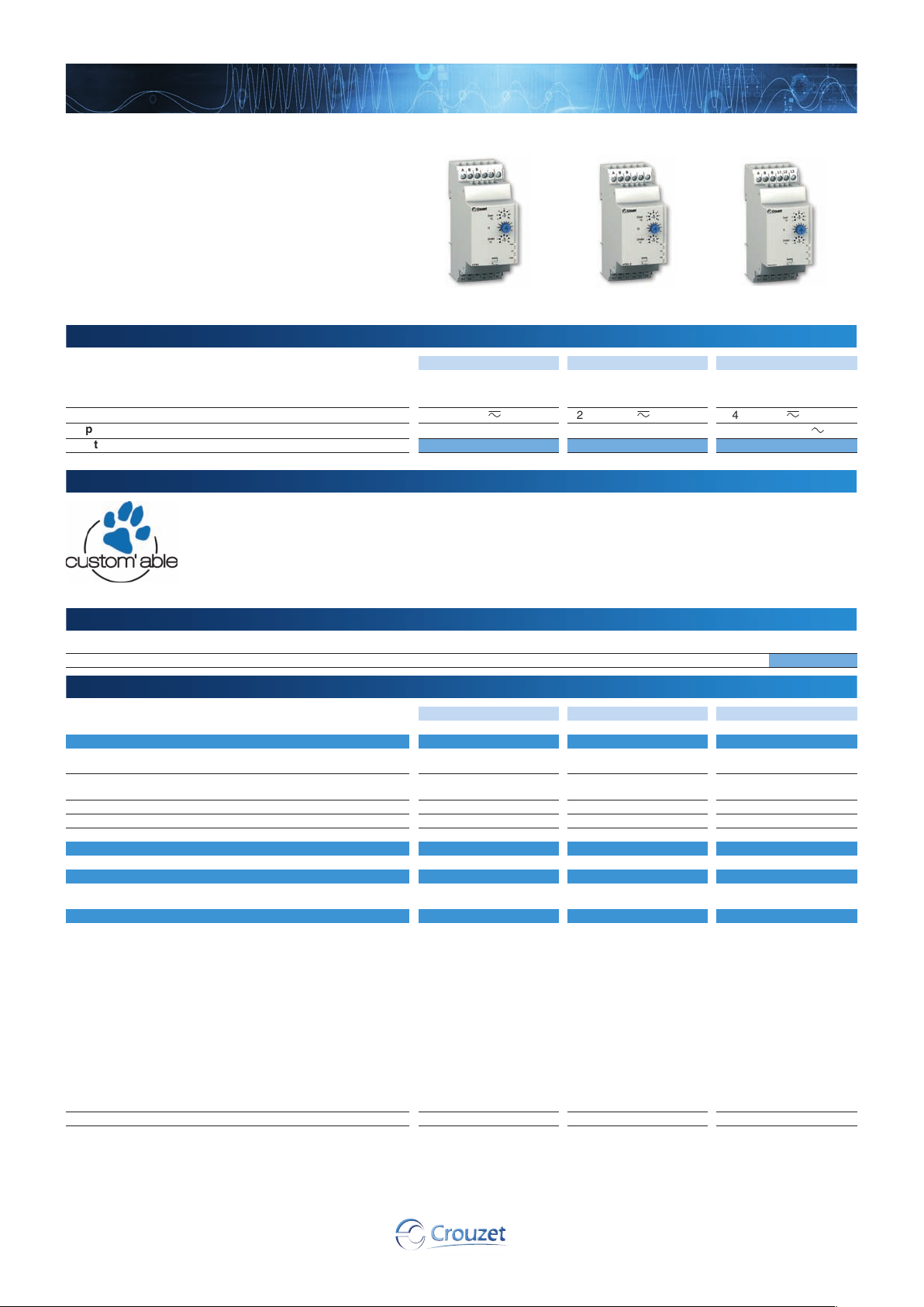
Temperature control in lifts according to EN81
HT81
HT81-2
HWT81
Part numbers
Product adaptations
Accessories
General characteristics
➜ Temperature control relay for lift service rooms - according to EN81 - 35 mm
■ Control relay designed to monitor the temperature in
lift machine rooms in accordance with standard EN81
■ PT100 input
■ Adjustable control between 5 °C and 40 °C
■ Independent setting of high and low thresholds
■ Built-in phase control option
Function Under/Overtemperature
Nominal voltage (V)
3-phase control -Part numbers 84874110 84874120 84874130
HT81 HT81-2 HWT81
window mode
➞ 240 V
z
24
Under/Overtemperature
window mode
24 ➞ 240 V
z
Under/Overtemperature
window mode + phase
sequence and failure
24 ➞ 240 V
3 x 208
z
➞ 480 V
a
■ Customisable colours and labels
■ Fixed threshold in the generic measurement range
■ Fixed or adjustable time delay
■ Adjustable fixed hysteresis
Description Code
Removable sealable cover for 35 mm casing 84800001
HT81 HT81-2 HWT81
Inputs and measuring cicuit
Phase control voltage range - - 208 V ➞ 480 V
Phase failure detection with regeneration - - > 30% of the average of
Frequency of measured signal - - 50
Relay drop-out voltage (phase failure) - - 70%
3-phase input resistors - - 600 KΩ
Timing
Maximum response time in the event of a 3-phase fault (ms) - - 500 ms
Output
Type of output 1 single pole changeover
Insulation
Galvanic isolation of power supply/measurement Yes, between power
Nominal insulation voltage IEC 60664-1 250 V 250 V 400 V
relay
supply and PT100
(transformer)
Yes, between power
supply and output
(transformer and relay)
Yes, between PT 100
and output (relay)
2 single pole NO relay 2 single pole NO relay
Yes, between power
supply and PT100
(transformer)
Yes, between power
supply and output
(transformer and relay)
Yes, between PT100 and
output (relay)
(-15% / +10%) *
the 3 phases
➞ 60 Hz ± 1 Hz
Yes, between power supply
and PT100 (transformer)
Yes, between power supply
and output (transformer and
relay)
Yes, between power supply
and 3-phase network
(transformer) Yes, between
3-phase network and output
(relay)
No, between 3-phase
network and PT100
(leakage current limited by
several high-value resistors)
Yes, between PT 100 and
output (relay)
62
www.crouzet.com
General characteristics
HT81 / HT81-2 / HWT81
Supply
Supply voltage Un
Voltage supply tolerance
24 V
-15%, + 10% in
-10%, +10% in
Operating range
20.4 V
21.6 V ➞ 264 V
Polarity with DC voltage No
a
supply voltage frequency
Power consumption at Un
50 / 60 Hz ±10%
3.5 VA in
Immunity from micro power cuts 10 ms
Inputs and measuring cicuit
Low temperature measurement selection -1°C, 1°C, 3°C, 5°C, 7°C, 9°C, 11°C
High temperature measurement selection 34°C, 36°C, 38°C, 40°C, 42°C, 44°C, 46°C
Temperature measurement input resistance 1330 Ω
Fixed hysteresis 2 °C
Display precision ± 2%
Max. length of PT100 probe cables 10 m
Timing
Delay on treshold crossing 1
➞ 10 s
Display precision 0, + 10%
Reset time 8 s
Delay on pick-up 200 ms
Maximum response time on disappearance of fault 3.5 s for a temperature fault, 500 ms for a phase fault
Output
Type of contacts No cadmium
Maximum breaking voltage
Max. breaking current
Min. breaking current
Electrical life (number of operations)
Breaking capacity (resistive)
250 V
z
5 A
10 mA / 5 V
1 x 10
1250 VA
Maximum rate 360 operations/hour at full load
Operating categories acc. to IEC 60947-5-1 AC 12, AC 13, AC 14, AC 15, DC 12, DC 13, DC 14
Mechanical life (operations)
30 x 10
Insulation
Insulation coordination (IEC 60664-1 / 60255-5) Overvoltage category III: degree of pollution 3
Rated impulse withstand voltage IEC 60664-1/60255-5 4 kV (1.2 / 50 µs)
Dielectric strength IEC 60664-1/60255-5
Insulation resistance IEC 60664-1 / 60255-5
2 kV
> 100 MΩ - 500 V
General characteristics
Display power supply Green LED
Display temperature Yellow LED (HWT81)
Display phases Yellow LED (HWT81)
High threshold relay Yellow LED (HT81, HT81-2)
Low threshold relay Yellow LED (HT81, HT81-2)
Casing 35 mm
Mounting On 35 mm symmetrical DIN rail, IEC/EN 60715
Mounting position All positions
Material: enclosure plastic type VO to UL94 standard Incandescent wire test according to IEC 60695-2-11 & NF EN 60695-2-11
Protection (IEC 60529) Terminal block: IP 20
IP 30 casing
Weight 121 g
Connecting capacity IEC 60947-1
Max. tightening torques IEC 60947-1 0.6
Operating temperature IEC 60068-2 -20
Storage temperature IEC 60068-2 -40
Rigid: 1 x 4
1 x 11 AWG - 2 x 14 AWG
Flexible with ferrules: 1 x 2.5
1 x 14 AWG - 2 x 16 AWG
➞ 1 Nm / 5.3 ➞ 8.8 Lbf.In
➞ +50°C
➞ +70°C
Humidity IEC 60068-2-30 2 x 24 hr cycle 95% RH max. without condensation 55°C
Vibrations according to IEC/EN60068-2-6 10
➞ 150 Hz, A = 0.035 mm
Shocks IEC 60068-2-6 5 g
Standards
Marking CE (LVD) 73/23/EEC - EMC 89/336/EEC
Product standard NF EN 60255-6 / IEC 60255-6 / UL 508 / CSA C22.2 N°14 / EN 81-1
Electromagnetic compatibility Immunity EN 61000-6-2/IEC 61000-6-2
Certifications UL, CSA, GL
Emission EN 61000-6-4/EN 61000-6-3
IEC 61000-6-4/IEC 61000-6-3
Emission EN 55022 class B
pending
Conformity with environmental directives RoHS, WEEE
Comments
* 3-phase mains with earth
➞ 240 V
➞ 264 V
a
/0.6 W in
z
c
4
a
6
a
50 Hz 1 min.
2
- 2 x 2.52 mm2
z
a
c
a
c
c
c
2
- 2 x 1.52 mm
2
63

Overview
Temperature control in lifts according to EN81
Principles
Tt
1
5
5
6
2
3
4
7
U
Tt
Temperature control relays for lift machine rooms are designed for monitoring the temperature between 5 °C and 40 °C according to standard EN81.
HT81 - Under/Overtemperature HT81 operating principle:
U
1
2
R
High threshold
B
Low threshold
C
Hysteresis
D
Monitored temperature
E
Threshold crossing delay adjustable on
F
Tt
5
Tt
As long as the temperature controlled by the PT100 stays between the two preset thresholds on
the front face, the output relay is closed and the yellow LEDs are lit.
When the temperature exceeds one of the preset thresholds on the front face (upper or lower
threshold), the preset time delay on the front face (Tt) is activated. The yellow LED corresponding
to the threshold exceeded (upper or lower) flashes.
At the end of the time delay, if the temperature still exceeds one of the preset thresholds, the
3
output relay opens and the yellow LED corresponding to the threshold is extinguished.
4
The output relay closes instantaneously (at about the response time for disappearance of a fault)
3
when the temperature returns within the window of the two preset thresholds on the front face
plus (or minus) the fixed hysteresis.
If the PT100 probe is wired incorrectly (missing or short-circuited) the output relays opens and all
3 LEDs flash.
front face (Tt)
HT81-2 - Under/Overtemperature HT81-2 operating principle:
High threshold
B
Low threshold
C
Low threshold relay R1
D
High threshold relay R2
E
Hysteresis
F
Monitored temperature
G
Threshold crossing delay adjustable on
H
As long as the temperature controlled by the PT100 stays between the two preset thresholds on
the front face, the output relays are closed and their yellow LEDs are lit.
When the temperature exceeds one of the preset thresholds on the front face (upper or lower
threshold), the preset time delay on the front face (Tt) is activated. The yellow LED corresponding
to the threshold exceeded (upper or lower) flashes.
At the end of the time delay, if the temperature is still beyond one of the preset thresholds, the
corresponding output relay opens and the yellow LED corresponding to the threshold exceeded is
extinguished.
The output relay closes instantaneously (at about the response time for disappearance of a fault)
when the temperature returns within the window of the two preset thresholds on the front face
plus (or minus) the fixed hysteresis.
If the PT100 probe is wired incorrectly (missing or short-circuited) the output relays open and all 3
LEDs flash.
front face (Tt)
HWT81 - Under/Overtemperature
U
1
2
R1
High threshold
B
Low threshold
C
Hysteresis
D
Monitored temperature
E
Threshold crossing delay adjustable on
F
Tt
5
Tt
HWT81 operating principle:
As long as the temperature controlled by the PT100 stays between the two preset thresholds on
the front face, the temperature relay is closed.
When the temperature exceeds one of the preset thresholds on the front face (upper or lower
threshold), the preset time delay on the front face (Tt) is activated. The yellow temperature LED
3
(R1) flashes. At the end of the time delay, if the temperature still exceeds the preset threshold,
4
the output relay opens and the yellow LED is extinguished.
3
The output relay R1 closes instantaneously when the temperature returns within the window of
the two preset thresholds on the front face plus or minus the fixed hysteresis.
The unit also monitors correct sequencing of phases L1, L2 and L3 of the 3-phase network and
the total phase failure in the event of phase regeneration (<70%).
After a time delay on pick-up (t) and as long as the presence and sequence of the phases are
correct, relay R2 and the R2 "phase" LED are active. When a fault appears, the "phase" relay
opens and the R2 "phase" LED is extinguished instantly (response time from the appearance of a
fault).
On disappearance of the fault, both relay R2 and the phase control LED are activated (response
time from the disappearance of a fault). See "Phase failure and phase sequence" curve on page 67.
If the PT100 probe is wired incorrectly (missing or short-circuited), output relay R1 opens and the
yellow R1 LED flashes.
front face (Tt)
64

Dimensions (mm)
3,5
www.crouzet.com
60
44
23,2
35
45
67,5
Connections
HT81
l ≤ 10 m (393.7 in)
AB
B
A1
A2
A1 A2
1
F1
+/–
~
–/+
1 A fast-blow fuse or cut-out
B
HWT81
l ≤ 10 m (393.7 in)
12
L1
L2
L3
11
14
1112 14
90
2,6
5,5
HT81-2
l ≤ 10 m (393.7 in)
Pt 100
ABB
21
11
R
A1
A1 A2
1
F1
+/–
R1 R2
A2
24
14
21 2411 14
Pt 100
~
–/+
1 A fast-blow fuse or cut-out
B
– KM1
U1
V1
M1
3
W1
Pt 100
F1
+/–
~
–/+
1 A fast-blow fuse or cut-out
B
1
AB L1
11
R1 R2
L1L2L3
A2
A1
14
A1 A2
11 21 2414
L2 L3B
21
24
65
 Loading...