

Page 1
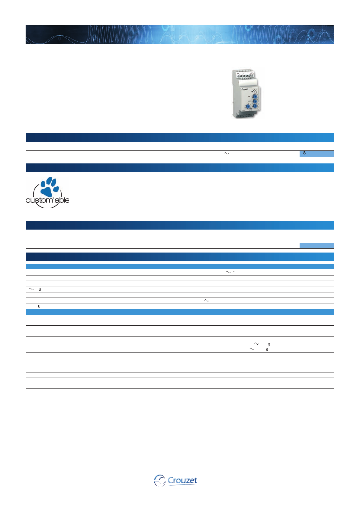
Phase control
HWUA
Part numbers
Product adaptations
Accessories
General characteristics
➜ Multi-function phase control relay 35 mm
■ Control of 3-phase networks: phase sequence, phase
failure, asymmetry, under and overvoltage with
independent settings
■ Multi-function/Multi-voltage product
■ Controls its own supply voltage
■ True RMS measurement
■ LED status indication
Type Functions Nominal voltage (V) Code
HWUA Phase sequence, failure, asymmetry, under/overvoltage
■ Customisable colours and labels
■ Single voltage in the generic range
■ Fixed undervoltage threshold in the generic range
■ Fixed overvoltage threshold in the generic range
■ Fixed asymmetry threshold in the generic range or adjustable 5➞ 25 %
■ Fixed or adjustable time delay
3 x 220
➞ 3 x 480 V
a
84873026
Description Code Description
Removable sealable cover for 35 mm casing
Supply
Supply voltage Un
Voltage supply tolerance -12% / +10%
Operating range 194
a
supply voltage frequency
Galvanic isolation of power supply/measurement No
Power consumption at Un
Immunity from micro power cuts 10 ms
Inputs and measuring cicuit
Measurement ranges 194
Selection of phase-phase nominal voltage Un 220 - 380 - 400 - 415 - 440 - 480 V
Frequency of measured signal 50
Max. measuring cycle time 140 ms/True RMS measurement
Voltage threshold adjustment 2
Asymmetry threshold adjustment 5
Fixed hysteresis Under or overvoltage, asymmetry: 2% of the Un value of the selected
Display precision ± 3% of the displayed value
Repetition accuracy with constant parameters ± 0.5%
Measuring error with voltage drift < 1%
Measuring error with temperature drift 0.05%/°C
3 x 220
➞ 3 x 480 V
➞ 528 V
50 / 60 Hz ± 10%
2.9 VA in
(+2
-12 to -2% across the 3 x 220 V
network
Asymmetry: 2% of the Un value of the selected network
a
➞ 528 V
➞ 60 Hz ± 10%
➞ 20% of selected Un
➞ +10% across the 3 x 480 V
➞ 15% of fixed Un
a
*
a
range
a
range
Code
84800001
22
Page 2
www.crouzet.com
General characteristics
Timing
Delay on threshold crossing 0.1
Repetition accuracy with constant parameters ± 0.3%
Reset time 1.5 s
Delay on pick-up 500 ms
Alarm on delay time max. < 200 ms
Output
Type of output 1 double changeover relay
Type of contacts No cadmium
Maximum breaking voltage
Max. breaking current
Min. breaking current
Electrical life (number of operations)
Breaking capacity (resistive)
Maximum rate 360 operations/hour at full load
Operating categories acc. to IEC 60947-5-1 AC 12, AC 13, AC 14, AC 15, DC 12, DC 13, DC 14
Mechanical life (operations)
Insulation
Nominal insulation voltage IEC 60664-1 400 V
Insulation coordination (IEC 60664-1 / 60255-5) Overvoltage category III: degree of pollution 3
Rated impulse withstand voltage IEC 60664-1/60255-5 4 KV (1.2 / 50 µs)
Dielectric strength IEC 60664-1/60255-5 2 kV AC 50 Hz 1 min
Insulation resistance IEC 60664-1 / 60255-5
General characteristics
Display power supply Green LED
Display relay Yellow LED
"Fault" indication Yellow LED
Casing 35 mm
Mounting On 35 mm symmetrical DIN rail, IEC/EN 60715
Mounting position All positions
Material: enclosure plastic type VO to UL94 standard Incandescent wire test according to IEC 60695-2-11 & NF EN 60695-2-11
Protection (IEC 60529) Terminal block: IP 20
Weight 130 g
Connecting capacity IEC 60947-1
Max. tightening torques IEC 60947-1 0.6
Operating temperature IEC 60068-2 -20
Storage temperature IEC 60068-2 -40
Humidity IEC 60068-2-30 2 x 24 hr cycle 95% RH max. without condensation 55°C
Vibrations according to IEC/EN60068-2-6 10
Shocks IEC 60068-2-6 5 g
Standards
Marking CE (LVD) 73/23/EEC - EMC 89/336/EEC
Product standard NF EN 60255-6 / IEC 60255-6 / UL 508 / CSA C22.2 N°14
Electromagnetic compatibility Immunity EN 61000-6-2/IEC 61000-6-2
Certifications UL, CSA, GL
Conformity with environmental directives RoHS, WEEE
Comments
➞ 10s (0, +10%)
z
250 V
z
5 A
10 mA / 5 V
1 x 10
1250 VA
30 x 10
> 500 MΩ / 500 V
c
5
a
6
c
Extinguished in the event of phase failure
Flashes during the threshold crossing delay
Lights up in the event of asymmetry
Flashes in the event of under or overvoltage
Casing: IP 30
Rigid: 1 x 4
1 x 11 AWG - 2 x 14 AWG
Flexible with ferrules: 1 x 2.5
1 x 14 AWG - 2 x 16 AWG
Emission EN 61000-6-4/EN 61000-6-3
IEC 61000-6-4/IEC 61000-6-3
Emission EN 55022 class B
2
- 2 x 2.52 mm2
➞ 1 Nm / 5.3 ➞ 8.8 Lbf.In
➞ +50°C
➞ +70°C
➞ 150 Hz, A = 0.035 mm
2
- 2 x 1.52 mm
pending
* 3-phase mains with earth
2
23
Page 3
Overview
Phase control
Principles
L1
L2
L3
Tt
Tt
Tt
5
6
1
3
4
2
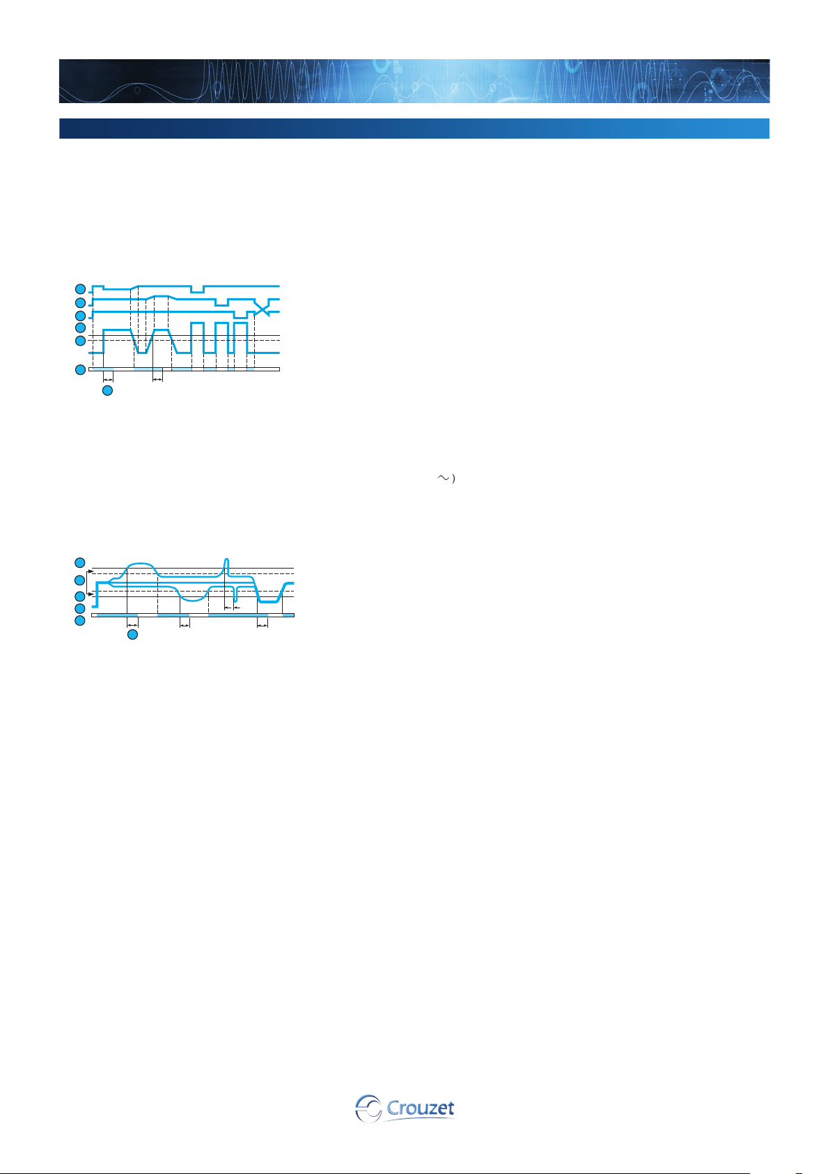
The HWUA 3-phase network control relay monitors:
- The correct sequence of phases L1, L2, L3
- Total phase failure
- Undervoltage and overvoltage from 2 to 20 % of Un
- Asymmetry rate from 5 to 15% of Un
- Faults are signalled via LEDs, distinguishing the origin of the fault.
If a fault persists for longer than the threshold crossing delay configured by the user, both output relays open and LED R is extinguished.
HWUA - Failure, phase sequence and asymmetry Operating principle
HWUA: Phase + Asymmetry + Under/Overvoltage controller
1
2
3
4
5
0 %
6
R
Tt
7
Phase L1
B
Phase L2
C
Phase L3
D
Asymmetry threshold
E
Hysteresis
F
Relay
G
Delay on threshold crossing (Tt)
H
Tt
L3
L2
Voltage selector switch:
Set the selector switch to the 3-phase network voltage Un.
The position of this selector switch is only taken into account when the unit is powered up.
If the switch position changes while the unit is operating, all the LEDs flash but the product
continues to work normally with the voltage selected on energisation prior to the change of
position.
The LEDs return to their normal state if the switch is reset to its initial position defined before the
last energisation.
The relay monitors its own supply voltage.
The relay controls:
- correct sequencing of the three phases,
- failure of one of the three phases (U measured < 0.7 x Un),
- asymmetry, adjustable from 5 to 15% of Un,
- undervoltage adjustable from - 2 to - 20% of Un, (-2 to -12% for the 220 V range) and
overvoltage adjustable from +2 to +20% (+2 to +10% over the 3 x 480 V range due to the
maximum voltage 528 V
In the event of a phase sequence or failure fault, the relay opens instantaneously.
In the event of an asymmetry or voltage fault, the relay opens at the end of the time delay set by
HWUA - Under/Overvoltage
Overvoltage
B
Hysteresis
C
Undervoltage
D
Phases L1, L2, L3
E
Relay
F
Delay on threshold crossing (Tt)
G
a
).
24
Page 4
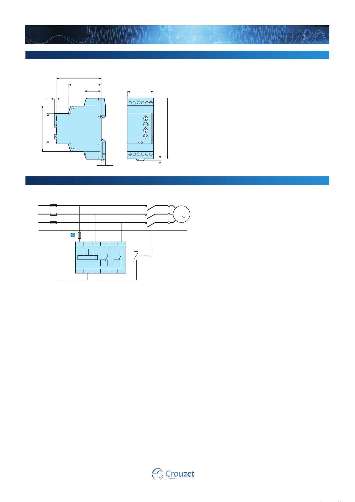
Dimensions (mm)
HWUA
3,5
www.crouzet.com
60
44
23,2
35
45
67,5
Connections
HWUA
L1
L2
L3
N
100 mA fast-blow fuse
B
F1
1
L1 L2
L1
11 21 2412 2214
90
2,6
5,5
– KM1
L3
21
L2
11
L3
R1 R2
22
12
24
14
U1
W1
V1
M1
3
25
 Loading...