


Current control
HIL
HIH
Part numbers
Product adaptations
Accessories
General characteristics
➜ Multi-function current control relay - 35 mm
■ Control of AC and DC currents
■ Automatic recognition of AC/DC
■ Measurement ranges from 2 mA to 10 A
■ Choice between over and undercurrent
■ True RMS measurement
■ Selectable latching (memory) function
Functions Over or undercurrent Over or undercurrent
Measurement range 2 mA
Nominal voltage (V)
Part numbers 84871120 84871130
HIL HIH
➞ 500 mA 0.1 A ➞ 10 A
➞ 240 V
z
24 ➞ 240 V
24
z
■ Customisable colours and labels
■ Measuring ranges within the generic limits
■ Fixed threshold in the generic measurement range
■ Fixed or adjustable time delay
■ Adjustable hysteresis
Description Code
Removable sealable cover for 35 mm casing 84800001
HIL HIH
Inputs and measuring cicuit
Measurement range 2 ➞ 500 mA
Input resistance E1 - M: 5 Ω
Permanent overload at 25°C E1 - M: 0.4 A
Pulse overload < 1 sec at 25°C E1 - M: 1 A
E1 - M: 2 ➞ 20 mA
E2 - M: 10
E3 - M: 50
E2 - M: 1 Ω
E3 - M: 0.2 Ω
E2 - M: 1 A
E3 - M: 2 A
E2 - M: 5 A
E3 - M: 8 A
➞ 100 mA
➞ 500 mA
0.1
➞ 10 A
E1 - M: 0.1 ➞ 1 A
E2 - M: 0.5
E3 - M: 1
E1 - M: 0.1 Ω
E2 - M: 0.02 Ω
E3 - M: 0.01 Ω
E1 - M: 2 A
E2 - M: 11 A
E3 - M: 11 A
E1 - M: 17 A
E2 - M: 20 A
E3 - M: 50 A
➞ 5 A
➞ 10 A
40

www.crouzet.com
General characteristics
Supply
Supply voltage Un
24 V
Voltage supply tolerance -15% / +10%
Operating range
20.4 V
Polarity with DC voltage No
a
supply voltage frequency
Galvanic isolation of power supply/measurement
50 / 60 Hz ± 10%
✓
Power consumption at Un 3.5 VA in AC/0.6 W in DC
Immunity from micro power cuts 50 ms
Inputs and measuring cicuit
Frequency of measured signal 0 Hz, 40
Max. measuring cycle time 30 ms/True RMS measurement
Threshold adjustment 10
➞ 100% of the range
Maximum 3-phase voltage 277 / 480 V (3-phase mains with earth)
Adjustable hysteresis 5
➞ 50% of displayed threshold
Display precision ±10% of full scale
Repetition accuracy with constant parameters ± 0.5%
Measuring error with voltage drift ± 1% across the whole range
Measuring error with temperature drift ± 0.05% / °C
Timing
Delays on power up 1
Delay on threshold crossing 0.1
➞ 20 s 0, +10%
➞ 3 s 0, +10%
Repetition accuracy with constant parameters ± 2%
Reset time 1500 ms
Delay on pick-up < 300 ms
Output
Type of output 1 double changeover relay
Type of contacts No cadmium
Maximum breaking voltage
Max. breaking current
Min. breaking current
Electrical life (number of operations)
Breaking capacity (resistive)
250 V
z
5 A
10 mA / 5 V
1 x 10
1250 VA
Maximum rate 360 operations/hour at full load
Operating categories acc. to IEC 60947-5-1 AC12, AC13, AC14, AC15, DC12, DC13, DC14
Mechanical life (operations)
30 x 10
Insulation
Nominal insulation voltage IEC 60664-1 250 V
Insulation coordination (IEC 60664-1 / 60255-5) Overvoltage category III: degree of pollution 3
Rated impulse withstand voltage IEC 60664-1/60255-5 4 KV (1.2 / 50 µs)
Dielectric strength IEC 60664-1/60255-5
Insulation resistance IEC 60664-1 / 60255-5
2 KV
> 500 MΩ / 500 V
General characteristics
Display power supply Green LED
Display relay Yellow LED
Casing 35 mm
Mounting On 35 mm symmetrical DIN rail, IEC/EN 60715
Mounting position All positions
Material: enclosure plastic type VO to UL94 standard Incandescent wire test according to IEC 60695-2-11 & NF EN 60695-2-11
Protection (IEC 60529) Terminal block: IP 20
Casing: IP 30
Weight 130 g
Connecting capacity IEC 60947-1
Max. tightening torques IEC 60947-1 0.6
Operating temperature IEC 60068-2 -20
Storage temperature IEC 60068-2 -40
Rigid: 1 x 4
1 x 11 AWG - 2 x 14 AWG
Flexible with ferrules: 1 x 2.5
1 x 14 AWG - 2 x 16 AWG
➞ 1 Nm / 5.3 ➞ 8.8 Lbf.In
➞ +50°C
➞ +70°C
Humidity IEC 60068-2-30 2 x 24 hr cycle 95% RH max. without condensation 55°C
Vibrations according to IEC/EN60068-2-6 10
➞ 150 Hz, A = 0.035 mm
Shocks IEC 60068-2-6 5 g
Standards
Marking CE (LVD) 73/23/EEC - EMC 89/336/EEC
Product standard NF EN 60255-6 / IEC 60255-6 / UL 508 / CSA C22.2 N°14
Electromagnetic compatibility Immunity EN 61000-6-2/IEC 61000-6-2
Certifications UL, CSA, GL
Emission EN 61000-6-4/EN 61000-6-3
IEC 61000-6-4/IEC 61000-6-3
Emission EN 55022 class B
pending
Conformity with environmental directives RoHS, WEEE
➞ 240 V
➞ 264 V
➞ 70 Hz
z
c
5
a
6
a
50 Hz 1 min.
2
- 2 x 2.52 mm2
z
z
c
2
- 2 x 1.52 mm
2
41
HIL-HIH
Current control
Principles
Un
Tt
Ti
Ti Tt
Ti Tt
1
1
3
4
7 8
5
6
6
2
2
Ti
Tt
Overview
HIL and HIH control relays are designed to control AC or DC currents.
They automatically recognise the shape of the DC or AC signal (50 or 60 Hz) and can control up to 10 A in DC. Above this level, a current transformer can
be connected.
General principle:
The operating mode is set by the user.
A switch is used to select over or undercurrent modes, with or without latching.
The switch position, and hence the operating mode, is read by the product on energisation.
If the switch is set to a non-conforming position, the product goes into fault mode, the output relay stays open, and the LEDs flash to signal the position
error.
If the switch position changes while the unit is operating, all the LEDs flash but the product continues to work normally with the function selected on
energisation prior to the change of position.
The LEDs return to their normal state if the switch is reset to its initial position defined before the last energisation.
The over or undercurrent threshold value is set by a graduated potentiometer as a percentage of the I scale to be monitored.
The hysteresis is set by a graduated potentiometer from 5 to 50% of the preset threshold. The hysteresis value cannot be higher than the extremes of the
measurement range.
An adjustable time delay from 1 to 20 s on energisation is used to prevent current peaks or troughs on starting.
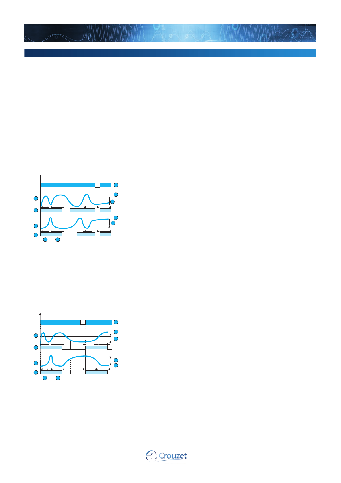
HIL-HIH - Under/overcurrent - without latching
In overcurrent mode, if the controlled current exceeds the preset threshold for longer than the
time set on the front face (0.1 to 3 s), the output relay opens and LED R is extinguished. During
the time delay, this LED flashes.
Once the current falls below the threshold value minus the hysteresis, the relay closes
instantaneously.
In undercurrent mode, if the controlled current falls below the preset threshold for longer than the
time set on the front face (0.1 to 3 s), the output relay opens and LED R is extinguished. During
the time delay, this LED flashes.
Once the current rises above the threshold value plus the hysteresis, the relay closes
instantaneously.
Threshold
B
Hysteresis
C
Overcurrent function relay
D
Undercurrent function relay
E
Unit power-up
F
Controlled current
G
Inhibit delay on starting (Ti)
H
Delay on upward threshold crossing (Tt)
I
HIL-HIH - Under/overcurrent - with latching
Un
1
Tt
Ti
3
1
Ti
Tt
7 8
4
Threshold
B
Hysteresis
C
Overcurrent function relay
D
Undercurrent function relay
E
Unit power-up
F
Controlled current
G
Inhibit delay on starting (Ti)
H
Delay on upward threshold crossing (Tt)
I
42
If "with memory" mode has been selected, the relay opens and stays in this position when
threshold crossing is detected.
5
6
2
Tt
Ti
2
Ti
6
Tt
The power supply must be disconnected to reset the product.

Dimensions (mm)
HIL-HIH
3,5
www.crouzet.com
60
44
23,2
35
45
67,5
Connections
HIL-HIH
L2
L1
–/+
a /c
+/–
1 A fast-blow fuse or cut-out
B
1
F1
A1 A2 E3 E2 E1 M
A1
A2
12
12 11 14 22 21 24
90
2,6
5,5
– KM1
11
21
W1
U1
M1
3
R
22
14
24
NB:
When controlling DC current from the same source supplying terminals A1 and A2, terminal M must be connected directly to the "minus" pole of
this power supply.
43
 Loading...