


DIN Rail Mount 45 mm FN Part number 84870502
Automatic control and regulation of liquid levels.
2 sensitivity ranges.
Filling or emptying function selected via dip switch.
High or low alarm selected via dip switch.
Memory can be selected.
LEDs indicate state of power supply, output relay and alarm relay.
Part numbers
Specifications
Type
Voltages
84 870 502
FN
48 VAC
Supply voltage Un
230, 120, 48 and 24 V AC 50/60 Hz galvanic isolation via transformer
Operating range
0.85 to 1.15 Un except 120 V AC : 0.85 to 1.1 Un
Nominal power
3 VA at Un
Maximal power
4 VA at Un + 15 %
Immunity from micro power cuts
10 ms Delay on pick
-up
T1 = approx. 2 s
Response time on power up
T4 = 500 ms
Insulation coordination
Category III, degree of pollution 2 conforming to IEC/EN 60664
-1 : 4 kV/2
Sensitivity range FN
5 k
Ω
→100k
Ω
Sensitivity range FHLS
250
Ω
→5k
Ω
Display precision
±
30 % with maximum sensitivity
Electrode voltage
15 V AC (50/60 Hz)
Electrode current
1 mA Response time on immersion
T2 = 400 ms
Response time on emersion
T3 = 700 ms
Output
2 AgCdO changeover
Breaking capacity
FN LS : 2000 VA
FN : 80 W
Maximum breaking current
FN LS : 8 A AC
FN : 8 A DC
Minimum breaking current
FN LS : 100 mA AC
FN : 100 mA DC
Max. breaking voltage
FN LS : 250 V AC
FN : 250 V DC
Mechanical life (operations)
2 x 10
6
Electrical life AC 12
2000 VA - 105 operations
Electrical life AC 15
Cos φ=
0,3 - 6000 operations
Electrical life AC 13
L/R = 300 ms
- 6000 operations
Housing material
Self-extinguishing
Terminal capacity
2 x 1,5 mm2 with ferrule
2 x 2,5 mm2 without ferrule
Temperature limit operation (IEC 68.1.14)
(°C)
-
20→+60
Temperature limits stored (IEC 68.1.1/2)
(°C)
-
30→+70
Relative humidity (no condensation)
93 % (+2 % ; -3 %)
Weight (g)
280
* Création *
TRADOS Empty Field
Principles
20/10/2014 www.crouzet.com
Unless otherwise specified, the characteristics given are applicable to all or part of the product range selected
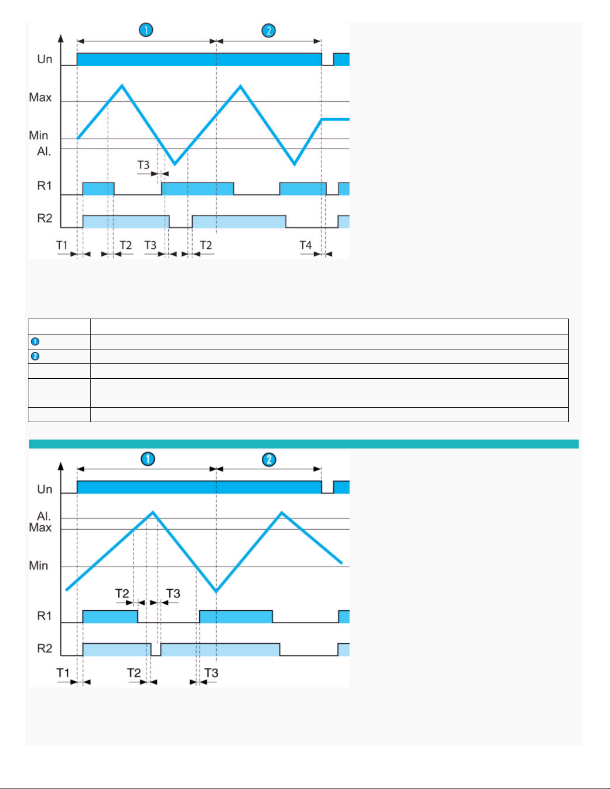
On power-up, probe AI. is submerged, relays R1 and R2 are energised and the pump is ON : filling starts, the LED for relay R1 is lit. When the level reaches the Max probe, relay R1 de-energises
and the pump is OFF : filling stops, the LED for relay R1 goes off. Relay R1 re
-energises when the Min probe emerges. In the event of a fault (level continues to fall) probe AI. emerges, relay R2 deenergises ans the alarme is triggered : the LED for relay R2 is lit.
This fault can be stored
On power-up, the level in the tank is low, relays R1 and R2 are energised and the pump is ON : filling starts, the LED for relay R1 is lit. When the level reaches the Max probe, relay R1 de-energises
and the pump is OFF : filling stops, the relay LED goes off. If, in the event of a fault, the level continues to rise and reaches proble AI., relay R2 de-energises and the alarme is triggered : the LED for
relay R2 is lit.
This fault can be stored.
N
o
Legend
Memory OFF
Memory ON
T1 : Delay on pick
-up
T2 : Response time on immersion
T3 : Response time on emersion
T4 : Response time on power-down
Principles
20/10/2014 www.crouzet.com
Unless otherwise specified, the characteristics given are applicable to all or part of the product range selected

On power-
up, probes Min, Max and AI. are submerged, relays R1 and R2 are energised and the pump is ON : emptying starts, the LED for relay R1 is lit. When the Min probe emerges, relay R1 goes
off. If, in the event of a fault, the level continues to fall and probe AI. emerges, relay R2 de-
energises and the alarm is triggered : the LED relay R2 is lit.
This fault can be stored.
N
o
Legend
Memory OFF
Memory ON
T1 : Delay on pick
-up
T2 : Response time on immersion
T3 : Response time on emersion
Principles
N
o
Legend
Memory OFF
Memory ON
T1 : Delay on pick
-up
T2 : Response time on immersion
T3 : Response time on emersion
Principles
20/10/2014 www.crouzet.com
Unless otherwise specified, the characteristics given are applicable to all or part of the product range selected

On power-
up, probes Min, Max are submerged and probe AI. is above the level of the liquid. Relays R1 and R2 are energised and the pump is ON : emptying starts, the LED for relay R1 is lit. When
the Min probe emerges, relay R1 de
-energises and the pump if OFF : emptying stops, the LED for relay R1 goes off. If, in the event of a fault, the level continues to rise a
nd reaches proble AI., relay R2 de-
energises and the alarm is triggered : the LED for relay R2 is lit.
This fault can be stored.
Operating principle
Control of the level of a conductive liquid at specific points (high and low levels) with an alarm for a level which is abnormally high or low.
The principle is based on measurement of the apparent resistance of the liquid between submerged probes. When this value is lower than the present threshold on the unit front face, the output
relay R1 and/or the alarm relay R2 change state.
The avoid electrolytic phenomena, an AC current runs across the probes.
Adjusting sensitivity
Set the sensitivity so that the relay will change state when the probes are in contact with the liquid. Then check that the relay returns to its initial position as soon as the probes emerge.
In certain applications, fine-tuning the sensitivity prevents inappropriate detection, such as the presence of foam or bubbles on the surface or the occurrence of leakage impedance between
probes (extended line capacity, humidity, etc).
Note :
Latching of the alarm relay R2 in de
-energised state if a fault occurs can the programmed via a switch on the underside of the underside of the unit (only when the unit is switched off). To reset
alarm relay R2, cut the power, as long as the levels are reset.
Programming
The FN level controller can be programmed using 3 switches on the lower panel :
Note :
Memory, Alarme and Function must only be selected when the unit is switched off.
N
o
Legend
Memory OFF
Memory ON
T1 : Delay on pick
-up
T2 : Response time on immersion
T3 : Response time on emersion
T4 : Response time on power-down
Principles
N
o
Legend
20/10/2014 www.crouzet.com
Unless otherwise specified, the characteristics given are applicable to all or part of the product range selected

Note : If case of metalic tank, it could be used as probe (C). A green LED indicates the presence of the supply voltage A yellow LED indicates the satus of the output relay
A red LED indicates the
status of the alarm
Memory
Alarm
Function
Low
Emptying
High
Filling
Dimensions (mm)
FN / FN LS
Connections
Regulating with "up" filling control
Legend
A1 - A2 : Supply voltage
20/10/2014 www.crouzet.com
Unless otherwise specified, the characteristics given are applicable to all or part of the product range selected

11 - 12 - 14 : Output relay (R1)
21 - 22 - 24 : Alarm output relay (R2)
C - Min - Max - Al. : Probe inputs
20/10/2014 www.crouzet.com
Unless otherwise specified, the characteristics given are applicable to all or part of the product range selected
 Loading...