

Page 1
Level control
➜ ENRM
■ Regulation of 1 or 2 levels (minimum / maximum)
■ Monitoring filling (UP) or emptying (DOWN) selected by a
switch on the front panel
■ Probes supplied with AC current
■ Sensitivity adjustable on front panel from 250 Ω to 1 M Ω
■ Time delay preventing wave effect adjustable from 0.1 to 5s
Part numbers
Type Characteristics Voltages Code
ENRM Monitoring filling (UP)
Monitoring emptying (DOWN)
24
General characteristics
Characteristics
Supply voltage range
Operating range
Maximum power consumption a
Adjustable sensitivity 250 Ω
Measurement accuracy (at maximum sensitivity) ± 30 %
Electrode voltage (max)
Electrode current (maximum) 1 mA
Maximum cable capacity 10 nF
Response time high level 300 ms
Response time low level 500 ms
Output relay (according to AC1 resistive load) 1 AgNi changeover relay 8 A AC max.
Isolation of contacts and electrodes from power supply
Operating temperature range (°C) -20
Storage temperature range (°C) -40
Weight (g) 91
24
20.4
12 V
2.5 kV
z
➞ 240 V
z
➞ 240 V
➞ 264 V
z
5 VA, c 1.5 W
➞ 1 MΩ
a
a
➞ +50 °C
➞ +70 °C
84 870 210
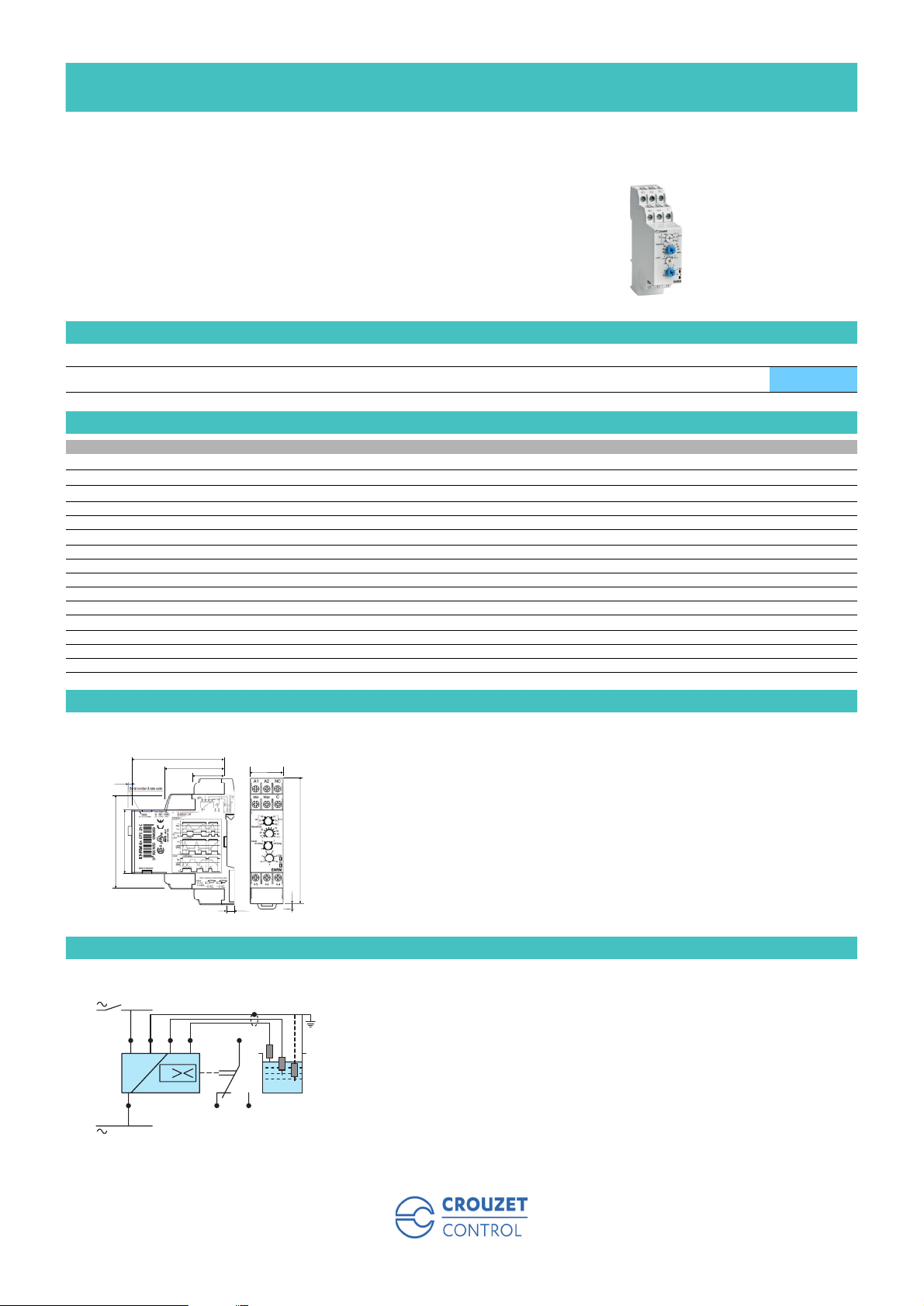
Dimensions (mm)
ENRM
68
3.5
67.5
45
44
Connections
ENRM
U
+
A1
C Min Max
U
_
23.2
22.5
90
5.5
11
R
12 14A2
2.6
1
Page 2
Principles
Operating principle
General principle :
The ENRM monitors the levels of conductive liquids. The principle is based on measuring the apparent resistance of the liquid between two submerged
probes. When this value is lower than the preset threshold displayed on the unit’s front panel, the relay changes state. To prevent any occurrences of
electrolysis, an AC current is passed through the probes. A rotary switch on the front panel can be used to select the desired function and sensitivity
range. A level can be monitored using the 2
In this instance, the max. probe remains above the liquid and an adjustable time delay prevents the wave effect.
A green LED indicates that the supply voltage is present.
A yellow LED indicates the output relay’s state.
When the green and yellow LEDs are flashing, this indicates an incompatible adjustment position.
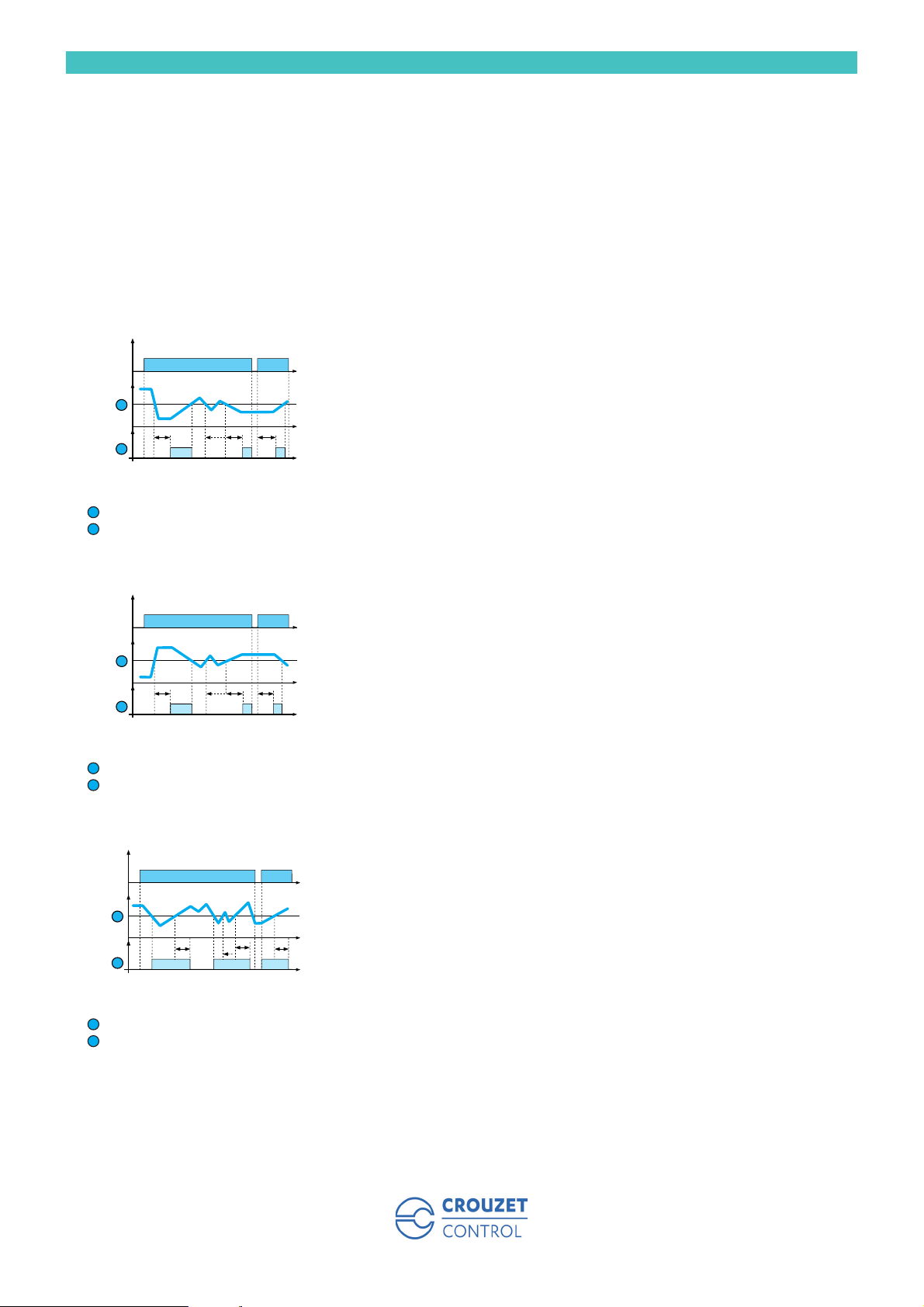
Rotary switch in mode 2 - Activation time - Filling function
U
1
TTT T
2
Level
1
Relay
2
nd
rotary switch.
Monitoring a level, filling function, activation time
(level : 1 - on delay, function Up LS (Low Sensitivity : 250 Ω to 5 kΩ ), Up St (Standard
Sensitivity : 5 kΩ to 100 kΩ), Up HS (High Sensitivity : 50 kΩ to 1 MΩ).
When the level of liquid drops below the probe for a period exceeding the value of time delay T
set on the front panel, the relay energises and remains on until the level of liquid reaches the
probe again.
If the level of liquid returns above the level set before the time delay elapses, the relay does not
come on.
Note
When the power returns after a power break, the output relay only energises after time delay T if
the level of liquid is below the threshold.
Rotary switch in mode 2 - Activation time - Emptying function
U
Monitoring a level, emptying function, activation time
(level : 1 - on delay, function Dwn LS (Low Sensitivity : 250 Ω to 5 kΩ ), Dwn St (Standard
Sensitivity : 5 kΩ to 100 kΩ), Dwn HS (High Sensitivity : 50 kΩ to 1 MΩ).
When the level of liquid rises above the probe for a period exceeding the value of time delay T set
1
TTT T
2
on the front panel, the relay energises and remains on until the level of liquid drops back below
the probe.
If the level of liquid drops back below the level set before the time delay elapses the relay does
not come on.
Note
When the power returns after a power break, the output relay only energises after delay time T if
the level of liquid is above the threshold.
Level
1
Relay
2
Rotary switch in mode 3 - Deactivation time - Filling function
U
Monitoring a level, filling function, deactivation time
(level : 1 - off delay, function Up LS (Low Sensitivity : 250 Ω to 5 kΩ) or Up St (Standard
Sensitivity : 5 kΩ to 100 kΩ) or Up HS (High Sensitivity : 50 kΩ to 1 MΩ).
When the liquid level drops below the probe the relay energises immediately and remains on until
1
the level of liquid reaches the probe again and remains above it for a period exceeding time delay
T set on the front panel.
T
2
T
T
T
If the level of liquid drops back below the level set before the time delay elapses, the relay
remains on.
Note
When the power returns after a power break, the output relay energises if the liquid level is below
the threshold.
Level
1
Relay
2
2
Page 3

Rotary switch in mode 3 - Deactivation time - Emptying function
U
Monitoring a level, emptying function, deactivation time
(level : 1 - off delay, function Dwn LS (Low Sensitivity : 250 Ω to 5 kΩ) or Dwn St (Standard
Sensitivity : 5 kΩ to 100 kΩ) or Dwn HS (High Sensitivity : 50 kΩ to 1 MΩ).
When the level of liquid rises above the probe the relay energises immediately and remains on
1
T
2
T
T
T
until the level of liquid drops back below the probe for a period exceeding the value of time delay
T set on the front panel.
If the level of liquid returns above the level set before the time delay elapses the relay remains on.
Note
When the power returns after a power break, the output relay energises if the level of liquid is
above the threshold.
Level
1
Relay
2
Monitoring two levels, emptying function
U
Monitoring two levels, emptying function
(level : 2, function Dwn LS (Low Sensitivity : 250 Ω to 5 kΩ), Dwn St (Standard Sensitivity : 5 kΩ
to 100 kΩ), Dwn HS (High Sensitivity : 50 kΩ to 1 MΩ ).
1
2
3
The output relay remains open as long as the level of liquid has not reached the maximum probe.
Once the maximum level is reached the contact closes and the tank can then be emptied (valve
opened, pump started, etc). When the level drops below the minimum level the contact opens
and interrupts the emptying process.
Note : when monitoring two levels the time delay preventing the wave effect is not in operation.
Note
When the power returns after a power break, the output relay energises if the level of liquid is
above the threshold.
Maximum level
1
Minimum level
2
Output relay : Down
3
Monitoring two levels, filling function
U
Monitoring two levels, filling function
(level : 2, function Up LS (Low Sensitivity : 250 Ω to 5 kΩ ) or Up St (Standard Sensitivity : 5 kΩ
to 100 kΩ) or Up HS (High Sensitivity : 50 kΩ to 1 MΩ).
1
2
3
The output relay remains on as long as the level of liquid has not reached the maximum probe.
As soon as the maximum level is reached the contact opens and pumping stops. When the level
drops below the minimum level the contact closes again and pumping restarts to bring the level of
liquid back up.
Note : When monitoring the two levels the time delay preventing the wave effect is not in
operation.
Note
When the power returns after a power break, the output relay energises if the level of liquid is
below the threshold.
Maximum level
1
Minimum level
2
Output relay : Up
3
Other information
Note
The probe cable (maximum length 100 metres) does not have to be screened, but avoid mounting it in parallel with the power supply cables. A screened
cable can be used with the screening connected to the common terminal.
3
 Loading...