

Page 1
Additional specifications
| MICROSWITCHES | 1 | SWITCHES.CROUZET.COM | 09/2020
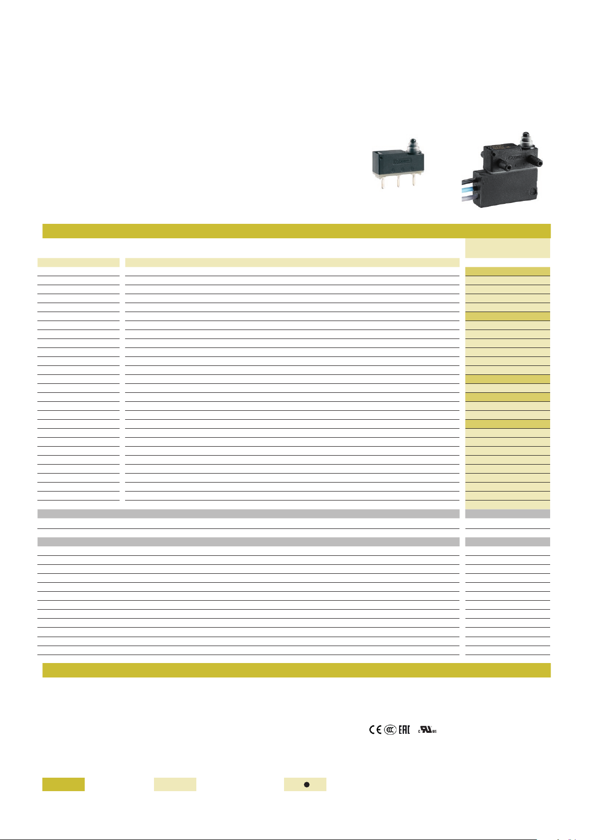
SUB-SUBMINIATURE MICROSWITCHES - SEALED
V5S - 8320
› High precision flexible leaf snap-action mechanism
› Operation without balance-point, even at extremely slow actuating speed
› Very small size
› Extra-long plunger stroke: 2 mm overtravel to absorb dispersions in application
› Suitable for lateral approach from any direction with angle up to 45°
› Excellent resistance to harsh environments - IP67/IP69 protection
› Use from 1 mA 4 Vc to 4 A 250 Va
› Long mechanical life
› Various terminal types and pre-wired models - Choice of flexible actuators
Main specifications
Dual-current
83200
Function Connections / Locating pins
I (changeover) X1 (PCB, straight) / none 83200003
I (changeover) X1 (PCB, straight) / CAR (two short, rear) 83200011
I (changeover) X1 (PCB, straight) / CAV (two short, front) 83200012
I (changeover) X1 (PCB, straight) / LAV, LAR, 4C, 4L
I (changeover) X1L (PCB, straight, long) / none, CAV, CAR, LAV, LAR, 4C, 4L
I (changeover) X2 (PCB, rear) / CAR (two short, rear) 83200005
I (changeover) X2 (PCB, rear) / LAR (two long, rear) 83200023
I (changeover) X2 (PCB, rear) / none, CAV, LAV, 4C, 4L
I (changeover) X3 (PCB, front) / CAV (two short, front) 83200006
I (changeover) X3 (PCB, front) / LAV (two long, front) 83200024
I (changeover) X3 (PCB, front) / none, CAR, LAR, 4C, 4L
I (changeover) W2 (solder) / none 83200030
I (changeover) W2 (solder) / LAR (two long, rear) 83200033
I (changeover) W2 (solder) / LAV (two long, front) 83200034
I (changeover) W2 (solder) / 4C (four, short)
I (changeover) W2 (solder) / CAV, CAR, 4L
I (changeover) W2ST (solder, no hole) / none, CAV, CAR, LAV, LAR, 4C, 4L
I (changeover) FB0 (wires, bottom) / CAR (two short, rear)
I (changeover) FB0 (wires, bottom) / 4C (four, short)
I (changeover) FG0 (wires, left) / 4C (four, short)
I (changeover) FG0 (wires, left) / 4L (four, long)
I (changeover) FD0 (wires, right) / none
I (changeover) FD0 (wires, right) / 4C (four, short)
I (changeover) FD0 (wires, right) / 4L (four, long)
I (changeover) FB0, FG0, FD0 / none, CAV, CAR, LAV, LAR, 4L
R (normally closed) FB0, FG0, FD0 / none, CAV, CAR, LAV, LAR, 4C, 4L ●● (83202)
C (normally open) FB0, FG0, FD0 / none, CAV, CAR, LAV, LAR, 4C, 4L ●● (83204)
Electrical characteristics
Rating nominal / 250 V AC (A) 4*
Rating thermal / 250 V AC (A) 5
Mechanical characteristics
Max. operating force (N) 1.5
Min. Release force (N) 0.2
Max. total travel force (N) 2.5
Max. Allowable overtravel force (N) 10
Max. rest position (mm) 11.1
Operating position (mm) 10.5
Max. differential travel (mm) 0.10
Min. overtravel (mm) 2
Ambient operating temperature (°C) -40 ➞ +90
Mechanical life (operations) 106
Contact gap (mm) 0.3
Weight (terminal versions) (g) 0.75
●
●
●
●
83200035
●
●
83200051
83200055
83200062
83200063
83200071
83200069
83200070
●
±0,2
- Cover: PARA GF
- Base: PA66 (UL 94-V2 / GWFI 850 °C)
- Button: POM
- Membrane: silicone rubber
- Moving blade: silver-plated beryllium copper
- Contacts: gold alloy on silver alloy, crossbar
- Terminals: silver-plated brass
- Wire leads: copper, PVC insulated
- Levers: stainless steel
Standard product Product made to order Contact us
- Degree of protection: IP67/IP69 (mechanism and wire output)
- Protection against electric shock: button and actuators have reinforced
insulation for Ui 250V / Uimp 2,5kV / pollution 2
- Recommended min actuating speed: 0.001 mm/s
- Certification marks:
/ on request
Page 2
241
21
41
2 4 1
1
±0,1
7,5
±0,2
12,2
±0,15
1,8
±0,1
0,6
±0,05
5,08
±0,2
R 0,5
±0,2
5,08
±0,2
2,27
±0,2
5,4
+0,10
-0,15
5,3
±0,2
14,7
+0,1
-0,2
1
3,75
±0,1
1
14
2
1
1
±0,1
1
23
1
2
3
4
5
6
Product adaptations
Principles
Curves
| MICROSWITCHES | 2 | SWITCHES.CROUZET.COM | 09/2020
› Special connections: SMD terminals, special leads, cables, full wiring with custom connector
› Special levers: special shapes and lengths
› Fully customized switching modules with integrated connector
› Integration of resistors for specific electrical diagrams or self-diagnosis function
› Low switching hysteresis variant: 0.06 mm max differential travel
› High operating temperature: +125 °C
› cURus approved versions - ENEC approval
Single break snap-action switch
Changeover - SPDT (form C) Normally closed - SPST-NC (form B) Normally open - SPST-NO (form A)
Electrical life
- 250 Va 4 A resistive > 6 000 cycles
- 14 Vc 2 A resistive 200 000 cycles
- 14 Vc 10 W lamps 100 000 cycles
- 14 Vc 0.5 A L/R = 4 ms 50 000 cycles
- 5 Vc 1 mA resistive 500 000 cycles
* These products are designed to operate equally well on low current (1 mA 4 V minimum recommended) or medium-current (4A maximum) circuits.
However, a given product should only be used to switch one type of circuit during its working life.
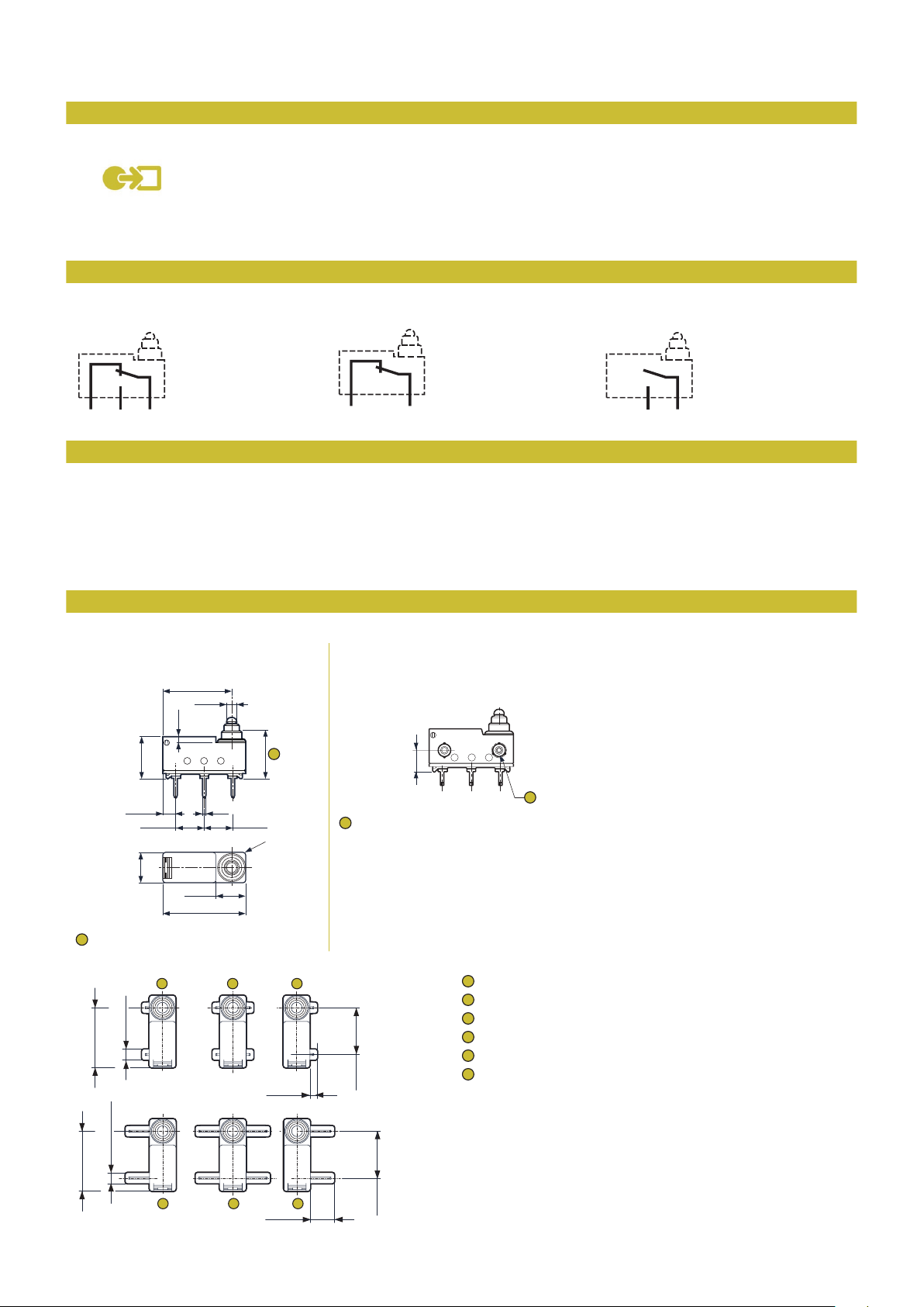
Dimensions
Products
8320
Version without locating pins
Total travel position: max 8.5
Locating pins
±0,08
Ø2,2
±0,1
12,13
12,13
±0,08
Ø2,2
456
8320
Version with locating pins
Ø 2.6 ±0.1 on ribs
2 short pins on rear (CAR)
4 short pins (4C)
2 short pins on front (CAV)
2 long pins on rear (LAR)
4 long pins (4L)
±0,1
1,5
±0,1
4,9
±0,15
9,53
±0,15
9,53
2 long pins on front (LAV)
Page 3

Recommendations for lateral approach
3,6
±0,2
0,5
±0,05
1
±0,2
1
2,05
±0,2
2,85
±0,2
0,5 0,6
±0,05±0,05
5,85
±0,2
2,05
±0,2
2,85
±0,2
0,5
±0,05
5,85
±0,2
0,6
±0,05
1
2,8
±0,2
2
±0,2
3,5
±0,2
0,5
±0,05
1
2,05
±0,2
0,1
±0,08
5,85
±0,2
2,05
±0,2
0,1
±0,08
5,85
±0,2
1
12,5
15,5
142
18
214
1
4
2
16
6,5
16
6,5
18
214
1
4
2
45° max.
35°
35°
35°
| MICROSWITCHES | 3 | SWITCHES.CROUZET.COM | 09/2020
In order to reduce friction and wear, the actuating ramp shall preferably be of
PA, POM, PBT or steel, and also be as smooth as possible.
As a general rule, the use of any lubricant substance is not needed nor
recommended.
For particular cases, please consult us.
45° 45°
35°
35°
35°
Connections
X1-X1L for printed circuit board,
straight output
X1 = 3.5 ± 0.2
X1L = 7 ± 0.2
W2 - W2ST solder CMS2 for surface mounting, rear output CMS3 for surface mounting, front output
X2 for printed circuit board, rear output X3 for printed circuit board, front output
With holes: W2 Ø 1.8 ± 0.1
Please contact us Please contact us
Without holes: W2ST
FB0 wire output on bottom FD0 wire output on right FG0 wire output on left
Wire characteristics
1: Black
2: Grey
4: Blue
Cross-section: 0.35 mm2
Standard length: 500 mm
Other lengths on request
(length in meters: e.g. 1.5)
Page 4

Drilling
5,08
±0,05
5,08
±0,05
3xØ1,3
+0,1
0
9,53
±0,05
5,85
±0,05
2,5
±0,05
5,08
±0,05
5,08
±0,05
9,86
±0,05
Ø2,5
±0,05
2,6
+0,1
0
3xØ1,3
+0,1
0
1
±
0.2
| MICROSWITCHES | 4 | SWITCHES.CROUZET.COM | 09/2020
Installation on printed circuit board
Installation on printed circuit board with locating pins
X1-X1L-X2-X3
Actuators
200AF flexible flat 200FF flexible dummy roller Other shapes and dimensions:
±0,1
R 3
F
±0,1
3,6
R0,7
2 14
1,25
R
±0,1
1,25
R
±0,1
±0,1
±0,2
8
F
0,3
±0,03
1
±0,1
3,6
R0,7
±0,2
±0,1
8
consult us
1
Operating position
Mounting accessories
Stainless steel mounting flange
±0.1
6,25
5.5
±0.1
22
0,3
±0.2
15,8
Ø 3,1
Page 5
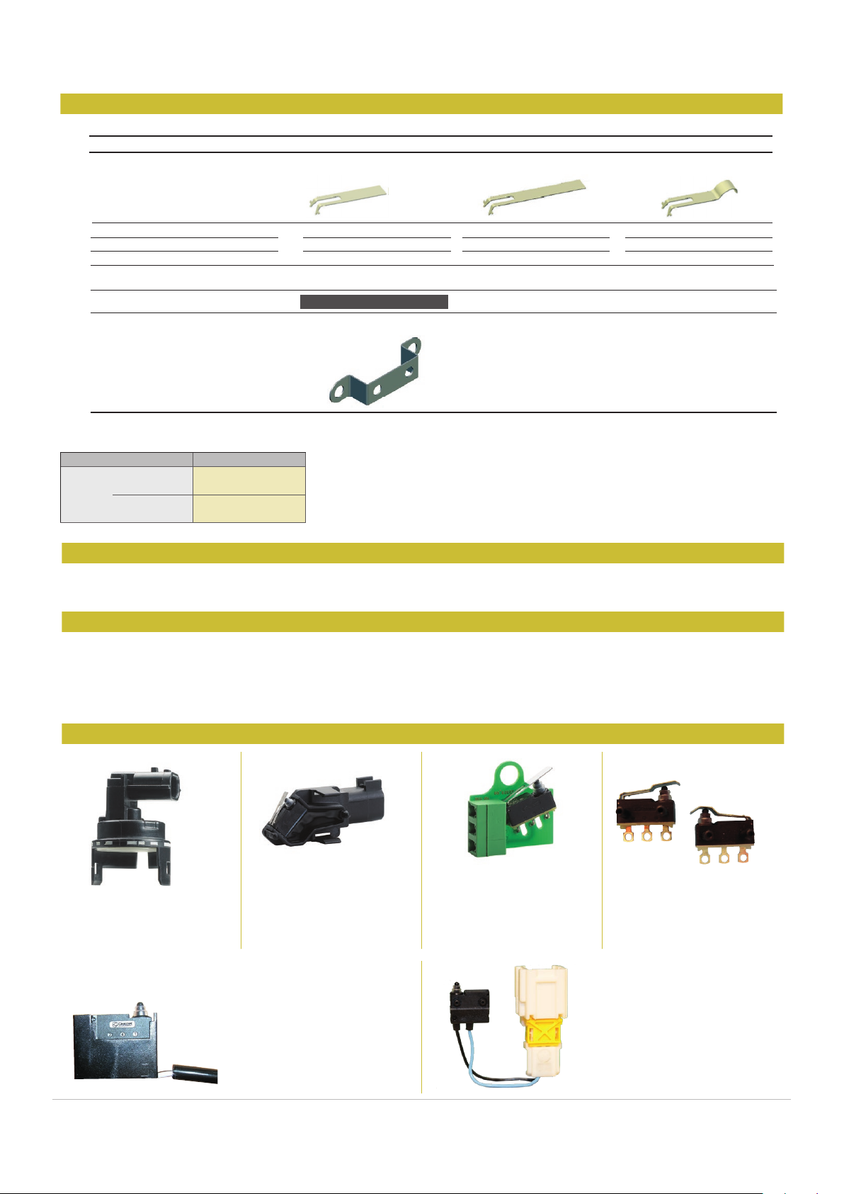
Flexibles actuators
Max. operating force (N)
Min. release force (N)
Operating position (mm)
Stainless steel mounting flange
Actuators are factory mounted
Actuators
1.5
0.1
11.4
±0.4
Flat 200AF R15
Flat 200AF R20
Dummy roller 200FF R17
1.3
0.05
12.2
±0.4
1.5
0.1
14.75
±0.5
79257491
Mounting accessories
Installation recommendations
How to order
Examples of special adaptations
Actuators and mounting accessories
V5S - 8320 microswitches with referenced actuators
| MICROSWITCHES | 5 | SWITCHES.CROUZET.COM | 09/2020
200AF R15
83200
Actuators
X1 83200229
X2 83200215
W2 LAR 83200223
FBO CAR 83200224
See “Basic technical concepts”
Use the 8 digit part numbers when they are dened
Other cases, precise: Type and Function - Connection - Locating pins - Actuator* - Adaptation* + Mounting accessories*
* if needed
Example: 83200 W2 CAV 200AF R15 + 79257491
IP67 module with 45° rotary
operation, maintained action,
integrated connector and quick
fastening
Warning:
The product information contained in this catalogue is given purely as information and does not constitute a representation, warrantly or any form of contractual commitment.
Crouzet Automatismes SAS and its subsidiaries reserve the right to modify their products without notice. It is imperative that we should be consulted over any particular use or application of our
products and it is the responsability of the buyer to establish, particularly through all the appropriate tests, that the product is suitable for the use or application. Under no circumstances will our warranty
apply, nor shall we be held responsible for any application (such as any modication, addition, deletion, use in conjunction with other electrical or electronic components, circuits or assemblies, or any
other unsuitable material or substance) which has not been expressly agreed by us prior to the sale of our products.
IP67 module with integrated
connector and quick fastening
“V4 size” conversion housing and
wire lead or cable output
Printed circuit board assembly
with connector
Special levers
Customized wiring
 Loading...