

Crouse Hinds 5F TAB/TAS UNIVERSAL SERIES Catalog Page
5F
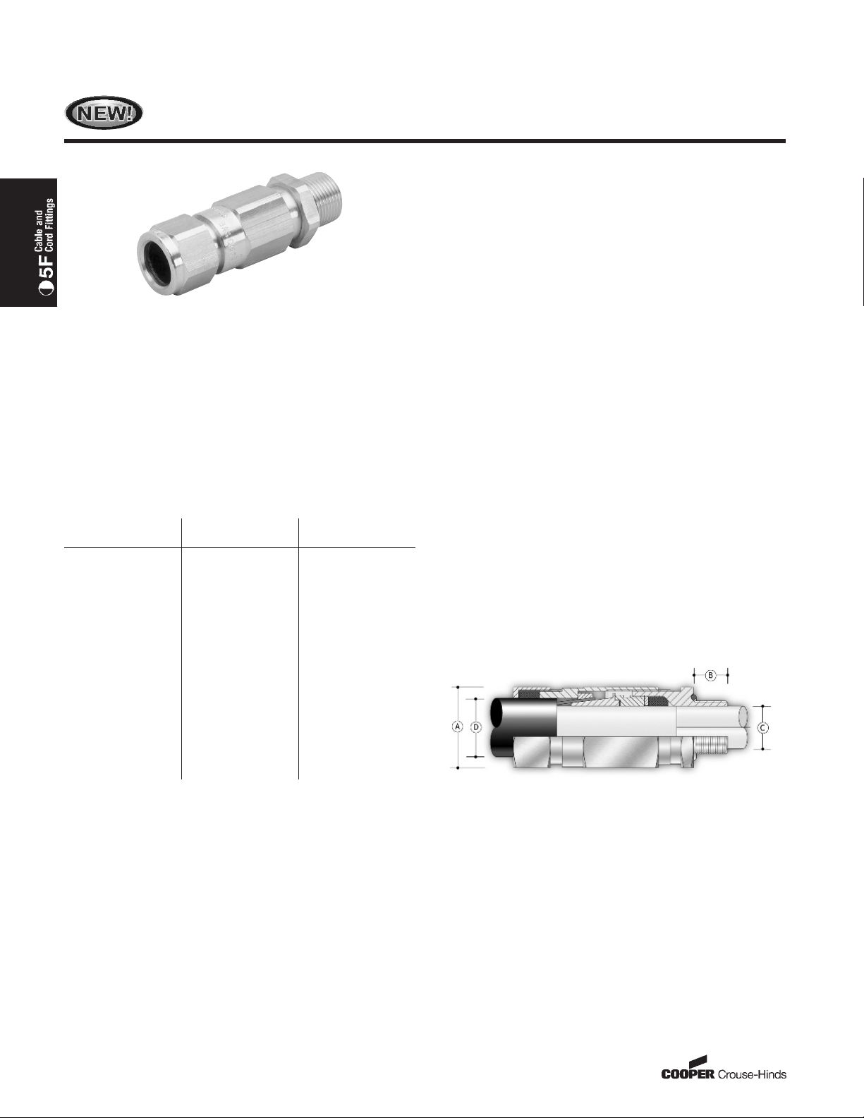
TAB/TAS UNIVERSAL SERIES
ATEX and CENELEC Range
Certifications and Compliances
ɀ ATEX E Exd IIC/E Exe II with SIRA 03ATEX2077X
ɀ Standards EN50014:1998, EN50018:2000,
EN50019:2000 and EN50281-1-1:1998
ɀ IP66 and IP68 at 25 meters
ɀ DTS011991 deluge
ɀ CSA Exd IIC/Exe II, Class I, Zone 1
ɀ Enclosure Type 4X
ɀ Zone 1 and Zone 2
ɀ Ignitible dusts, Zones 21 and 22
ɀ GOST R - Exd IICU/Exe IIU
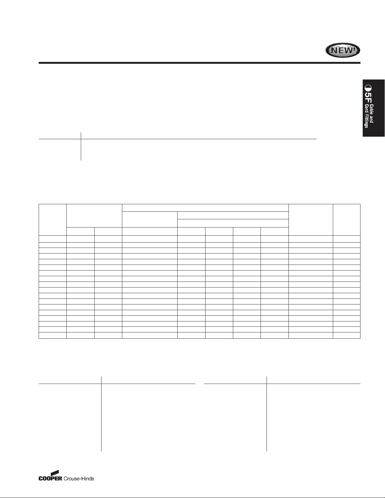
Design Data (millimeters)
Gland
Size
16 28.0 16
20S 28.0 16
20 33.0 16
25 41.4 16
32 50.6 16
40 60.5 16
50S 71.5 16
50 71.5 16
63S 88.0 19
63 88.0 19
75S 99.0 19
75 99.0 25
80 115.2 25
80H 115.2 25
85 115.2 25
90 125.7 25
90H 125.7 25
100 125.7 25
A
(across corners) B
ATEX and CENELEC Dual
E Exd IIC/E Exe II
CSA Exd IIC/Exe II
Class I, Zone 1
Zone 1 or 2 Hazardous Areas
IP66/68
Enclosure Type 4X
DTS01 1991 Deluge
Application
For use in Zone 1 or 2 hazardous areas with ATEX/CENELEC
equipment and wire, braided or tape armoured cables. For use in
Zone 1 or 2 hazardous areas with CSA equipment with braided and
marine shipboard cable.
Features
All TAB and TAS Cable glands:
ɀ offer a universal armour clamp for all armoured cable types (wire,
braided, tape, marine shipboard)
ɀ come with no reversible components, eliminating installer error
ɀ maintain Flameproof Exd and Increase Safety Exe methods of
explosion protection
ɀ provide a seal on the inner sheath
ɀ provide a seal on the outer sheath offering IP66/68 and Type 4X
protection
ɀ provide an O-Ring on the entry seal (metric entry threads only)
ɀ meet DTS011991 deluge requirements
ɀ are constructed of all brass or all stainless steel material
ɀ incorporate anti-twist assembly reducing the amount of cable twist
during installation
ɀ are available with metric or NPT threads
ɀ are available with optional nickel-plate finish
ɀ are available with optional silicone zero halogen seal for extreme
high and low temperature applications (-60°C to +180°C).
80 US: 1-866-764-5454 CAN: 1-800-265-0502 Copyright
©
2006 Cooper Crouse-Hinds
TAB/TAS Universal Series
Atex and CENELEC Range
ATEX and CENELEC Dual
E Exd IIC/E Exe II
CSA Exd IIC/Exe II
Class I, Zone 1
Zone 1 or 2 Hazardous Areas
IP66/68
Enclosure Type 4X
DTS01 1991 Deluge
Ordering Information
Build your catalog number from the information below. All catalog numbers consist of three main sections:
1. Select the Gland Type based on cable type and seal required (i.e., TAB1)
2. Select the Gland Size based on cable specifications (i.e., 20S)
3. Specify Thread Size (i.e., 075NPT) (Available sizes listed in step 2)
Step 1 – Select Gland Type from Table below:
Ordering example:
TAB1/20S/075NPT
Gland Types
Gland Type Description
TAB1 Universal gland for steel wire, steel braid & steel tape with neoprene seal - brass construction
TAB3 Universal gland for steel wire, steel braid & steel tape with silicone seal - brass construction
TAS1 Universal gland for steel wire, steel braid & steel tape with neoprene seal - stainless steel construction
TAS3 Universal gland for steel wire, steel braid & steel tape with silicone seal - stainless steel construction
For optional nickel-plate finish add suffix /NP after Gland Type (i.e., TAB1/NP).
For reduced bore gland add ‘‘R’’ at the end of gland type (i.e. TAB1R).
For optional poly-bagged kit including gland, locknut, earth tag, sealing washer and PVC shroud, add ‘‘K1’’ at the end of Gland Type (i.e., TAB1K1).
Step 2 – Select Gland Size based on Cable Size from Table below:
Cable Sizes
Gland
Size Metric NPT Min Max Min Max Min Max
16 M20
20S M20
20 M20
25 M25
32 M32 1⍯ or 11⁄4⍯ 19.5 26.3 26.7 34.0 23.2 30.5 0.15 - 2.00 EL46
40 M40 11⁄4⍯ or 11⁄2⍯ 23.0 32.2 33.0 40.6 28.6 36.2 0.20 - 2.00 EL55
50S M50 11⁄2⍯ or 2⍯ 28.1 38.2 39.4 46.7 34.8 42.4 0.30 - 2.50 EL65
50 M50 2⍯ 33.1 44.1 45.7 53.2 41.1 48.5 0.30 - 2.50 EL65
63S M63 2⍯ or 21⁄2⍯ 39.3 50.1 52.1 59.5 47.5 54.8 0.30 - 2.50 EL80
63 M63 21⁄2⍯ 46.7 56.0 58.4 65.8 53.8 61.2 0.30 - 2.50 EL80
75S M75 21⁄2⍯ or 3⍯ 52.3 62.0 64.8 72.2 60.2 68.0 0.30 - 2.50 EL90
75 M75 3⍯ 58.0 68.0 71.1 78.0 66.5 73.4 0.30 - 2.50 EL90
80 M80 x 2 3⍯ or 31⁄2⍯ 61.9 72.0 77.0 84.0 - - 0.45 - 3.15 L104
80H M80 x 2 3⍯ or 31⁄2⍯ 61.9 72.0 79.6 90.0 - - 0.45 - 3.15 L104
85 M85 x 2 3⍯ or 31⁄2⍯ 69.1 78.0 79.6 90.0 75.0 85.4 0.45 - 3.15 L104
90 M90 x 2 31⁄2⍯ or 4⍯ 74.1 84.0 88.0 96.0 - - 0.45 - 3.15 L114
90H M90 x 2 31⁄2⍯ or 4⍯ 74.1 84.0 92.0 102.0 - - 0.45 - 3.15 L114
100 M100 x 2 31⁄2⍯ or 4⍯ 81.8 90.0 92.0 102.0 87.4 97.4 0.45 - 3.15 L114
(Dimensions are all in millimeters)
Available
Entry Threads
1
⁄2⍯ or 3⁄4⍯ 3.4 8.4 9.0 13.5 6.7 10.3 0.15 - 1.25 L24
1
⁄2⍯ or 3⁄4⍯ 7.2 11.7 11.5 16.0 9.4 12.5 0.15 - 1.25 L24
1
⁄2⍯ or 3⁄4⍯ 9.4 14.0 15.5 21.1 12.0 17.6 0.15 - 1.25 EL30
3
⁄4⍯ or 1⍯ 13.5 20.0 20.3 27.4 16.8 23.9 0.15 - 1.60 EL38
Cable Inner
Sheath [C] Standard Reduced
GLAND SEAL RANGE
Cable Outer Sheath [D]
Armour
Acceptance
Range
5F
Shroud
Size
Step 3 – Specify Thread Size from Table below:
Metric Thread Sizes
Thread Size Add to Catalog Number
M16 M16
M20 M20
M25 M25
M32 M32
M40 M40
M50 M50
M63 M63
M75 M75
M80 M80
M85 M85
M90 M90
M100 M100
NPT Thread Sizes
Thread Size Add to Catalog Number
1
⁄2⍯ NPT 050NPT
3
⁄4⍯ NPT 075NPT
1⍯ NPT 100NPT
1
⁄4⍯ NPT 125NPT
1
1
⁄2⍯ NPT 150NPT
1
2⍯ NPT 200NPT
1
⁄2⍯ NPT 250NPT
2
3⍯ NPT 300NPT
1
⁄2⍯ NPT 350NPT
3
4⍯ NPT 400NPT
––
––
©
2006 Cooper Crouse-Hinds
81US: 1-866-764-5454 CAN: 1-800-265-0502 Copyright
 Loading...