

Page 1
Instruction Manual
MODEL 2083
TRANSLATOR
Model 2083-1721
Agile L to L Translator
August 2009 Rev A
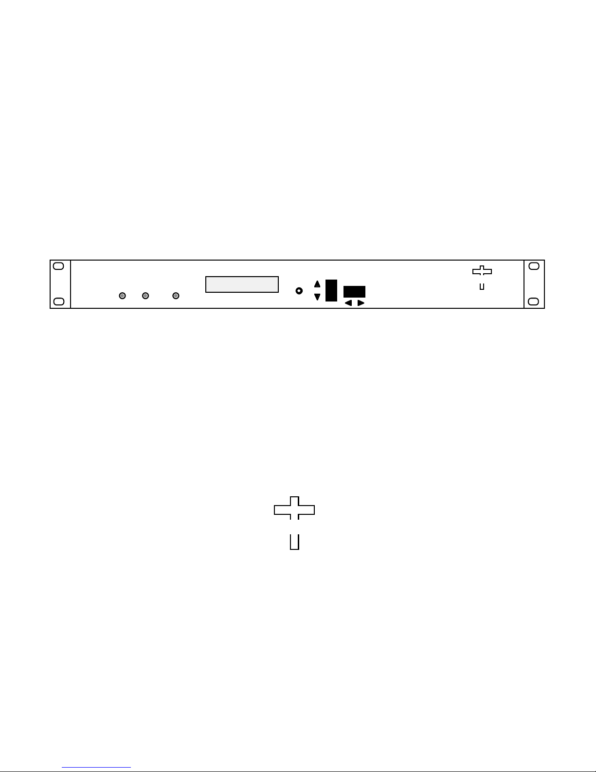
1350-1700>
1800-2150 G= 10
ALARMPOWERREMOTE
Data, drawings, and other material contained herein are proprietary to Cross Technologies, Inc.,
but may be reproduced or duplicated without the prior permission of Cross Technologies, Inc.
for purposes of operating the equipment. Printed in USA.
When ordering parts from Cross Technologies, Inc., be sure to include the equipment
model number, equipment serial number, and a description of the part.
MENU
EXECUTE
CROSS TECHNOLOGIES INC.
CROSS TECHNOLOGIES, INC.
6170 Shiloh Road
Alpharetta, Georgia 30005
(770) 886-8005
FAX (770) 886-7964
Toll Free 888-900-5588
WEB www.crosstechnologies.com
E-MAIL [email protected]
Page 2

INSTRUCTION MANUAL
MODEL 2083-1721 Translator
TABLE OF CONTENTS PAGE
Warranty 2
1.0 General 3
1.1 Equipment Description 3
1.2 Technical Characteristics 4
1.3 Monitor & Control Interface 5
2.0 Installation 7
2.1 Mechanical 7
2.2 Rear I/O’s 8
2.3 Front Panel Controls, Indicators 8
2.4 Operation 9
2.5 Menu Settings 10
3.0 Environmental Use Information 15
WARRANTY - The following warranty applies to all Cross Technologies, Inc. products.
All Cross Technologies, Inc. products are warranted against defective materials and
workmanship for a period of one year after shipment to customer. Cross Technologies,
Inc.’s obligation under this warranty is limited to repairing or, at Cross Technologies, Inc.’s
option, replacing parts, subassemblies, or entire assemblies. Cross Technologies, Inc. shall
not be liable for any special, indirect, or consequential damages. This wa rranty does not
cover parts or equipment which have been subject to misuse, negligence, or accident by the
customer during use. All shipping costs for warranty repairs will be prepaid by the
customer. There are not other warranties, express or implied, except as stated herein.
CROSS TECHNOLOGIES, INC.
6170 Shiloh Road
Alpharetta, Georgia 30005
(770) 886-8005
FAX (770) 886-7964
Toll Free 888-900-5588
2083-1721 Manual, Rev.A Page 2 8/27/09
WEB www.crosstechnologies.com
E-MAIL [email protected]
Page 3
MODEL 2083-1721 Agile L to L Translator
MODEL 2083
TRANSLATOR
1.0 General
1.1 Equipment Description
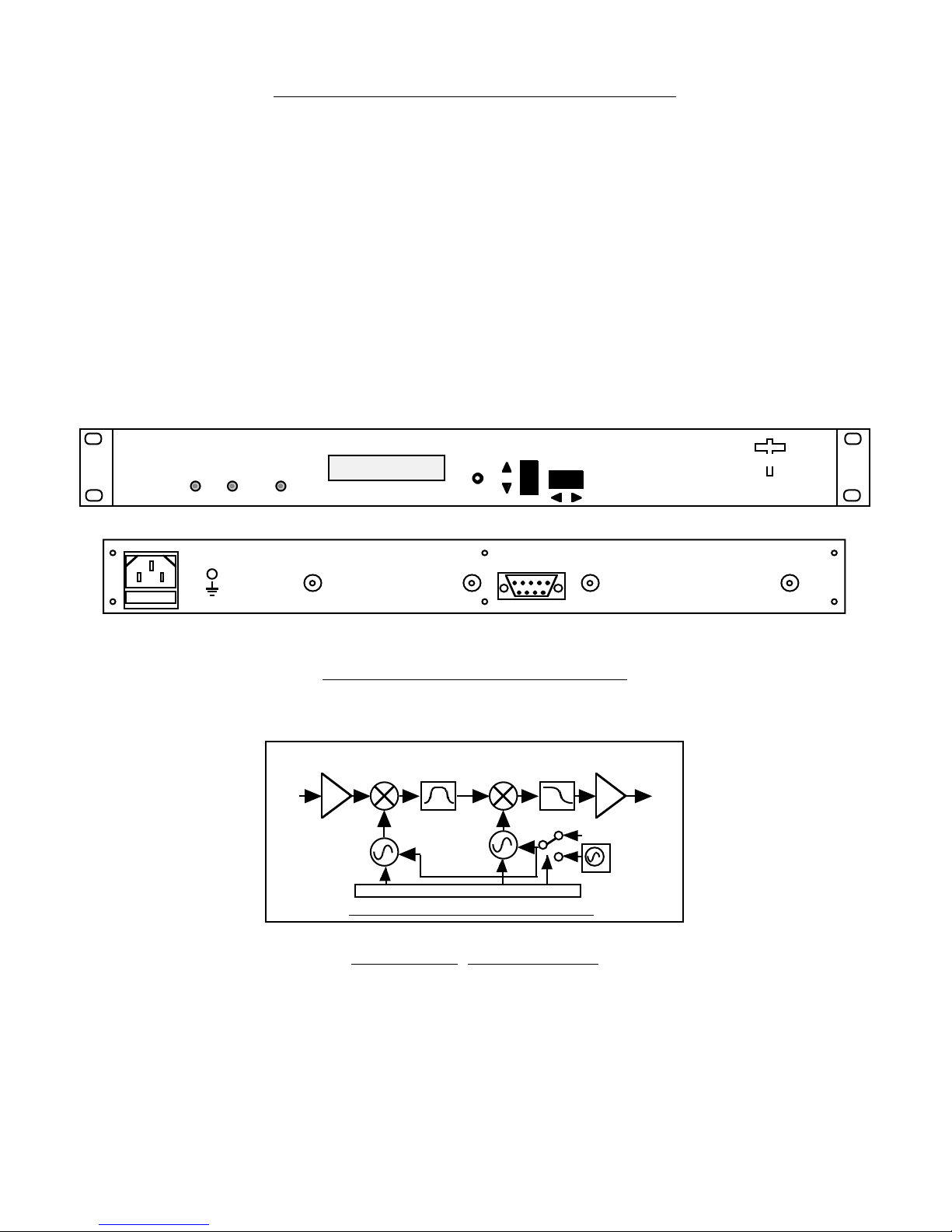
The 2083-1721 Agile L to L Translator converts a 1350-1700 MHz block to 1800-2150 MHz block with no
spectrum inversion, low group delay and flat frequency response. The 1350-1700 MHz input is mixed with
synthesized local oscillator (LO) signals, first to 3100 MHz center frequency and finally to the 1800-2150 MHz
block output. Multi-function push button switches select the input level and gain. Frequency translation and
gain (0 to +20 dB, selectable in 1 dB steps) settings appear on the LCD display. Front panel LEDs light when
DC power is applied (green) or a PLL alarm occurs (red). Connectors are BNC female for R F input and output
and for (optional) external 10 MHz reference (+3± 3 dBm in). The 2083-1721 is housed in an 1 3/4” X 19” X
16” deep rack mount chassis. Option -H provides a 0.01 ppm reference.
1350-1700>
1800-2150 G= 10
ALARMPOWERREMOTE
MENU
EXECUTE
CROSS TECHNOLOGIES INC.
FRONT PANEL
AC
GND
RF IN
J2 J5J3J18
10 MHZ REF
OUTPUT INPUT
MONITOR
AND
CONTROL
J10
10 MHZ
EXT REF
15 234
6789
RF OUT
REAR PANEL
FIGURE 1.1 Front and Rear Panels
1350 1700
MHz
IN
2900-3250
MHz BP
4600
MHz
CONTROLLER
5050
MHz
2083-1721 Translator Block Diagram
2200 MHz
LP Filter
**EXT
10 M
I**NT/EXT
18002150MHz
Out
I**OPTIONAL
2083-1721 Manual, Rev.A Page 3 8/27/09
FIGURE 1.2 Block Diagram
Page 4
1.2 Technical Characteristics
q
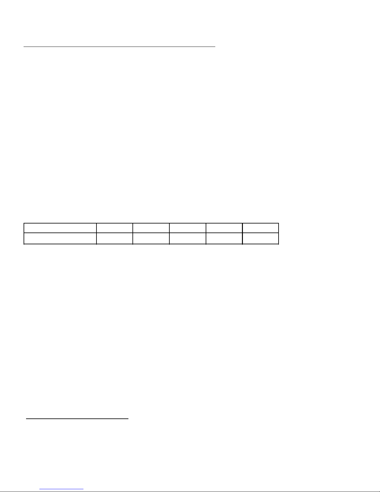
TABLE 1.0 2083-1721 Frequency Translator Specifications*
Input Characteristics
Input Impedance/RL 75 /12 dB
Frequency, 1350-1700 MHz
Input Level -10 to -30 dBm
Input 1 dB compression 0 dBm
Output Characteristics
Impedance/RL 75 /12 dB
Output Level, Range -10 to -30 dBm
Output 1 dB compression 0 dBm
Frequency 1800-2150 MHz
Channel Characteristics
Gain 0 to +20 ± 1 dB, selectable in 1 dB steps
Frequency Response ± 1.0 dB, 350 MHz bandwidth; ± 0.5 dB, any 36 MHz increment
Spurious Response <-45 dBC in band; <-50 dBm out of band
Group Delay, max 0.01 ns/MHz2, parabolic, 0.03ns/MHz, linear, 1 ns ripple any 36 MHz BW
Frequency Sense Non-Inverting
Synthesizer Characteristics
Frequency Accuracy ± 1 ppm max over temp: Optional, High Stability (± 0.01 ppm) Option -H
Reference 10 MHz Internal;Internal/External selectable is Option -E
Phase Noise @ Fre
dBC/Hz
1MHz100kHz10kHz1kHz100 Hz
-100-90-80-70-65
Controls, Indicators
Frequency Translation Setting shown on LCD display
Input Level Selection Pushbutton switches; setting shown on LCD display;
Set to composite input level
Gain Selection Pushbutton switches; setting shown on LCD display;
Set to 0 to +20 dB (-10 dBm max out)
DC Power; PLL Alarm Green LED; Red LED
Other
Connectors RF In and Out and (optional) external 10 MHz ref. In, BNC, female,75 ohm
Connector, Alarm DB9 - NO or NC contact closure on Alarm
Size 19 inch standard chassis 1.75” high X 16.0” deep
Power 100-240 (±10%) VAC, 47-63 Hz, 30 watts max.
Options
-E External 10 MHz reference In
- D BNC, female, 50 ohms for RF In and Out
- H High Stability (± 0.01 ppm) internal reference
Connector options see TABLE 2.2
*+10˚C to +40˚C; Specifications subject to change without notice
2083-1721 Manual, Rev.A Page 4 8/27/09
Page 5
1.3 Monitor and Control Interface
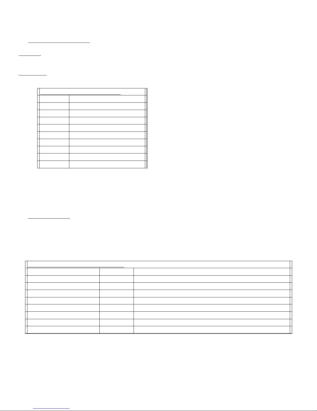
J10 Pinouts
Pin Function
* PLEASE NOTE: The two character {aa}(00-31) prefix, in the table below,
should be used ONLY when R
S-485, (OPTION-Q), is selected.
TABLE 1.1 2083-1721 Statuss
TABLE 1.1 2083-1721 Status Requests
Command Syntax * Description
(option E only)
A) Remote serial interface
Protocol: RS-232C, 9600 baud rate, no parity, 8 data bits, 1 start bit, and 1 stop bit.
(RS-232C, RS-422, or RS-485 - option Q)
Connector: Rear panel, DB-9 male
1Rx2 Rx+ (RS-232C)
3 Tx+ (RS-232C)
4Tx5GND
6 Alarm Relay: Common
7 Alarm Relay: Normally Open
8Not Used
9 Alarm Relay: Normally Closed
B) Status Requests - Table 1.1 lists the status requests for the 2083-1721 and briefly describes them.
Command Status {aaS1} Returns {aaS1bbA} where:
10 MHz Reference Status {aaS2} Returns {aaS2ER} where:
• bb = Gain in dB
• A = 0 - summary alarm
• E = Ext 10MHz Status (1 = on, 0 = off)
• R = 10MHz RF insertion status (1 = inserted, 0 = NOT inserted)
2083-1721 Manual, Rev.A Page 5 8/27/09
Page 6

C) Commands
* PLEASE NOTE: The two character {aa}(00-31) prefix, in the table below,
should be used ONLY when R
S-485, (OPTION-Q), is selected.
Table 1.2 2083-1721 Commaands
Command Syntax* Description
(option -E only)
(option -E only)
Table 1.2 lists the commands for the 2083-1721 and briefly describes them. A fter a command is sent the 2083
sends a return “>” indicating the command has been received and executed.
General Command Format - The general command format is {CND...}, where:
{ = start byte
C = 1 character, either C (command) or S (status)
N = 1 character command or status request
D = 1 character or more of data (depends on command)
} = stop byte
Set Frequency Band
Set Input Level
Set Gain {aaC3xx}
Enable 10MHz RF Insertion {aaC5x} where x = :
Enable External 10MHz {aaCEx} where x = :
Enable Remote # Just # sign
Disable Remote {aaCR0} {CR and zero}
• xx = 2 characters
• Range: 00 to 20 (0 dB to 20 dB, in 1 dB steps)
• 0 to disable 10MHz RF insertion
• 1 to enable 10MHz RF insertion
• 0 to disable External 10MHz ref signal
• 1 to enable External 10MHz ref signal
2083-1721 Manual, Rev.A Page 6 8/27/09
Page 7
2.0 Installation
2.1 Mechanical
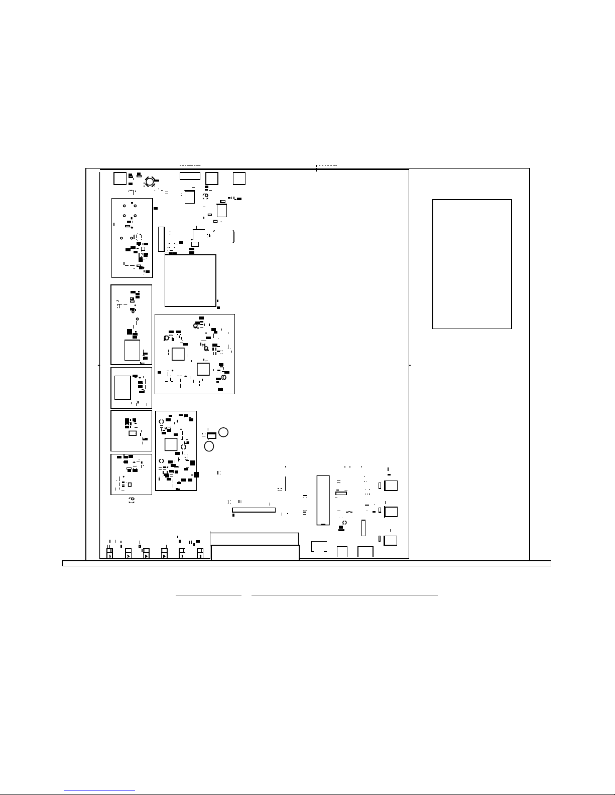
The 2083-1721 consists of one RF/Controller PCB housed in a 1 RU (1 3/4 inch high) by 16 inch deep chassis.
A switching, ± 12, +24, +5 VDC power supply provides power for the assemblies. The 2083-1721 can be
secured to a rack using the 4 holes on the front panel. Figure 2.0 shows how the 2083-1721 is assembled.
POWER
SUPPLY
FIGURE 2.0 2083-1721 Mechanical Assembly
2083-1721 Manual, Rev.A Page 7 8/27/09
Page 8
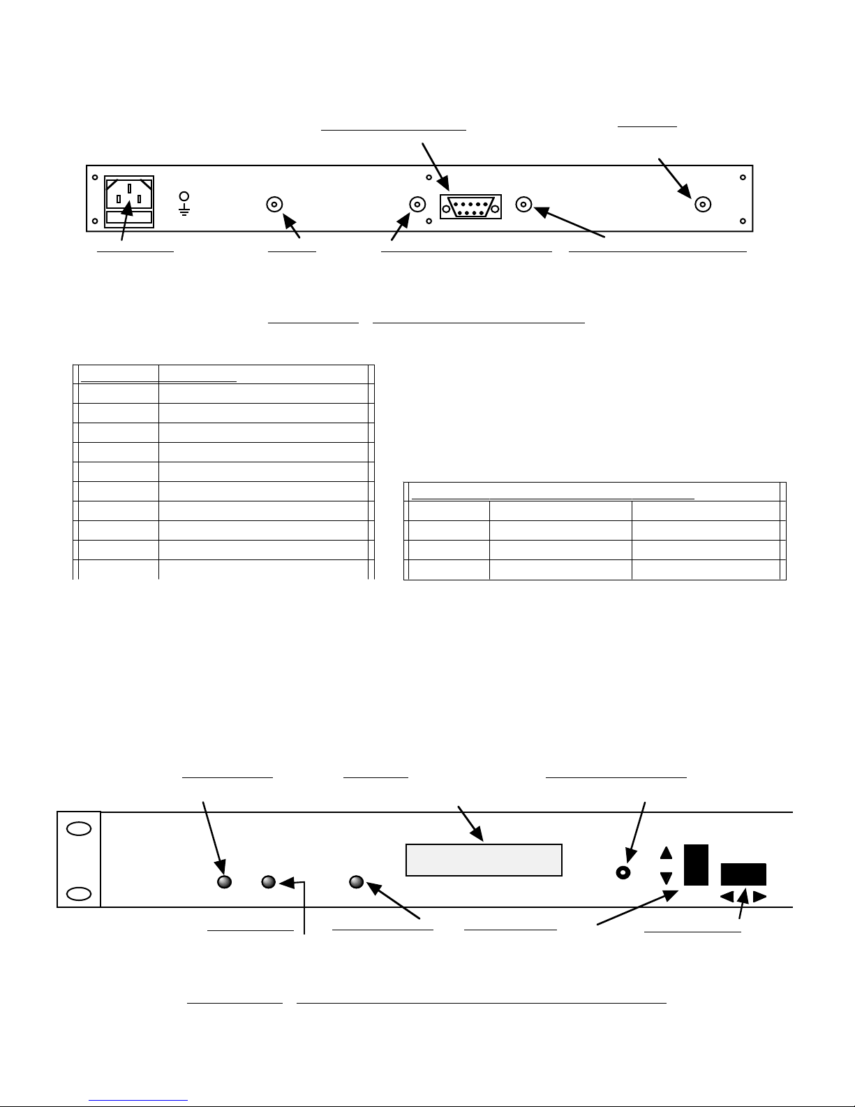
2.2 Rear Panel Input/Output Signals
TABLE 2.1 JJ10
TABLE 2.1 J10 Pinouts*
Pin Function
TABLE 2.2 IInput/Output
Option Input Output
Figure 2.1 shows the input and output connectors on the rear panel.
AC
GND
AC1 - POWER IN
AC input for switching
power supply.
100-240 ±10% VAC,
47-60 Hz.
RF IN
J2 J5J3J18
J2 - INPUT
1350-1700 MHz,
-10 to -30 dBm input
see Table 2.2.
FIGURE 2.1 2083-1721 Rear Panel I/Os
1Rx2 Rx+ (RS-232C)
3 Tx+ (RS-232C)
4Tx5GND
6 Alarm Relay: Common
7 Alarm Relay: Normally Open
8Not Used
9 Alarm Relay: Normally Closed
*Remote Serial Interface
Interface: DB-9 Male
Protocol: RS-232C (RS-232C/422/485,
option Q), 9600 baud rate, no parity, 8 data
bits, 1 start bit, 1 stop bit.
J10 - MONITOR AND CONTROL
DB9 female connector. see Table 2.1.
MONITOR
10 MHZ REF
OUTPUT INPUT
J18 - 10 MHz REF OUTPUT (option E)
10 MHz reference output.
75 BNC female connector.
AND
CONTROL
J10
STD BNC, 75 BNC, 75
DBNC, 50 BNC, 50
F Type F, 75 Type F, 75
J5 - OUTPUT
1800-2150 MHz,
-10 to -30 dBm output
see Table 2.2.
10 MHZ
EXT REF
15 234
6789
J3 - 10 MHz EXT REF INPUT (Option E)
10 MHz external reference input, 3 ± 3 dBm,
75 ohms, BNC female connector.
RF OUT
2.3 Front Panel Controls and Indicators
Figure 2.2 shows the front panel controls and indicators.
DS1 - REMOTE LED
Yellow LED indicates
remote operation.
REMOTE POWER
DS6 - POWER LED
Green LED indicates
presence of DC power.
FIGURE 2.2 2083-1721 Front Panel Controls and Indicators
2083-1721 Manual, Rev.A Page 8 8/27/09
LCD DISPLAY
Display shows frequency in MHz,
Gain in dB, and Input Level in dBm
1350-1700>
1800-2150 G=+10
ALARM
DS2 - UP ALARM LED
Red LED indicates
upconverter alarm.
S1 - MENU/EXECUTE BUTTON
Press this to get into Program mode
and to execute any changes.
MENU
EXECUTE
S2 - VERT. TOGGLE
Vertical toggle switch that controls
values in the Menu items when in
program mode. Does not function in the
normal display mode
S3 - HORIZ. TOGGLE
Horizontal toggle switch that
controls which values are being
adjusted. Does not function in the
normal display mode
Page 9
2.4 Installation / Operation
2.4.1 Installing and Operating the 2083-1721, Frequency Translator Section
1. Connect a -10 dBm to -30 dBm signal to IN, J4 (Figure 2.1)
2. Connect the OUT, J5, to the external equipment
3. Connect 100-240 ±10% VAC, 47 - 63 Hz to AC connector on the back panel.
4. Set the desired output frequency band (See Section 2.5 Menu Settings).
5. Set the composite input level (See Section 2.5 Menu Settings).
6. Set the gain for 0 to +20 dB. Make sure the output stays within -10 to -30 dBm with the gain selected
and the input level provided. The firmware will prevent setting gain and input level outside this range.
(See Section 2.5 Menu Settings).
7. Be sure DS6 (green, DC Power) is on and DS2 (red, Alarm) is off (Figure 2.2).
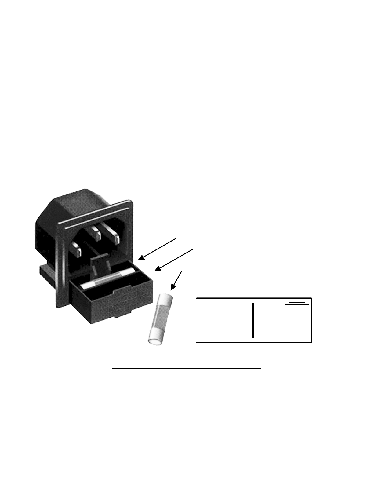
8. AC Fuse - The fuse is a 5 mm X 20 mm, 2 amp slow blow (Type T) and is inserted in the far slot in the
drawer below the AC input as shown in Figure 2.3. There is a spare fuse in the near slot.
If a fuse continues to open, the power supply is most likely defective.
FUSE DRAWER
SPARE FUSE DRAWER
AC Fuse - 2 amp slow blow (Type T 2A GDC),
5 mm X 20 mm
INPUT
~
100-240± 10%VAC
47-63 Hz
2A MAX
FIGURE 2.3 Fuse Location and Spare Fuse
~
FUSE
TYPE T 2A GDC
250 VOLT
FOR 100 - 240 V~
2083-1721 Manual, Rev.A Page 9 8/27/09
Page 10

2.5 Menu Settings
2.5.1 Functions
This section describes operation of the front panel controls. There are three ope rator switches, the LCD display
and alarm indicator LEDs. All functions for the equipment are controlled by these components. The functions
are (see Figure 2.4):
Power Up
Normal Display
Menu 1 Gain (0 to +20, 1dB steps)
Menu 2 Set Unit to Remote Operation
Menu 3 Select External 10 MHz Ref (option -E)
Menu 4 Select 10 MHz Reference RF insertion (option -E)
Menu 5 Set Remote mode (option -Q)
Menu 6 Set RS-485 address (option -Q)
Save Menu When “R” is selected in any above menu, or when the end is reached (after Menu 8)
Alarm indications appear on the LEDs (see Figure 2.2).
All program changes must start with the operation of the Menu/Execute switch and must also end with the
operation of the Menu/Execute switch verified by the “Save Settings?” Menu. If this sequence is not followed,
none of the changes will take effect. If programming is initiated and no operator action takes place for
approximately 12 seconds (before the final press of the Menu/Execute switch) the display will revert to its
previous status and you will need to start over.
2083-1721 Manual, Rev.A Page 10 8/27/09
Page 11
2.5.2. Power On Settings
REV 1.00
1350-1700>
1800-2150 G=+00
NOTE: THE LAST STATUS OF A UNIT IS RETAINED EVEN WHEN POWER IS REMOVED.
WHEN POWER IS RESTORED, THE UNIT WILL RETURN TO IT'S PREVIOUS SETTINGS.
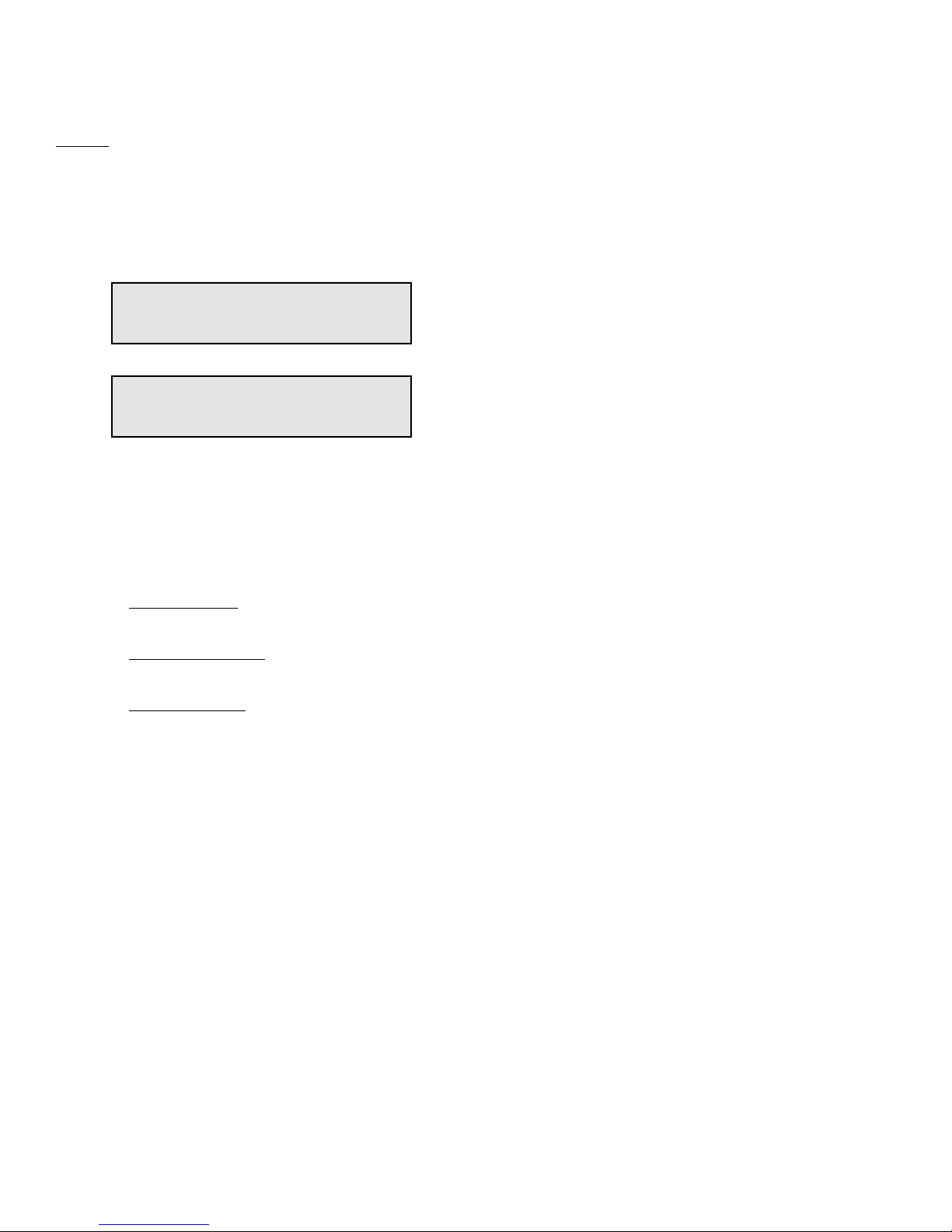
When power is first applied, the LCD display goes through three steps.
1. The LCD goes black to show all segments are functioning.
2. The software version will be displayed.
3. The present frequency and gain of the upconverter is shown.
The unit is now operational and ready for any changes the operator may desire.
2.5.3 Control Switches
1. Menu/Execute - Any change to the programming of the unit must be initiated by pressing the
Menu/Execute switch and completed by pressing the Menu/Execute switch.
2. Horizontal Switch - This switch is mounted so its movement is horizontal and moves the cursor
left or right.
3. Vertical Switch - This switch is mounted so its movement is vertical and has two functions:
a. During frequency , gain changes, the vertical movement will raise or lower the number
in the direction of the arrows.
b. For other functions such Remote on/off, the vertical switch will alternately turn the function
on or off regardless of the direction operated.
2083-1721 Manual, Rev.A Page 11 8/27/09
Page 12
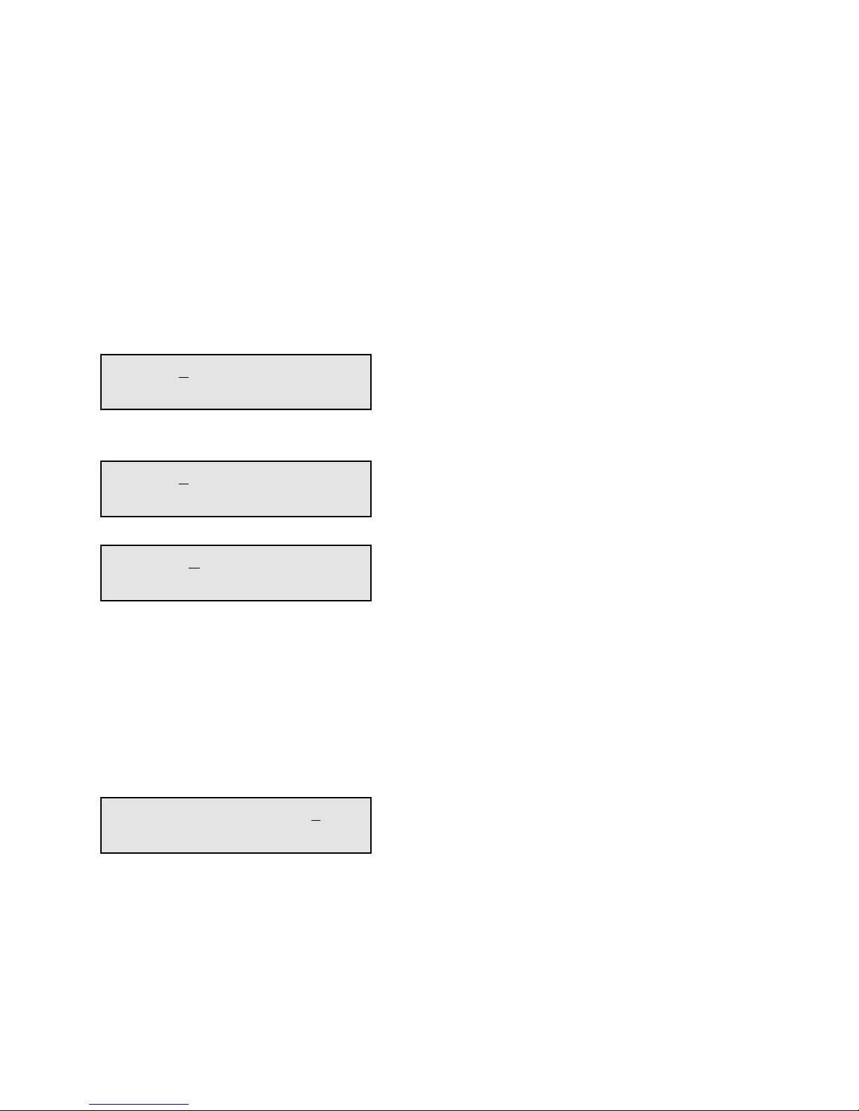
2.5.4 Gain Changes
UP G= +00
R
UP G= +10
R
UP G= +10
R
SAVE SETTINGS?
Y N
When you get to this menu note that the gain changes will be made as you make them but if you do not wish to
save the changes you have made, scroll to “R” and push the menu/Execute switch and select “NO” in the
“SAVE SETTINGS?” window or do not press the Menu/Execute switch; simply do nothing for
approximately 12 seconds, and the system will return to the normal operating mode.
NOTE: CHANGES TAKE PLACE ON LEVEL AND GAIN IMMEDIATELY BUT DO NOT GET
SAVED UNTIL YOU GO TO THE SAVE MENU AND INDICATE YOU WANT TO SAVE THE
CHANGES.
Press the Up/Down switch to change the level in 1 dB steps and then push the Menu/Execute switch to
get to the Gain setting:
Pressing the Up/Down switch to change the ga in in 1 or 10 dB steps and then pus h the Menu/Execute
switch to get to the Gain setting:
By using the horizontal rocker switch the cursor can be moved left or right.
Pressing the Up/Down switch down will toggle the display digit selected until you have the desired gain.
NOTE: THE GAIN WILL BE CHANGED AS YOU ADJUST THE NUMBERS. HOWEVER, THE
VALUE WILL NOT BE STORED UNTIL YOU INDICATE YES IN THE SAVE SETTINGS
WINDOW. DO NOT SET A GAIN THAT WOULD EXCEED 0 dBm OR HAVE LESS THAN -30 dBm
OUTPUT LEVEL. THE FIRMWARE PREVENTS YOU FROM THIS.
When the display indicates the value desired you can push the Menu/Execute switch to the next item OR
you can scroll to “R”, push the Menu/Execute switch to get to:
Selecting Y will save the new settings. Selecting N will revert to the previous settings.
Figure 2.4 gives the menu items and how to make changes
2083-1721 Manual, Rev.A Page 12 8/27/09
Page 13
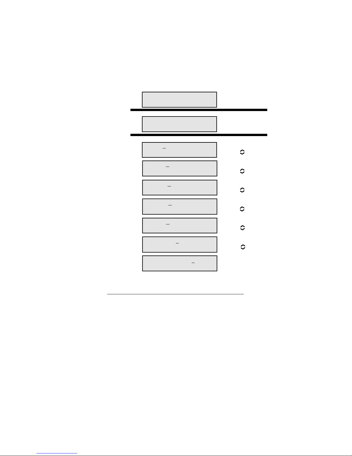
2.5.5 Alarm Indications
ON POWER UP
NORMAL DISPLAY
PUSHING MENU/EXECUTE SEQUENCE
REV 1.00
1350-1700>
1800-2150 G=+00
REMOTE OFF
EXT REF OFF
SCROLL <>
SCROLL
UP G= +00
SCROLL <>
SCROLL
SCROLL <>
SCROLL
SAVE SETTINGS? Y N
SCROLL <>
R
R
R
REF OUT OFF
SCROLL <>
SCROLL
R
RS 485 OFF
SCROLL <>
SCROLL
R
ADDRESS = 00
SCROLL <>
SCROLL
R
An alarm condition for will occur if any local oscillator phase lock loop (PLL) comes out of lock.
The Mute LED will light if you select Mute and the Remote LED will light when you select the Remote mode.
Power Up
Normal Display
PUSH BUTTON
Menu 1 Gain (0 to +20)
PUSH BUTTON
Menu 2 Set Unit to Remote
Operation
Menu 3 Select External 10 MHz
Reference (option -E)
PUSH BUTTON
PUSH BUTTON
Menu 4 Select 10MHz Reference
RF Insertion (option -E)
Menu 5 Set Remote Mode
(option -Q)
Menu 6 Set RS-485 Address
(option -Q)
Save? When go to end
FIGURE 2.4 Menu Display and Sequences
PUSH BUTTON
PUSH BUTTON
PUSH BUTTON
PUSH BUTTON
2083-1721 Manual, Rev.A Page 13 8/27/09
Page 14

3.0 Environmental Use Information
A. Rack-Mounting - To mount this equipment in a rack, please refer to the installation instructions
located in the user manual furnished by the manufacturer of your equipment rack.
B. Mechanical loading - Mounting of equipment in a rack should be such that a hazardous condition
does not exist due to uneven weight distribution.
C. Elevated operating ambient temperature - If installed in a closed or multi-unit rack assembly,
the operating ambient temperature of the rack may be greater than room ambient temperature.
Therefore, consideration should be given to Tmra.
D. Reduced air flow - Installation of the equipment in a rack should be such that the amount of air flow
required for safe operation of the equipment is not compromised. Additional space between unit
may be required.
E. Circuit Overloading - Consideration should be given to the connection of the equipment to the supply
circuit and the effect that overloading of circuits could have on over current protection and supply wiring.
Appropriate consideration of equipment name plate rating should be used, when addressing this concern.
F. Reliable Earthing - Reliable earthing of rack-mounted equipment should be maintained. Particular
attention should be given to supply connections other than direct connection to the Branch
(use of power strips).
G. Top Cover - There are no serviceable parts inside the product so, the Top Cover should not be removed.
If the Top Cover is removed the ground strap and associated screw MUST BE REINSTALLED
prior to Top Cover screw replacement. FAILURE TO DO this may cause INGRESS and/or EGRESS
emission problems.
2083-1721 Manual, Rev.A Page 14 8/27/09
Page 15

CROSS TECHNOLOGIES, INC.
6170 Shiloh Road
Alpharetta, Georgia 30005
(770) 886-8005
FAX (770) 886-7964
Toll Free 888-900-5588
WEB www.crosstechnologies.com
E-MAIL [email protected]
2009 • Printed in USA
2083-1721 Manual, Rev.A Page 15 8/27/09
 Loading...