

Cross Technologies 1582-650 Instruction Manual
Instruction Manual
Model 1582-650
RF Switch
January 2011 Rev C
ALARM
HISTORY
STATUS
21
HISTORY
RESET
POWER
MODEL 1582
21
SWITCH
CROSS TECHNOLOGIES INC.
SWITCH
AUTO
CH1
CH1
ONLINE
MANUAL
SELECT
CH2
CH2
ONLINE
RESET
MANUAL REMOTESWITCH
21
ALARM
Data, drawings, and other material contained herein are proprietary to Cross Technologies, Inc.,
but may be reproduced or duplicated without the prior permission of Cross Technologies, Inc.
for purposes of operating the equipment. Printed in USA.
When ordering parts from Cross Technologies, Inc., be sure to include the equipment
model number, equipment serial number, and a description of the part.
CROSS TECHNOLOGIES, INC.
6170 Shiloh Road
Alpharetta, Georgia 30005
(770) 886-8005
FAX (770) 886-7964
Toll Free 888-900-5588
WEB: www.crosstechnologies.com
E-MAIL: info@crosstechnologies.com

INSTRUCTION MANUAL
MODEL 1582-650 RF Switch
TABLE OF CONTENTS PAGE
Warranty 2
1.0 General 3
1.1 Equipment Description 3
1.2 Technical Characteristics 4
2.0 Installation 5
2.1 Mechanical 5
2.2 Input and Output Signals 6
2.3 Controls and Indicators 6
2.4 Operation 8
2.5 Switch Mode Setup 9
3.0 Environmental Use Information 10
WARRANTY - The following warranty applies to all Cross Technologies, Inc. products.
All Cross Technologies, Inc. products are warranted against defective materials and
workmanship for a period of one year after shipment to customer. Cross Technologies,
Inc.’s obligation under this warranty is limited to repairing or, at Cross Technologies, Inc.’s
option, replacing parts, subassemblies, or entire assemblies. Cross Technologies, Inc. shall
not be liable for any special, indirect, or consequential damages. This warranty does not
cover parts or equipment which have been subject to misuse, negligence, or accident by the
customer during use. All shipping costs for warranty repairs will be prepaid by the
customer. There are not other warranties, express or implied, except as stated herein.
1582-650 Manual, Rev. C Page 2 01/26/10
CROSS TECHNOLOGIES, INC.
6170 Shiloh Road
Alpharetta, Georgia 30005
(770) 886-8005
FAX (770) 886-7964
Toll Free 888-900-5588
WEB: www.crosstechnologies.com
E-MAIL: info@crosstechnologies.com
MODEL 1582-650 RF Switch
1.0 General
1.1 Equipment Description
The 1582-650 RF Switch provides Auto, Manual or Remote relay switching between CH1 and CH2 RF signals.
Alarm conditions on CH1 and CH2 are either a contact closure to ground or an open (selectable). The logic
controls one single pole, double throw RF switch. Switching logic can be selected as follows:
1. CH1 Prime Mode - Switches from CH1 to the CH2 only if CH1 alarms and CH2 is good. Switches back
when CH1 no longer in alarm or both CH1 and CH2 are bad.
2. Latch to CH2 Mode - Switches to CH2 if CH1 alarms and CH2 is good. Latches to CH2. Push Manual
Reset or ground Remote Reset pin to return to CH1 if it has no alarm.
3. Minimum AUTO switching, Initial Channel Select (ICS) Mode - Switch stays on channel last selected by
Manual or Remote selection after return to AUTO. AUTO switching occurs only if current channel
alarms and other channel clear.
When power is lost, channel one is selected. The Manual Select switch and (when in AUTO) contact closures to
Remote Select pins, select CH1 or CH2 independent of alarms. LEDs indicate alarm and switch conditions for
CH1 and CH2 and REMOTE or MANUAL operation. Redundant power supplies provided.
CH1
ONLINE
AC1
CH1
AUTO
MANUAL
SELECT
SWITCH
CH2
ONLINE
CH2
AC2
RESET
STATUS
21
MANUAL REMOTESWITCH
ALARM
ALARM
HISTORY
21
HISTORY
RESET
21
POWER
MODEL 1582
SWITCH
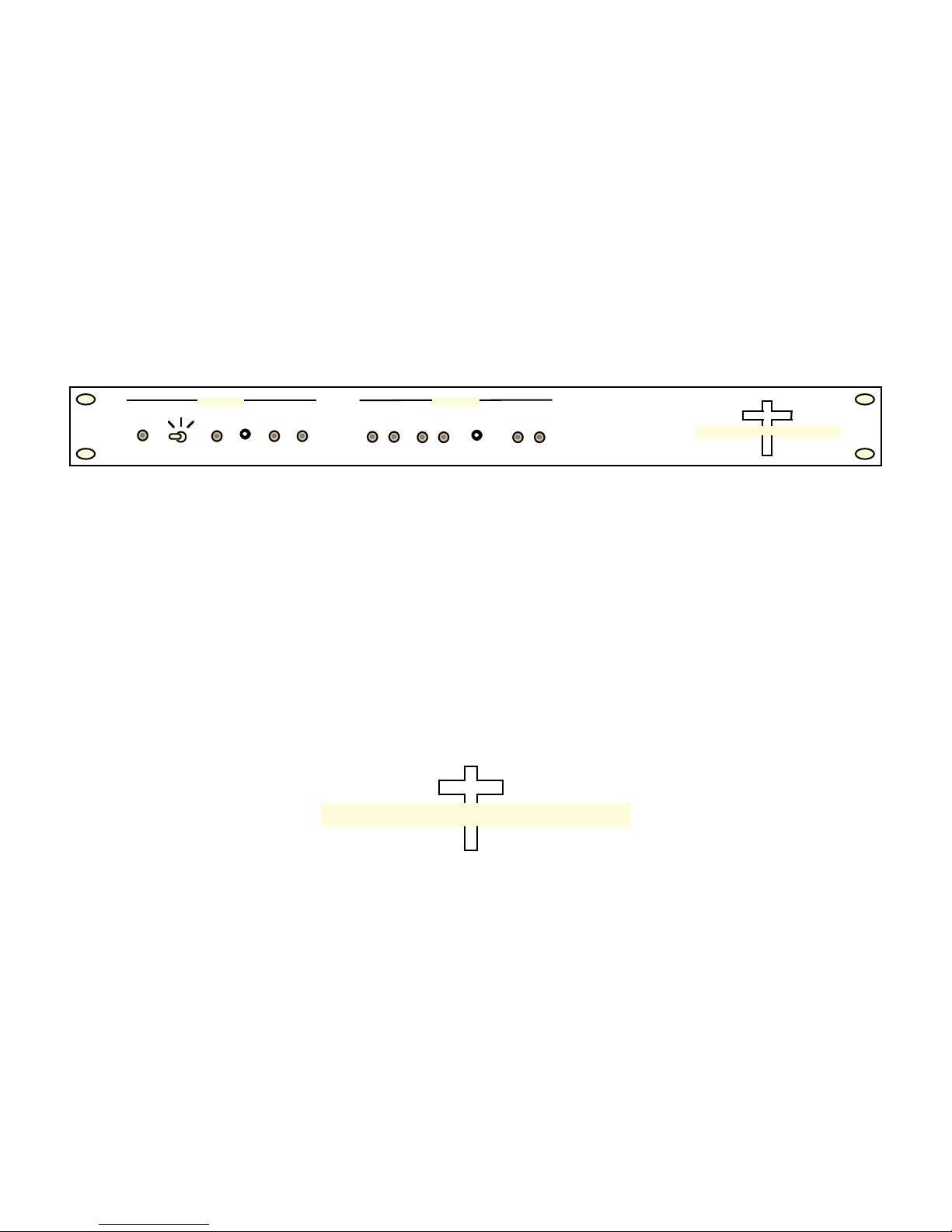
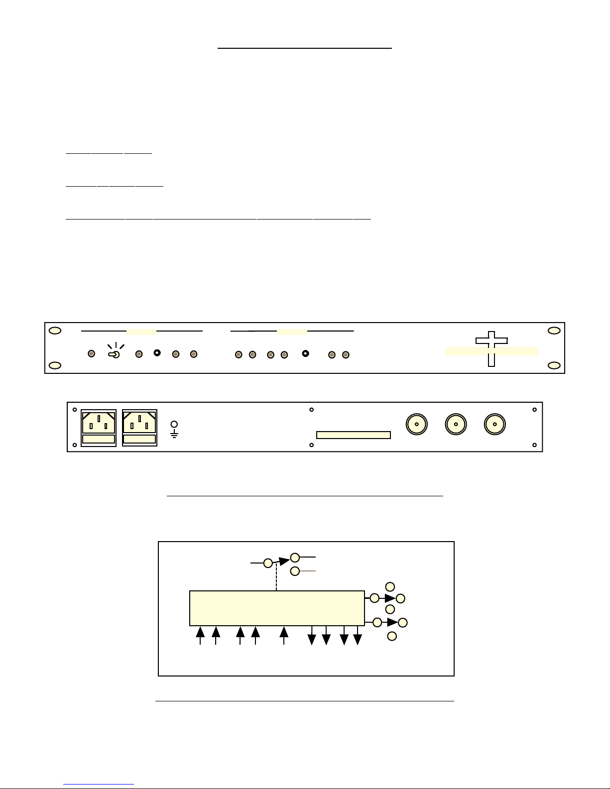
FRONT PANEL
GND
114
J7
REAR PANEL
FIGURE 1.1 Model 1582-650 Front and Rear Panels
SWITCH A
SWITCHED RF
CONTROL
LOGIC
SWITCH A1 (RF)
SWITCH A2 (RF)
CH 1
CH 2
A1
J1
AUTO
CROSS TECHNOLOGIES INC.
A
J2
A2
J3
1 2
REMOTE
FIGURE 1.2 Model 1582-650 RF Switch Block Diagrams
1582-650 Manual, Rev. C Page 3 01/26/10
1 2
ALARM
REMOTE
SW. RST
1 2
MONMA
SWITCH
R
E
N
M
RESET

1.2 Technical Characteristics
TABLE 1.1 1582-650 RF Switch Specifications*
Switch Characteristics
Impedance 50
Return Loss > 18 dB, DC to 4 GHz
> 15 dB, to 6.5 GHz
Type Relay
Isolation > 70 dB, DC to 4 GHz
> 60 dB, to 6.5 GHz
Switch Time 10 milliseconds
Insertion Loss 1 dB, DC to 4 GHz
1.5 dB, to 6.5 GHz
Configuration SPDT, no termination
Controls
Manual Select Manually select CH1 or CH2
Switch Reset Resets to CH1 in latch mode, and resets REMOTE
History Reset Resets ALARM HISTORY (prior occurrence of alarms now cleared) - LEDs only
Indicator LEDs
CH1 On-Line Turns green when Channel 1 is selected
CH2 On-Line Turns green when Channel 2 is selected
Manual Turns red when the Manual Select switch manually selects channel 1 or 2.
Alarm CH1 Turns red when Channel 1 alarm input is a closure or open (selectable)
Alarm M CH2 Turns red when Channel 2 alarm input is a closure or open (selectable)
Alarm HISTORY 1 Turns red on Channel 1 alarm and stays red until HISTORY RESET is pushed
Alarm HISTORY 2 Turns red on Channel 2 alarm and stays red until HISTORY RESET is pushed
Power CH1 Turns green when power is applied to AC1 input on the rear panel
Power CH2 Turns green when power is applied to AC2 input on the rear panel
Remote Turns amber when REMOTE control is active
Manual Select Manually select CH1 or CH2
Other
Alarm/Control Conn. Terminal Strip
RF Connectors Type N (female), 50 , (Option-S, SMA Connectors)
Mechanical 19-inch standard 1RU chassis, 1.75”High x 12”Deep
Power Redundant power supplies; 100-240 ±10% VAC, 47-63 Hz, 30 W
*+10˚C to +40˚C; 2000m max elevation; 80% max humidity; Specifications subject to change without notice.
1582-650 Manual, Rev. C Page 4 01/26/10
 Loading...