

Cross Technologies 1582-421L Instruction Manual
Instruction Manual
Model 1582-421L
Quad 1:1 Switch
June 2018, Rev. A
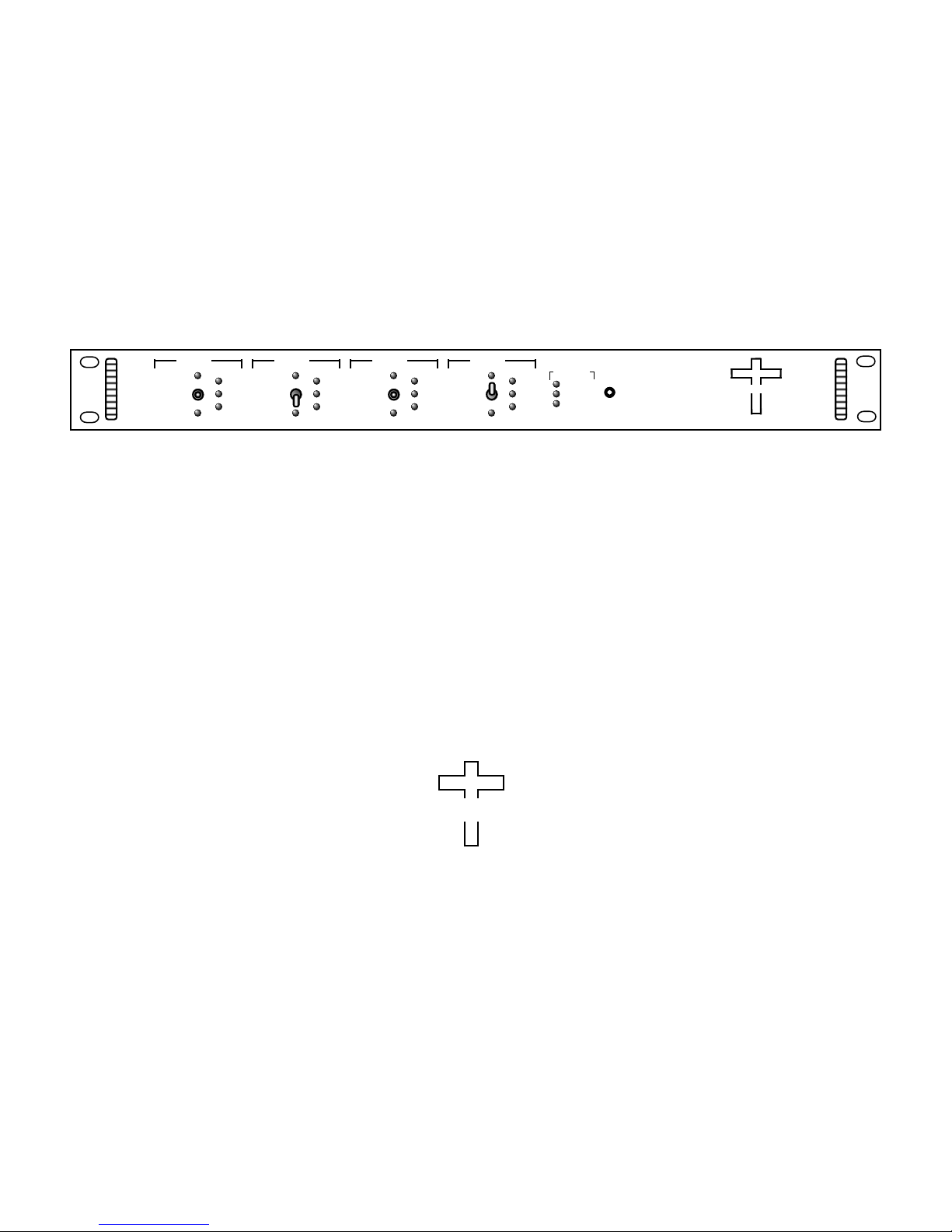
SW 1
PRIMARY -
AUTO -
BACKUP -
MAN.
REM.
AUTO
SELECT
Data, drawings, and other material contained herein are proprietary to Cross Technologies, Inc., but may be
reproduced or duplicated without the prior permission of Cross Technologies, Inc. for purposes of operating
the equipment.
When ordering parts from Cross Technologies, Inc., be sure to include the equipment
model number, equipment serial number, and a description of the part.
SW 2 SW 3 SW 4
PRIMARY
-
AUTO -
BACKUP -
SELECT
MAN.
REM.
AUTO
PRIMARY -
AUTO -
BACKUP -
MAN.
REM.
AUTO
SELECT
PRIMARY -
AUTO -
BACKUP -
SELECT
MAN.
REM.
AUTO
SWITCH
ALARM
PS1
PS2
MODEL 1582
SWITCH
SWITCH
RESET
CROSS TECHNOLOGIES INC.
CROSS TECHNOLOGIES, INC.
6170 Shiloh Road
Alpharetta, Georgia 30005
(770) 886-8005
FAX (770) 886-7964
Toll Free 888-900-5588
WEB: www.crosstechnologies.com
E-MAIL: info@crosstechnologies.com

INSTRUCTION MANUAL
MODEL 1582-421L, 1:1 Switch, M&C Monitor & Channel Select
TABLE OF CONTENTS PAGE
Warranty 2
1.0 General 3
1.1 Equipment Description 3
1.2 Technical Characteristics 4
1.3 Monitor and Control Interface 6
1.4 M&C Commands 8
2.0 Installation 10
2.1 Mechanical 11
2.2 Input and Output Signals 11
2.3 Controls and Indicators 12
2.4 Operation 13
3.0 Environmental Use Information 15
4.0 Appendix (Switch Configuration Diagrams) 19
WARRANTY - The following warranty applies to all Cross Technologies, Inc. products.
All Cross Technologies, Inc. products are warranted against defective materials and
workmanship for a period of one year after shipment to customer. Cross Technologies,
Inc.’s obligation under this warranty is limited to repairing or, at Cross Technologies, Inc.’s
option, replacing parts, subassemblies, or entire assemblies. Cross Technologies, Inc. shall
not be liable for any special, indirect, or consequential damages. This warranty does not
cover parts or equipment which have been subject to misuse, negligence, or accident by the
customer during use. All shipping costs for warranty repairs will be prepaid by the
customer. There are not other warranties, express or implied, except as stated herein.
CROSS TECHNOLOGIES, INC.
6170 Shiloh Road
Alpharetta, Georgia 30005
(770) 886-8005
FAX (770) 886-7964
Toll Free 888-900-5588
1582-421L Manual, Rev. A Page 2 06/18/18
WEB: www.crosstechnologies.com
E-MAIL: info@crosstechnologies.com
1582-421L Quad 1:1 Switch, DC-2.15 GHz, 2PDT, M&C Monitor & Channel Select
1.0 General
The 1582-421L Quad 1:1 Switch provides four 2PDT switch pairs ( SWITCH 1, 2, 3, and 4). Each switch pair independently provides Auto,
Manual or Remote (M&C) latched relay switching between PRIMARY and BACK-UP, DC - 2.15 GHz RF signals. The M&C provides monitoring
of all parameters, Switch Reset, and Channel Selection (when in Auto mode only). Alarm conditions on PRIMARY and BACK-UP are either a
contact closure to ground or an open (selectable by a rear panel DIP switch). Auto has three modes:
Auto - PRIMARY; The PRIMARY - switches from PRIMARY to BACK-UP only if PRIMARY alarms and BACK-UP is good. The unit
switches back to PRIMARY when PRIMARY is no longer in alarm or both PRIMARY and BACK-UP in alarm.
Auto - LATCH BACK-UP; Latch to BACK-UP mode - switches from PRIMARY to BACK-UP if PRIMARY alarms and BACK-UP is good
and stays in BACK-UP regardless of PRIMARY or BACK-UP alarm conditions until reset to PRIMARY by the front panel Switch Reset switch or
M&C command.
Auto - MIN SW; Minimum Auto switching mode - switching occurs if the active channel (set by the front panel Manual Select switch or M&C
command) alarms and the other channel is clear. It switches back if this channel then alarms and the other is clear.
When power is lost, the current latched state remains selected. Front panel LEDs indicate PRIMARY and BACK-UP alarms and switch position,
Auto, Remote or Manual mode, and indicates redundant power supplies are on and if the 1582-421L has an alarm condition. Rear panel DIP switches
set alarm polarity (NO or NC for alarm inputs), M&C interface, and Auto modes (PRIMARY PRIME, LATCHBACK-UP, or MIN SW). The front
panel switches manually select the signal path or selects AUTO switching (center off). The RS232 or RS422/485 M&C (Ethernet optional) monitors
switch positions, unit and switch alarm status, and selects the RF switch position (when NOT in manual mode only). A contact closure to ground
indicates an internal fault condition or loss of power. Connectors are BNC for RF signals and DB9 for M&C and alarm input and output contact
closures. It is powered by separately fused, 100-240 ±10% VAC redundant power supplies.
Applications: The 1582-421L, 1:1 Redundant Switch is software defined switch. As such it may be configured in many different ways to
support various unique Customer applications. Appendix A - CONFIGURATIONS, provides a number of Configuration Diagrams and
Interconnection Tables for each known application.
FRONT PANEL
AC1
AC2
J27 J28 J29 J30 J31 J132
B
GND
A
SW1J9B1
J7P1J8
SW2
J10P2J11
CONFIGURATION
1 ON 8
B2
J12
SWITCH
OFF
S1
J14
(Ethernet Optional)
4
9
SWITCH M&C
J15
PRIMARY M&C
4
9
J16A
15
23
6
78
4
9
BACKUP M&C
J16B
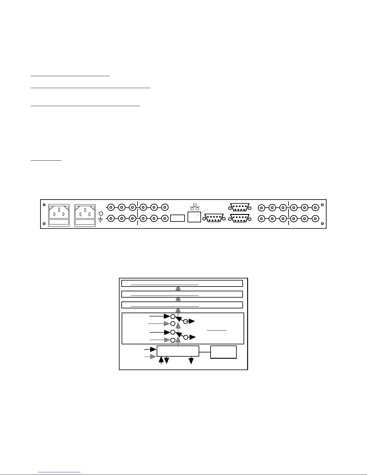
REAR PANEL
FIGURE 1.1 Model 1582-421L Front and Rear Panels
SWITCH 4 - SAME AS SWITCH 1
SWITCH 3 - SAME AS SWITCH 1
SWITCH 2 - SAME AS SWITCH 1
P1-B RF
B1-B RF
P1-A RF
B1-A RF
ALARM
PRIMARY
ALARM
BACK-UP
CONTROLLER
SUMMARY ALARM CONTACT CLOSURE
M&C
1582-421L BLOCK DIAGRAM
SW1-B SWITCHED RF
SWITCH 1
SW1-A SWITCHED RF
REAR
PANEL DIP
SWITCHES
J21 J22 J23 J24 J25 J26
15
23
6
78
15
23
6
78
SW3J3B3J4P4J5SW4
J1P3J2
B
B4
A
J6
FIGURE 1.2 Model 1582-421L Switch Block Diagram
1582-421L Manual, Rev. A Page 3 06/18/18

1.2 Technical Characteristics
TABLE 1.0 1582-421L 1:1 Switch, Specifications*
IF/L-Band Switch Characteristics
75Ω / BNC Impedance / Connectors
Return Loss
Isolation
Insertion Loss
DC Switching
Type, Configuration
Alarm and Control, M&C
Alarm Output Signal
M&C Interface / Baud Rate
Connectors, Indicators
Switch: Power, Auto, Remote,
Manual, Alarm
12 dB minimum, ≥ 14 dB typical; DC to 1.5 GHz
10 dB minimum, ≥ 12 dB typical; 1.5 to 2.5 GHz
≤ ±0.5 dB, 40 MHz BW, ≤ ±1 dB, 1 GHz BW Frequency Response
55 dB minimum, ≥ 60 dB typical, DC to 1.5 GHz
45 dB minimum, ≥ 50 dB typical; 1.5 to 2.5 GHz
1.5 dB maximum, ≤ 1.0 dB typical; DC to 1.5 GHz
2.5 dB maximum, ≤ 2.0 dB typical; 1.5 to 2.5 GHz
≤ 10 milliseconds Switch Time
48VDC, maximum; 2 Amps, maximum; 60VA maximum
Latching Relay, 2PDT, No Termination
Form C relay: 30VDC, 0.5A maximum
RS232C or RS422/485, Selectable/9600 (Ethernet Optional)
Front Panel Switch Auto/Manual
Front Panel Switches or M&C Switch Reset
Green, Green, Yellow, Red, Red LED - Form C contact closure, M&C
Unit: Alarm, Good, Online
Red, Green, Blue
Connectors, Other
RF, Connectors
Ext. Alarms In, M&C Connector
75Ω BNC (female)
DB9 (female)
1 RU, 19 inch Standard Chassis, 1.75” high x 16.0” deep Size
Power
*10˚C to 40˚C; Specifications subject to change without notice. Cross Technologies, Inc.
Redundant 100-240 ±10% VAC, 47-63 Hz.,
20 Watts maximum Power Supplies
(Technical Characteristics continued on page 5...)
1582-421L Manual, Rev. A Page 4 06/18/18

(Technical Characteristics continued from page 4...)
There are four(4) Ethernet Options Available
Ethernet M&C Remote Interface. Provides Web Browser user interface. W- 8
W-18
W-28
W-828
Ethernet M&C Remote Interface. Provides BOTH Web Browser & SNMP Ethernet user interfaces.
Includes SNMP MIB File.
Ethernet M&C Remote Interface. Provides Direct TCP/IP and Telnet® addressability Ethernet interface.
Ethernet M&C Remote Interface. Provides All three (3) - Web Browser, SNMP Ethernet and
Direct TCP/IP and/or Telnet® addressability Ethernet interfaces.
Connectors/Impedance
D4
SS4
* 10˚C to 40˚C; Specifications subject to change without notice © Cross Technologies, Inc.
50Ω BNC
50Ω SMA
1582-421L Manual, Rev. A Page 5 06/18/18
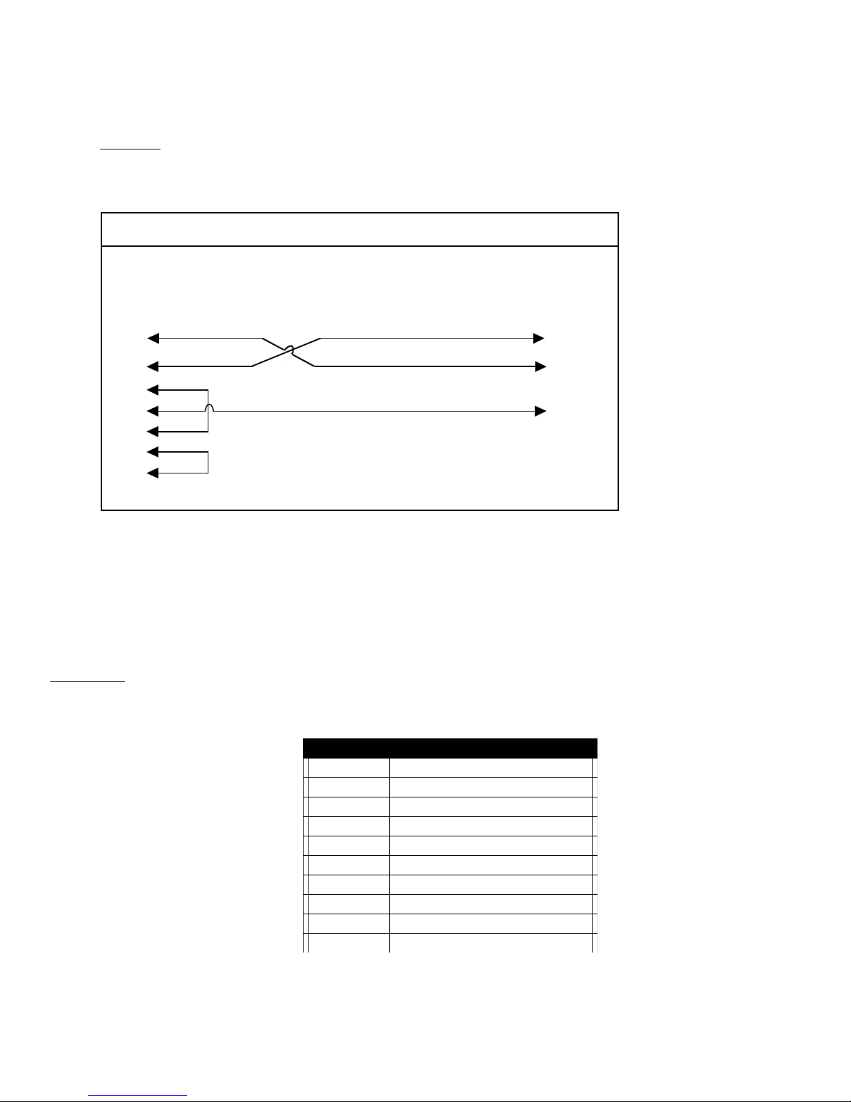
1.3 Monitor and Control Interface
J15 Pinouts (RS-232C/422/485)
Pin Function
A) Remote Serial Interface
Protocol: RS232C, 9600 baud rate, no parity, 8 data bits, 1 start bit, and 1 stop bit.
(RS232C, RS-422, or RS-485)
M&C Cable Diagram - Cross Technologies Frequency Converters
Female DB-9
PC Com Port
1
2
3
4
5
6
7
8
9
Connector: Rear panel, DB-9 Female:
J15 PINOUT (RS-232C/422/485):
1
2
3
4
5
6
7
8
9
1582-421L Manual, Rev. A Page 6 06/18/18
1 Rx2 Rx+ (RS-232C)
3 Tx+ (RS-232C)
4Tx5GND
6 Alarm Relay: Common
7 Alarm Relay: Normally Open
8 Not Used
9 Alarm Relay: Normally Closed

Connector: J16 PINOUT (W102):
J16 Pinouts (W102)
J16 Pinouts (W102)
Pin Function
J16 Pinouts (W103)
J16 Pinouts (W103)
Pin Function
(J16A = PRIMARY, 16B = BACKUP)
Connector: J16 PINOUT (W103):
(J16A = PRIMARY, 16B = BACKUP)
1 Unit #1 Alarm Input
2 Unit #2 Alarm Input
3 Unit #3 Alarm Input
4 Unit #4 Alarm Input
5 Unit #1 Alarm Ground
6 Unit #2 Alarm Ground
7 Unit #3 Alarm Ground
8 Unit #4 Alarm Ground
9 Ground
1 DO NOT USE
2 UNIT #1 RS232 TX
3 UNIT #1 RS232 RX
4 DO NOT USE
5 GROUND
6 GROUND
7 GROUND
8 DO NOT USE
9 Alarm Input
1582-421L Manual, Rev. A Page 7 06/18/18

1.4 M&C Commands
The following tables summarize the M&C Commands applicable to the 1582-421L Switch.
* PLEASE NOTE: The two character {aa} prefix, shown in the table below, is present ONLY when RS485 is selected.
Commands specific to a switch must be preceeded by *i where i is the switch number.
Table 2.0 Model 1582-421L - M&C Commands
Table 2.0: Model 1582-421L 1:1 Switch, M&C Commands
Command Description Syntax Command Function
{aa*iCPx} Set RF Switch Position
where i = 1, 2, 3, or 4 designating the switch number:
aa = unit address, range = 00 to 31, only used if interface is RS485, otherwise omit.
P = Command Code
x = desired switch position, P or BU. Once the switch position is selected remotely, the
switch is in "Remote Mode” and the front panel remote indicator will light. The unit will
remain in Remote Mode until one of the following occurs:
1. A Switch Reset command ( {aa*iCR} ) is issued.
2. The front panel Switch Reset button is pressed.
{aa*iCR} Switch Reset
3. The switch position is manually selected via the front panel
Manual Select toggle switch.
If the switch is already in manual mode (i.e, the front panel toggle switch is in the
PRIMARY or BACKUP position) then the switch will ignore this command.
example: {*3CPB}
Will (remotely) set Switch 3 to BACK-UP. The unit will ignore this command if the switch
is in manual mode. The unit will reply with the '>' character if the command is sucessfully
processed.
where: i = 1, 2, 3, or 4 designating the switch number.
aa = unit address, range = 00 to 31, only used if interface is RS485, otherwise omit.
(M&C Commands continued on page 9)...
1582-421L Manual, Rev. A Page 8 06/18/18
R = command code
This command has the same effect as pressing the front panel Switch Reset button.
example: {aa*iCR2}
Will return Switch 2 to Auto mode if it is in Remote mode. Also, this command will reset
the switch position if it is currently "latched" to the BACK-UP position (and if PRIMARY
is not alarmed).
The unit will reply with the '>' character if the command is sucessfully processed.

(M&C Commands continued from page 8)...
Table 2.0: Model 1582-421L 1:1 Switch, M&C Commands continued...
Command Description Syntax Command Function
{aa*iCH}Clear Alarm History
where i = 1, 2, 3, or 4 designating the switch number
aa = unit address, range = 00 to 31, only used if interface is RS485, otherwise omit.
R = command code
This command will clear the state of the designated switch's alarm history.
example: {aa*iCH}
The unit will reply with the '>' character if the command is sucessfully processed.
where: {aaCXxx} Set RS485 Address
aa = unit address, range = 00 to 31, only used if interface is RS485, otherwise omit.
X = command code
XX = unit address, range = 00 to 31
example: {CX12} will set the unit's RS485 address to 12.
The unit will reply with the '>' character if the command is sucessfully processed.
.
1582-421L Manual, Rev. A Page 9 06/18/18

1.5 Status Requests/Inquiries
The following tables summarize the status requests/queries applicable to the 1582-421L Switch.
* PLEASE NOTE: The two character {aa} prefix, shown in the table below, is present ONLY when RS485 is selected.
Status Requests specific to a switch must be preceeded by *i where i is the switch number.
Table 2.1 Model 1582-421L - Status Requests/Inquiries
Table 2.1: Model 1582-421L 1:1 Switch Status Requests/Inquiries
Command Description Syntax Command Function
{*iaaSS} Get Switch State
{*iaaSA} Get Switch Alarm Status
returns: {*iaaSSbc}
where i = 1, 2, 3, or 4 designating the switch number.
aa = unit address, range = 00 to 31, only used if interface is RS485, otherwise omit.
S = command code
b = Switch Position: P (primary) or B (backup)
c = Switch Mode: ‘M’ if in Manual Mode, ‘R’ if in Remote Mode, and ‘A’ if in Auto Mode.
The unit will append the ʻ>ʼ character if the command is successfully processed.
returns: {*iaaSAbcde}
where i = 1, 2, 3, or 4 designating the switch number.
aa = unit address, range = 00 to 31, only used if interface is RS485, otherwise omit.
A = command code
b = PRIMARY alarm status: 0 if alarm is off, 1 if alarm is on.
c = PRIMARY alarm history status: 0 if no alarm history, 1 if an alarm occured
d = BACK-UP alarm status: 0 if alarm is off, 1 if alarm is on
e = BACK-UP alarm history status: 0 if no alarm history, 1 if an alarm occured
The unit will append the ʻ>ʼ character if the command is successfully processed.
Get Auto Switching
Mode Status
{aaSM}
(M&C Status Requests/Inquiries continued on page 11)...
1582-421L Manual, Rev. A Page 10 06/18/18
returns: {aaSAx}
where:
aa = unit address, range = 00 to 31, only used if interface is RS485, otherwise omit
M = command code
X = 1 for CH1 Prime Mode, X = 2 for Latch to CH2 Mode, X = 3 for Minimum
Auto Switching Mode.
The unit will append the ʻ>ʼ character if the command is successfully processed.
 Loading...