

Cross Technologies 1200-88 Instruction Manual
Instruction Manual
Model 1200-88
IF Amplifier
August 2010 Rev. A
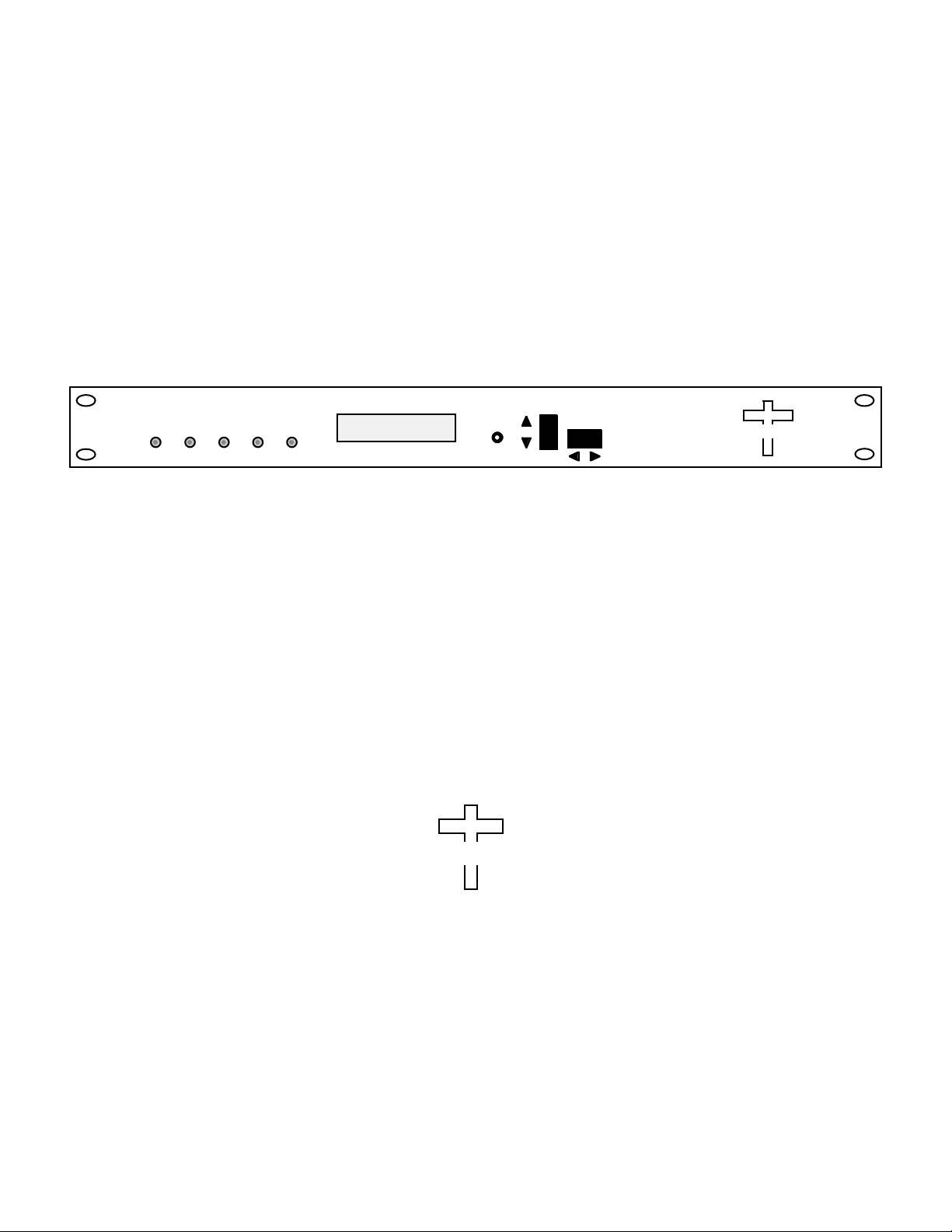
MODEL 1200
G1=-10 LVL1=<+5
G2=+15 LVL2= +12
REMOTECH2
CH1
PEAK
Data, drawings, and other material contained herein are proprietary to Cross Technologies, Inc.,
but may be reproduced or duplicated without the prior permission of Cross Technologies, Inc.
for purposes of operating the equipment. Printed in USA.
When ordering parts from Cross Technologies, Inc., be sure to include the equipment
model number, equipment serial number, and a description of the part.
POWER ALARM
PEAK
MENU
EXECUTE
AMPLIFIER
CROSS TECHNOLOGIES INC.
CROSS TECHNOLOGIES, INC.
6170 Shiloh Road
Alpharetta, Georgia 30005
(770) 886-8005
FAX (770) 886-7964
Toll Free 888-900-5588
WEB: www.crosstechnologies.com
E-MAIL: info@crosstechnologies.com

INSTRUCTION MANUAL
MODEL 1200-88 Dual IF Amplifier
TABLE OF CONTENTS PAGE
Warranty 2
1.0 General 3
1.1 Equipment Description 3
1.2 Technical Characteristics 4
1.3 Monitor & Control Interface 5
2.0 Installation 7
2.1 Mechanical 7
2.2 Rear Panel Inputs & Outputs 8
2.3 Front Panel Controls & Indicators 9
2.4 Operation 10
2.5 Menu Settings 11
3.0 Environmental Use Information 14
WARRANTY - The following warranty applies to all Cross Technologies, Inc. products.
All Cross Technologies, Inc. products are warranted against defective materials and
workmanship for a period of one year after shipment to customer. Cross Technologies,
Inc.’s obligation under this warranty is limited to repairing or, at Cross Technologies,
Inc.’s option, replacing parts, subassemblies, or entire assemblies. Cross Technologies,
Inc. shall not be liable for any special, indirect, or consequential damages. This warranty
does not cover parts or equipment which have been subject to misuse, negligence, or
accident by the customer during use. All shipping costs for warranty repairs will be
prepaid by the customer. There are not other warranties, express or implied, except as
stated herein.
CROSS TECHNOLOGIES, INC.
6170 Shiloh Road
Alpharetta, Georgia 30005
(770) 886-8005
FAX (770) 886-7964
Toll Free 888-900-5588
WEB: www.crosstechnologies.com
E-MAIL: info@crosstechnologies.com
1200-88 Manual, Rev. A Page 2 8/18/10
MODEL 1200-88 Dual IF Amplifier
1.0 General
1.1 Equipment Description
The 1200-88 IF Amplifier is a dua l channel amplifier each providing manual gain control (MGC) for a 0.1 to
100 MHz IF signal for a -50 to 0 dBm input signal. The gain can be manually adjusted from -25 to +25 dB for
up to a +10 dBm output. The 1200-88 has a band limiting lowpass filter. Multi-function push button switches
select the gain of each channel (-25 to +25 dB, selectable in 1 dB steps) and the settings appear on the LCD
display. Front panel LEDs light when DC power is applied (green) or the output level exceeds +13 dBm (red).
Connectors are BNC female for IF input and output. A DB9 c onnector provides indication and remote control
of gain via a 9600 baud, RS232C interface. The 1200-88 is powered by a 100-240 ±10% VAC switching power
supply and is housed in a 1RU x 16” deep chassis.
MODEL 1200
AMPLIFIER
INPUT
J4 J5J1
CROSS TECHNOLOGIES INC.
OUTPUT
CH1
PEAK
AC
POWER ALARM
PEAK
GND
G1=-10 LVL1=<+5
G2=+15 LVL2= +12
REMOTECH2
MENU
EXECUTE
FRONT PANEL
INPUT
J2
CHANNEL 1 CHANNEL 2
OUTPUT
MONITOR
AND
CONTROL
J10
15 234
6789
REAR PANEL
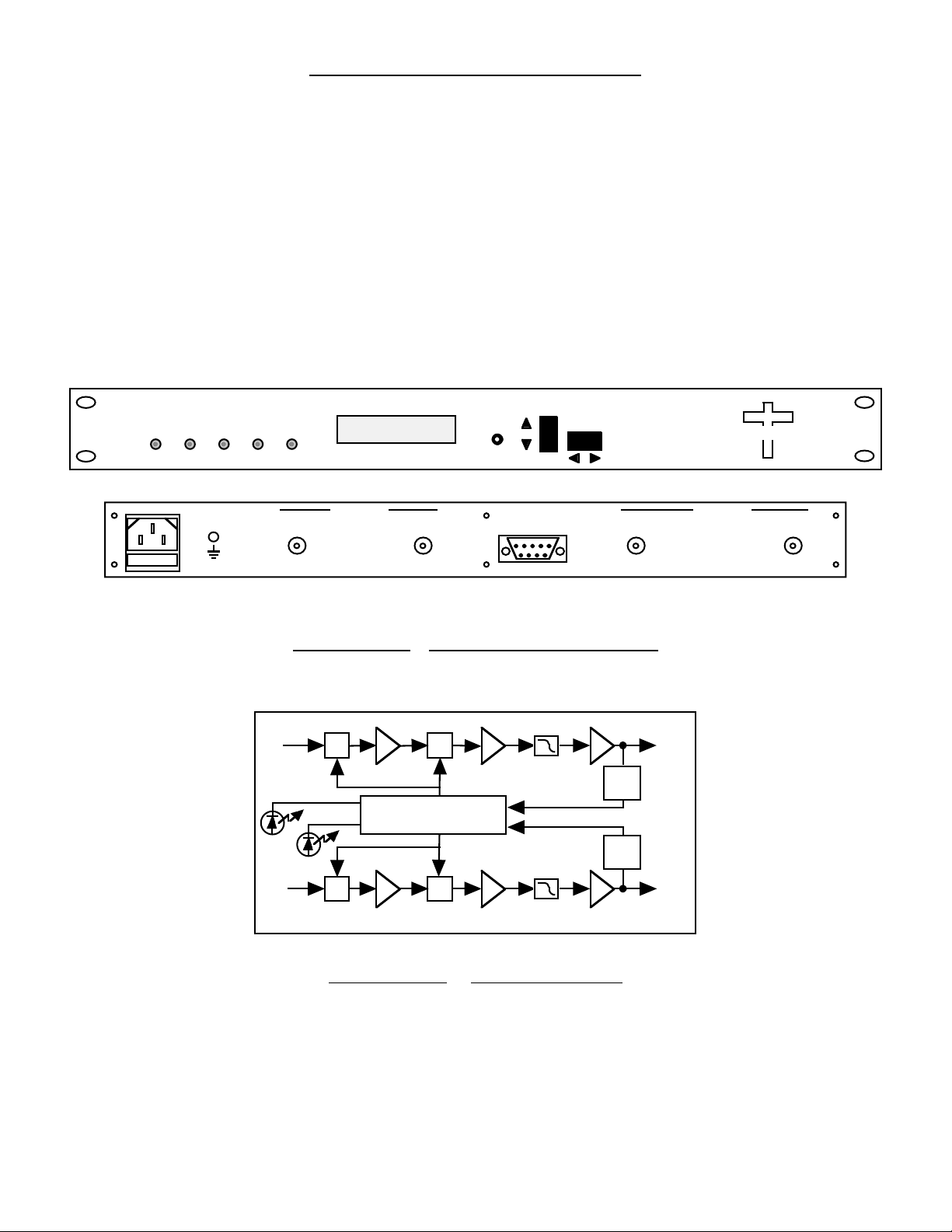
FIGURE 1.1 Front and Rear Panels
IF 1
IN
PK LED 1
IF 2
IN
ATT ATT
PK LED 2
ATT ATT
CONTROLLER
FIGURE 1.2 Block Diagram
PK
Alarm1
PK
Alarm2
IF 1
OUT
IF 2
OUT
1200-88 Manual, Rev. A Page 3 8/18/10

1.2 Technical Characteristics
TABLE 1.0 1200-88 Dual IF Amp Specifications (each amp)*
Input Characteristics
Impedance 50
Return Loss 18 dB
Frequency 0.1 to 100 MHz
Input Level -50 to 0 dBm
Input 1 dB compression +5 dBm @ min. gain
Output Characteristics
Impedance 50
Return Loss 18 dB
Output level +10 dBm, max.
Output 1 dB compression +15 dBm
Channel Characteristics
Gain range (adjustable) -25 to +25 dB (Front Panel Adjustable)
Frequency Response ±1.0 dB, 0.1-100 MHz; ±0.5 dB, any 20 MHz segment
Group Delay, max. ±2 ns, max. 0.1 to 100 MH
Controls, Indicators
Level Adjust pushbutton switches or REMOTE; setting shown on LCD display;
Set to -25 to +25 dB (+10 dBm max. out)
Level Peak Red LED lights when output level exceeds +13 dBm
Power Green LED
Remote Yellow LED
Alarm Red LED
Other
IF Connector BNC (female)
Alarm/Remote Connector DB9 - NO or NC contact closure on Alarm; M&C 9600 Baud, RS232C
Size 19 inch, 1RU standard chassis 1.75” high X 16.0” deep
Power 100-240 ±10% VAC, 47-63 Hz, 45 watts max.
Options
Q RS-422/RS-485 Remote capability
Connector options see TABLE 2.2
*+10˚C to +40˚C; Specifications subject to change without notice
1200-88 Manual, Rev. A Page 4 8/18/10
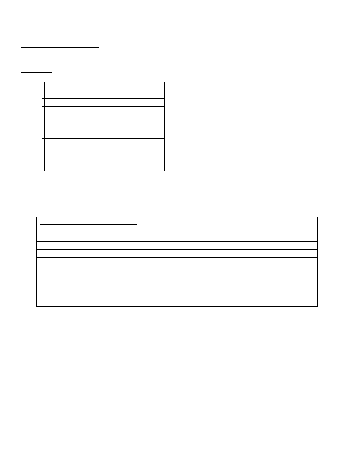
1.3 Monitor and Control Interface
J10 Pinouts
Pin Function
Table 1.1 1200-88 Status Reequests
Command Syntax* Description
* PLEASE NOTE: The Address (aa) should only be used when RS-485 is selected.
A) Remote serial interface
Protocol: RS-232C, 9600 baud rate, no parity, 8 data bits, 1 start bit, and 1 stop bit.
Connector: Rear panel, DB-9 male.
1Rx2 Rx+ (RS-232C)
3 Tx+ (RS-232C)
4Tx5GND
6 Alarm Relay: Common
7 Alarm Relay: Normally Open
8Not Used
9 Alarm Relay: Normally Closed
B) Status Requests - Table 1.1 lists the status requests for the 1200-88 and briefly describes them.
Command Status {aaS0} Returns {aaS0bbbcccddddeeeefg} where:
• bbb = GAIN 1 (range -25 to +25 dB)
• ccc = GAIN 2 (range -25 to +25 dB)
• dddd = LEVEL 1 (range <+5, +5, +6,..., +14, +15, >+15)
• eeee = LEVEL 2 (range <+5, +5, +6,..., +14, +15, >+15)
• f = 0 if NO CH1 peak alarm
= 1 if CH1 peak alarm
• g = 0 if NO CH2 peak alarm
= 1 if CH2 peak alarm
1200-88 Manual, Rev. A Page 5 8/18/10
 Loading...