

Cross Technologies 1200-03 Instruction Manual
Instruction Manual
Model 1200-03
IF Processor
January 2009 Rev B
GAIN
MODEL 1200
IF PROCESSOR
T3R1 R2 R3 T1 T2
DCOVERRIDELOCALDIG2FDMDIG1
CROSS TECHNOLOGIES, INC.
RX
IF MON
DIG1
SW1
FDM
SW2
ONONON
DIG2
SW3 SW4 J2J1
LOCAL
REMOTE
TX
IF MON
FRONT
Data, drawings, and other material contained herein are proprietary to Cross Technologies, Inc.,
but may be reproduced or duplicated without the prior permission of Cross Technologies, Inc.
for purposes of operating the equipment.
When ordering parts from Cross Technologies, Inc., be sure to include the equipment
model number, equipment serial number, and a description of the part.
CROSS TECHNOLOGIES, INC.
6170 Shiloh Road
Alpharetta, Georgia 30005
(770) 886-8005
FAX (770) 886-7964
Toll Free 888-900-5588
WEB www.crosstechnologies.com
E-MAIL info@crosstechnologies.com

INSTRUCTION MANUAL
MODEL 1200-03 IF PROCESSOR
TABLE OF CONTENTS PAGE
Warranty 2
1.0 General 3
1.1 Equipment Description 3
1.2 Technical Characteristics 4
1.3 Use Information 6
2.0 Installation 7
2.1 Mechanical 7
2.2 Rear I/O’s, Control 8
2.3 Front Panel I/O’s, Indicators 8
2.4 Operation 9
WARRANTY - The following warranty applies to all Cross Technologies, Inc. products.
All Cross Technologies, Inc. products are warranted against defective materials and
workmanship for a period of one year after shipment to customer. Cross Technologies,
Inc.’s obligation under this warranty is limited to repairing or, at Cross Technologies,
Inc.’s option, replacing parts, subassemblies, or entire assemblies. Cross Technologies,
Inc. shall not be liable for any special, indirect, or consequential damages. This
warranty does not cover parts or equipment which have been subject to misuse,
negligence, or accident by the customer during use. All shipping costs for warranty
repairs will be prepaid by the customer. There are not other warranties, express or
implied, except as stated herein.
CROSS TECHNOLOGIES, INC.
6170 Shiloh Road
Alpharetta, Georgia 30005
(770) 886-8005
FAX (770) 886-7964
Toll Free 888-900-5588
1200-03 Manual, Rev. B Page 2 01/08/09
WEB www.crosstechnologies.com
E-MAIL info@crosstechnologies.com
MODEL 1200-03 IF PROCESSOR
1.0 General
1.1 Equipment Description - The 1200-03 IF Processor consists of a transmit and receive side. The receive
side consists of one receive IF signal going through an Automatic Gain Control (AGC) amplifier and then
split into three signals, DIG1RX, FDMRX, DIG2RX each having variable attenuators to adjust their levels
over a 30dB output range via front panel multi-turn potentiometers. The AGC amplifier provides Automatic
Gain Control for a 50 to 90 MHz IF signal for a -80 to 0 dBm input level to a -35dBm ±10dB output. A front
panel monitor port provides a monitor signal out of the AGC amplifier.
The transmit side consists of three transmit IF signals combined into one. Transmit DIGTX, FDMTX, and
DIG2TX signals each pass through individual attenuators controlled via front panel multi-turn
potentiometers and a switch that is controlled remotely through a DB9 connector or locally with three 2PDT
switches located on the front panel.
A 2PDT switch on the front panel selects either REMOTE or LOCAL operation. On the DB9 connector a
closure to +V will turn the corresponding transmit channels on. A local override feature is included such that
when the REMOTE/LOCAL 2PDT switch on the front panel is left in the LOCAL position, the override pin
on the DB9 can be set to +V to override the LOCAL control and allow for REMOTE control. DIG1 and
DIG2 on both transmit and receive sides are 75 in/out while FDM on both transmit and receive sides are
50 in/out. When power is removed from the 1200-03, the FDM TX and FDM RX signals pass through to
the output.
The IF in and out connectors are BNC female. All circuitry is on a single PCB housed in a 1RU X 14”
deep chassis. An internal switching power supply powers the unit with a 100-240 ±10% VAC, 47-63 Hz
input.
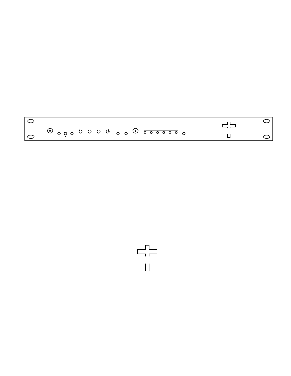
GAIN
CONTROL
J105
MODEL 1200
IF PROCESSOR
T3R1 R2 R3 T1 T2
DC
DIG1
RX OUT
J106
C
ROSS
FDM
RX OUT
J107
T
ECHNOLOGIES, INC.
DIG2
RX OUTRXIF IN
J108 J109
RX
IF MON
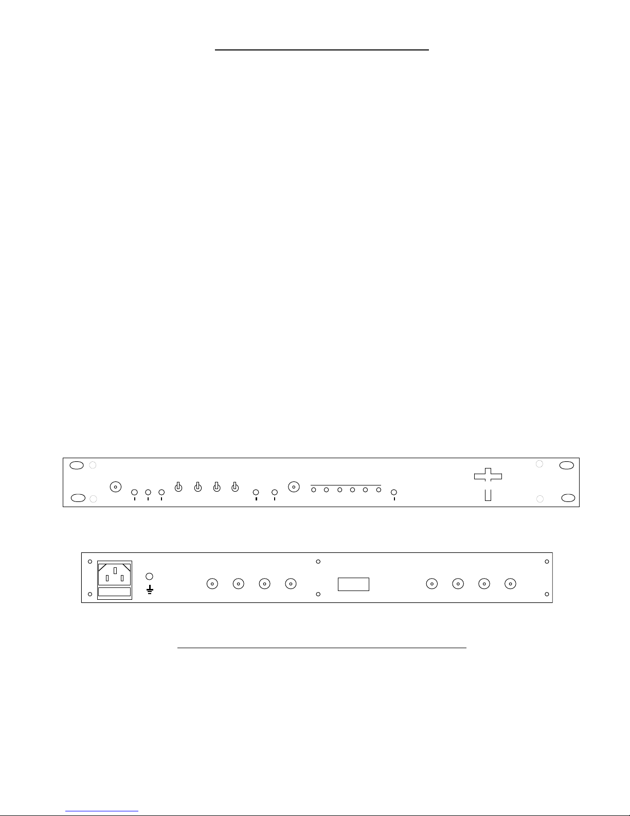
GND
DIG1 FDM DIG2
SW1 SW2 SW3 SW4
J1 J2
AC IN
DIG1
TX IN
J101
LOCAL
ONONON
REMOTE
FDM
TX IN
J102
OVERRIDELOCALDIG2FDMDIG1
DIG2
TX INTXIF OUT
J103 J104
TX
IF MON
FRONT
REAR
FIGURE 1.1 Model 1200-03 Front and Rear Panels
1200-03 Manual, Rev. B Page 3 01/08/09

1.2 Technical Characteristics
TABLE 1.1 1200-03 IF Processor Specifications*
RX Input Characteristics
Impedance/Return Loss 50 /18 dB
Frequency 50 to 90 MHz
Input Level Range/1dB 0 to -80 dBm / +5 dBm
RX Output Characteristics
Impedance/Return Loss FDM RX 50 / 18dB; DIG1, DIG2 RX 75 /18 dB (with 5dB
attenuation on each channel)
Output Level, nom/max -35 ± 10 dBm / -10 dBm
Output Level Adjust -35 to -65 dB ± 10 dB at -35 dBm nominal
RX IF Mon Output Level -35 ± 10 dBm
RX Channel Characteristics
Gain, AGC -35 to +45 dB range
Frequency Response ±1.0 dB
TX Input Characteristics
Impedance/Return Loss FDM TX 50 / 18dB; DIG1, DIG2 TX 75 /18 dB (with 5dB
attenuation on each channel)
Frequency 50 to 90 MHz
Input Level Range -20 to +5 dBm
Input Level Adjust 0 to -30 dBm with 0 dBm in
TX Output Characteristics
Impedance/Return Loss 50 /18 dB
Output Level Range/1dB -50 to +5 dBm / +10 dBm
TX Channel Characteristics
Gain Adjustment 0 to -30 dB, each channel individually adjustable
Frequency Response ±1.0 dB
Group Delay 5 ns, max
TX Switch Characteristics
Isolation, Switch off 60 dB
Isolation, Port to Port 50 dB, all “ON” and 5dB attenuation on each channel
Switch Time 10 ms
Controls, Indicators
Front Panel Controls
SW1, SW2, SW3 DIG1 TX, FDM TX, DIG2 TX switches (2PDT)
SW4 LOCAL/REMOTE switch (2PDT)
Front Panel Indicators
DIG1, FDM, DIG2 Green LED indicates DIG1 TX, FDM TX, DIG2 TX are “ON”
OVERRIDE Yellow LED indicates override of LOCAL control
LOCAL Red LED indicates SW4 set to LOCAL control
DC Green LED indicates power is supplied to the unit
Front Panel Monitors
J1, J2 RX AGC Monitor, TX IF Out Monitor
Other
IF Connectors BNC, female
Connector, Control DB9, female
Size 19 inch standard chassis 1.75”high X 14.0” deep
Power 100-240 ±10% VAC, 47 - 63 Hz, 30 watts max.
*+10 to +40 degrees C; Specifications subject to change without notice
1200-03 Manual, Rev. B Page 4 01/08/09
 Loading...