

Page 1
OPERATOR’S MANUAL
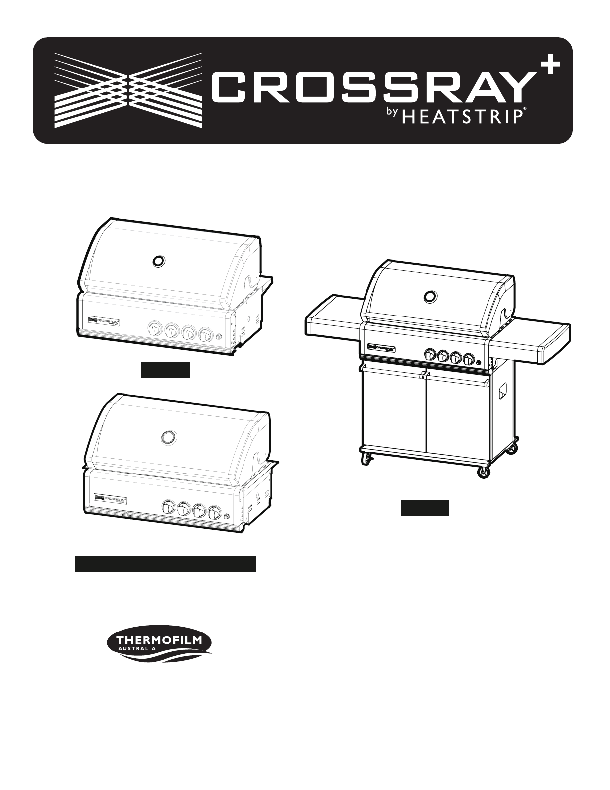
TCS4FL
Optional Side Trim Brackets for TCS4FL
Thermolm Australia Pty Ltd
17 Johnston Court, Dandenong South,
Victoria 3175, Australia
Telephone: (03) 9562 3455
Email: info@thermolm.com.au
TCS4PL
CONTACT INFORMATION
For spare parts order or service warranty and Natural
Gas Conversion queries call (03) 9562 3455 or email
info@thermolm.com.au Your purchase receipt is
required for all warranty claims.
Retain manual for future reference.
MANUAL # P80196010B - DATE:2020/10/13
1
Page 2

TABLE OF CONTENTS
HOSE AND REGULATOR SAFETY
GAS SAFETY / TECHNICAL DATA
ASSEMBLY
OPERATING PROCEDURE
FAULT FINDING
CARE & MAINTENANCE
PARTS LIST / DIAGRAM
WARRANTY
CONNECTING NATURAL GAS
GAS INSTALLATION CODES
Barbecues must be used in accordance with the installation requirements of your gas supply authority, or the appropriate installation code issued by Standards Australia
AS/NZ 5601.
Barbecues for use with bottled gas are labelled ‘propane
gas’ or ‘Universal LPG’.
Barbecues for use with natural gas are labelled ‘natural
gas’ and must be installed by an licensed plumber/gas
tter. Check the gas type sticker attached to the barbecue.
2 - 7
8 - 13
14
15
16 -18
20 - 21
22
23
The regulator and hose assembly supplied with the barbe-
cue are suitable for propane.
A gas regulator adjusted to have an outlet pressure of
2.75kPA is supplied for connection to the Propane gas
cylinder. The pressure regulator and hose assembly
supplied with the barbecue must be used. Replacement
pressure regulators and hose assemblies must be those
specied by the barbecue manufacturer.
When connecting the hose and regulator assembly to the
gas cylinder, take care to avoid unnecessary twisting of the
exible hose. Also, take care to avoid a loose connection
with the gas cylinder. After the assembly has been secured,
turn on the gas and check for leaks by brushing a soap and
water solutio n over all visibl e and accessible gas line
connections. Include checking those connections which
were made by your supplier. The presence of bubbles will
indicate a gas leak. Refer to page 5. If you are unable to
correct the leak by tightening the connections, turn off the
gas and contact the supplier immediately.
Always ensure the barbecue is kept away from ammable
materials and the gas cylinder clear of any heat source.
When changing over from an empty gas cylinder to a full
one make sure this procedure is carried out in a ame free
atmosphere.
Inspect the gas hose assembly when exchanging the gas
cylinder, or at least once a year, whichever is more frequent.
If the O-Ring or PVC hose is cracked, cut, abraded or
damaged in any way, the appliance must not be operated.
The complete assembly must be replaced if damaged and
when statutory conditions require it. Contact your place of
purchase if uncertain.
LOCATION OF YOUR BARBECUE
CLEARANCES
Minimum Clearances from combustible materials must be:
Rear - 450mm Sides - 250mm Top - 1000mm
Opening at the rear and sides of the appliance provide air
for combustion and must not be obstructed.
DIMENSIONS
Height
- Hood closed: 1258mm; Hood open: 1500mm
Width
- TCS4PL: 1700mm
Depth
- Hood closed: 542mm; Hood open: 696mm
DO NOT use your barbecue in garages, porches, sheds,
breezeways, or other enclosed areas. Your barbecue is to
be used OUTDOORS. The barbecue is not intended to be
installed in or on recreational vehicles and/or boats.
DO NOT LOCATION OF YOUR BARBECUE under any surface that will burn. Do not obstruct the ow of combustion
and ventilation air around the barbecue housing. Refer to
page 6.
2
Page 3

PROTECT CHILDRENWARNING
Read carefully before assembling and operating your •
barbecue And retain the manual for future reference.
Failure to comply with these instructions could result •
in a re or explosion which could cause serious bodily
injury, death or property damage.
Accessible parts may be very hot.•
Keep young children away.•
Any modications of this barbecue may be dangerous.•
Do not move this barbecue during use.•
Turn off gas supply at the gas cylinder after use.•
Parts sealed by the manufacturer or their agent must •
not be manipulated by the user. This barbecue is only
to be used outdoors.
This appliance shall not be used indoors.•
Do not store a spare gas cylinder under or near this •
barbecue.
Never operate this barbecue without a regulator.•
If you smell gas•
Shut off ga s to the barb ecue at its s ource, if 1.
possible.
Extinguish any open ame.2.
Open hood/oven door.3.
if odour continues immediately call your gas 4.
supplier or re department.
Do not con nect you r ba rbecue to a g as cyl inder •
exceeding 9Kg capacity.
Never connect an unregulated gas cylinder to your •
barbecue.
If storing the barbecue indoors. The gas cylinder must •
be removed.
Store gas cylinder outdoors in a well ventilated area. •
Refer to Page 6 for gas cylinder safety.
Do not spray aerosols in the vicinity of this appliance •
while it is in operation.
Do not use or store ammable materials in or near this •
appliance.
Do not place articles on or against this appliance.•
Do not modify this appliance.•
Keep children away from barbecue during use and until
barbecue has cooled after you have nished. Do not allow
children to operate barbecue or to swing on handle.
Always ensure that no sporting or physical activities are
carried out in close proximity to the barbecue during use
and while still hot.
GAS CYLINDER USE & SAFETY
This is a low pressure barbecue and must only be used with
the hose and regulator supplied. Your barbecue is designed
for use with 4.5Kg or 9Kg propane gas cylinders certied to
AS 2469.
DO NOT CONNECT YOUR BARBECUE TO A GAS
CY LINDER LESS TH AN OR EXC EEDING THIS
CAPACITY.
The gas cylinder should be lled by a reputable gas supplier
and visually inspected and re-qualied at each lling.
Always keep cylinder in an upright position. Always close
the cylinder valve when the barbecue is not in use.
Do not subject gas cylinder to excessive heat.
NEVER STORE YOUR GAS CYLINDER INDOORS.
If you store your barbecue indoors, ALWAYS
disconnect the gas cylinder first and store the
cylinder safely outside.
Cylinders must be stored outdoors in a well ventilated
area out of reach of children, and must not be stored in a
building, garage or any other enclosed area.
3
Page 4

Certication Number
IMPORTANT:
AGA Certicate: AGA 8441 G
CONNECTIONS
Inlet thread: 5/8 - 18UNF (3/8 SAE)
Gas cylinder: POL
INPUTS
Gas type: LPG
Gas pressure: 2.75kpa
Main Burner Jet mm(Hi) Input Mj/h
TCS4PL 1.02 13
Gas type: Natural Gas
Gas pressure: 1.0kpa
Main Burner Jet mm(Hi) Input Mj/h
TCS4PN 1.77 12.5
Do not store or use petrol or other ammable liquids in •
the vicinity of this or any other appliance.
Keep the gas hose away from hot surfaces and protect •
from dripping grease. Avoid unnecessary twisting of
hose. Visually inspect the hose prior to each use for
cracks, excessive wear or other damage. Replace the
hose if necessary.
For storage and cylinder exchange, disconnect hose •
at the cylinder only - Do not disconnect hose from the
appliance.
Nev e r le an ov e r co okin g su r fac e wh e n l i g hti n g •
barbecue.
Ne ver alter or mod ify the re gula tor or gas sup ply •
assembly.
Ensure the barbecue is set up on a level and stable •
surface.
Do not move the barbecue while in use or when hot. •
DANGER - IF YOU SMELL OR HEAR
THE HISS OF ESCAPING GAS FROM
THE GAS CYLINDER:
Keep clear of the gas cylinder.•
Turn knob on the barbecue to OFF.•
Extinguish any open ame.•
If odour continues, immediately call • your gas
supplier or re department.
NOTE: Specifica tio ns can be found on the da ta l abe l
located inside the appliance cabinet door.
4
Page 5
ALWAYS CHECK FOR GAS LEAKS
EACH TIME YOU USE YOUR BARBECUE.
You should follow this procedure after any of the following:
Not having used the barbecue for an extended period of time,•
Initial assembly of barbecue,•
Any disconnection and reconnection of hose assembly,•
Changing gas cylinder,•
Upon re-connecting gas cylinder after it has been disconnected for storage.•
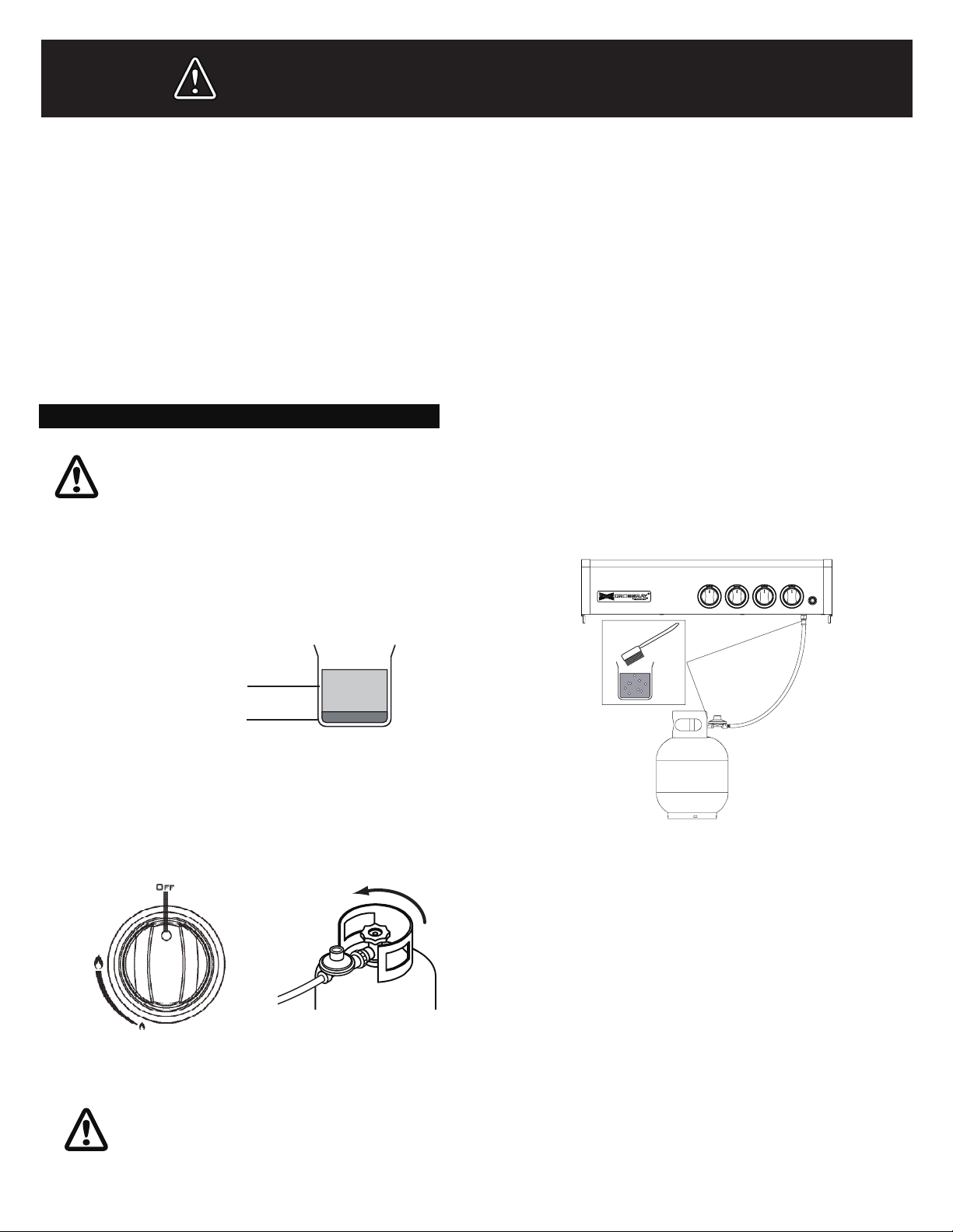
CHECKING FOR GAS LEAKS
CHECKING FOR GAS LEAKS
NEVER CHECK FOR LEAKS WITH
A FLAME.
Make liquid detergent solution by mixing one (1) part 1.
liquid detergent and four (4) parts water.
4 parts water
1 part liquid
detergent
Turn burner control knob(s) to "OFF", then turn on gas 2.
at source.
Open
3. Apply the liquid detergent solution to all visible and accessible gas connections, including the connection to the
gas cylinder. Bubbles will appear in the liquid detergent
solution if connections are not properly sealed. Tighten or
rectify as necessary.
Note:
This barbecue is approved for use on Natural
gas but must be properly converted from the
factory built LP. Contact your service agent
for details.
Conversion and installation must be by a
licensed plumber or gas fitter and comply
with local codes
IF YOU HAVE A GAS LEAK YOU CANNOT
RECTIFY, TURN OFF THE GAS AT THE
SO UR CE . CO N TA C T T H E S E R V IC E
AGENT
5
Page 6
OUTDOOR AREAS SAFE APPLIANCE LOCATIONS
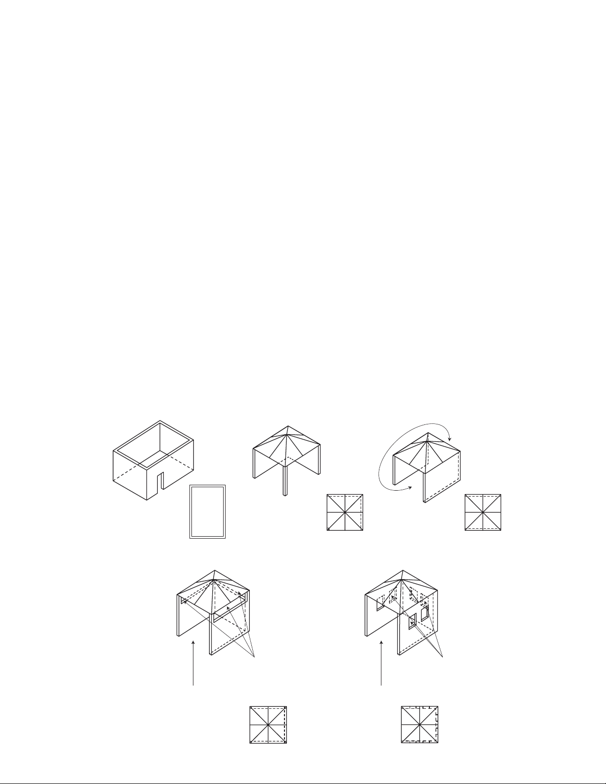
THIS APPLIANCE SHALL ONLY BE USED IN AN ABOVE GROUND OPEN AIR SITUATION WITH NATURAL VENTILATION, WITHOUT STAGNANT AREAS, WHERE GAS LEAKAGE AND PRODUCTS OF COMBUSTION ARE RAPIDLY DISPERSED BY WIND AND
NATURAL CONVECTION.
ANY ENCLOSURE IN WHICH THE APPLIANCE IS USED SHALL COMPLY WITH ONE OF THE FOLLOWING:
AN ENCLOSURE WITH •
WALLS ON ALL SIDES, BUT
AT LEAST ONE PERMA-
NENT OPENING AT GROUND
LEVEL AND NO OVERHEAD
COVER
WITHIN A PARTIAL• ENCLOSURE THAT INCLUDES AN
OVERHEAD COVER AND NO
MORE THAN TWO WALLS
WITHIN A PARTIAL ENCLO-•
SURE THAT INCLUDES AN
OVERHEAD COVER AND
MORE THAN TWO WALLS,
THE FOLLOWING SHALL APPLY:
The following diagrams are examples of outdoor areas.
These same principles apply to canopy or shaded cloth areas.
(i) AT LEAST 25% OF THE
TOTAL WALL AREA IS
COMPLETELY OPEN: AND
(ii) AT LEAST 30% OF THE
REMAINING WALL AREA IS
OPEN AND UNRESTRICTED
IN THE CASE OF BALCO-•
NIES, AT LEAST 20% OF THE
TOTAL OF THE SIDE, BACK
AND FRONT WALL AREAS
SHALL BE AND REMAIN
OPEN AND UNRESTRICTED
DO NOT USE YOUR BARBE-•
CUE IN GARAGES, PORCHES, BREEZEWAYS, SHEDS
OR OTHER ENCLOSED
AREAS.
YOUR BARBECUE IS TO BE
USED OUTDOORS ONLY.
Refer below
THE BARBECUE IS NOT IN-•
TENDED TO BE INSTALLED
IN OR USED ON RECREATIONAL VEHICLES AND/OR
BOATS AND SHOULD NOT
BE PLACED ADJACENT TO
OR UNDER ANY SURFACE
THAT WILL BURN
DO NOT OBSTRUCT THE •
FLOW OF COMBUSTION
AND VENTILATION AIR
AROUND THE BARBECUE
HOUSING WHILST IN USE.
Open side at
least 25% of
total wall area
30% or more in total
of the remaining
wall area is open
and unrestricted
6
Open side at
least 25% of
total wall area
30% or more in total
of the remaining
wall area is open
and unrestricted
Page 7
ASSEMBLY
GENERAL CHECK BARBECUE FOR ANY DAMAGE
While it is possible for one person to assemble the barbecue, we recommend asking for the assistance of another
person when manoeuvring some of the larger or heavier
pieces.
ASSEMBLY TIPS
Flatten cardboard packaging and use this as a 1.
protective work surface to assemble upon.
Some protective coating may need to be removed from 2.
components prior to assembly.
TOOLS YOU WILL NEED
Standard Phillips-head screwdriver.
Adjustable spanner (open end shifter).
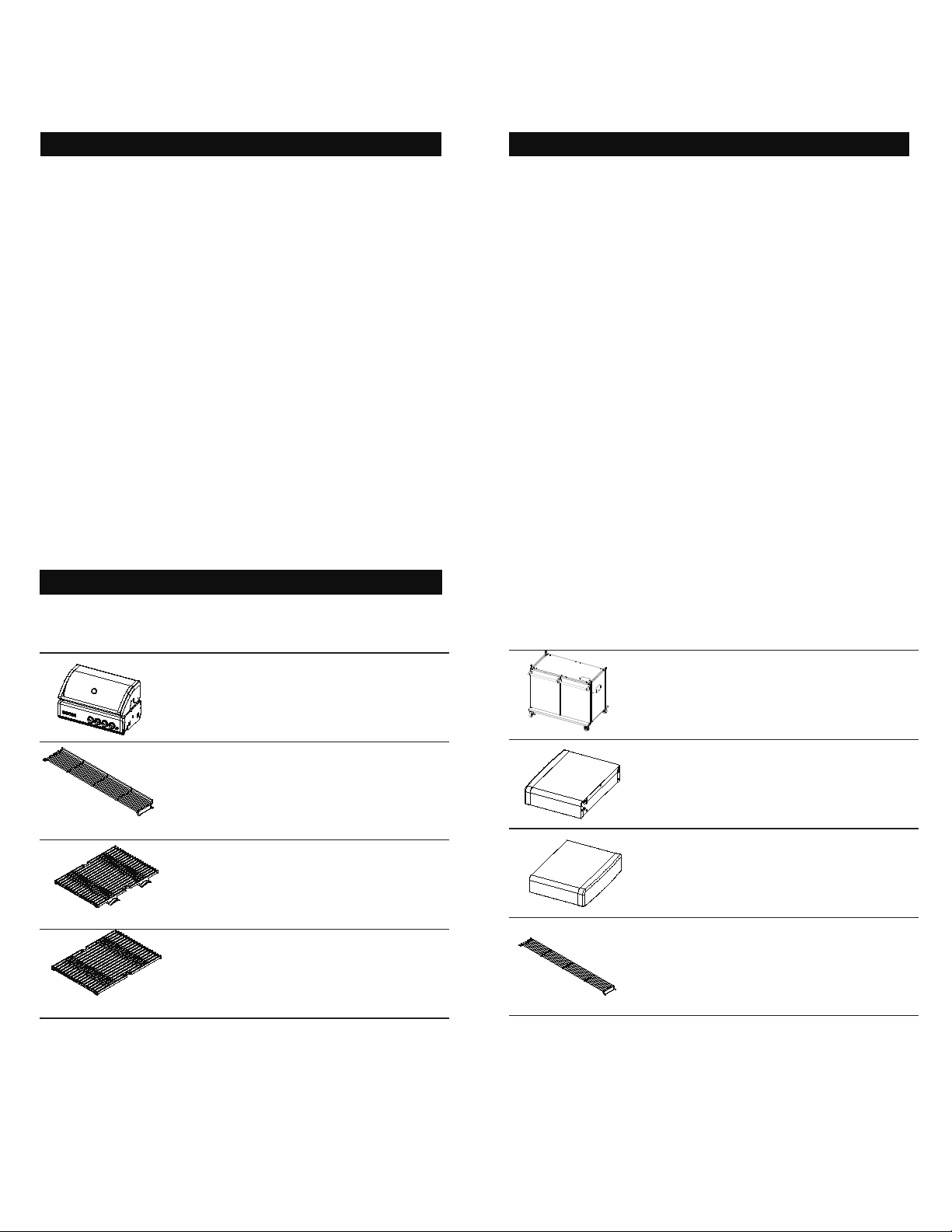
CARTON CONTENTS LIST
CHECK BARBECUE FOR ANY DAMAGE
Before attempting to assemble your barbecue, remove
transit protection and check that all the necessary parts
have been included using the parts list below. Inspect
barbecue and trolley parts as you proceed.
Contact your place of purchase for assistance
regarding replacement of any damaged or missing parts.
Supplier contact details are on the back cover of the
instruction manual.
Do not assemble or operate a barbecue that appears
damaged.
Check that the barbecue supplied is correct for the
gas type being used. There is a label on the side panel of
the barbecue above the gas connection. Barbecues for
"Propane" or "Universal LPG". Barbecues for use with
natural gas are labelled "Natural Gas".
DESCRIPTION QTY
BBQ Body Assembly 1
Upper Cooking Rack
(Large)
Cooking Grid 2
Cooking Grid 1
DESCRIPTION QTY
Trolley Assembly 1
1
Side Shelf, Left 1
Side Shelf, Right 1
Upper Cooking Rack
(Small)
1
7
Page 8
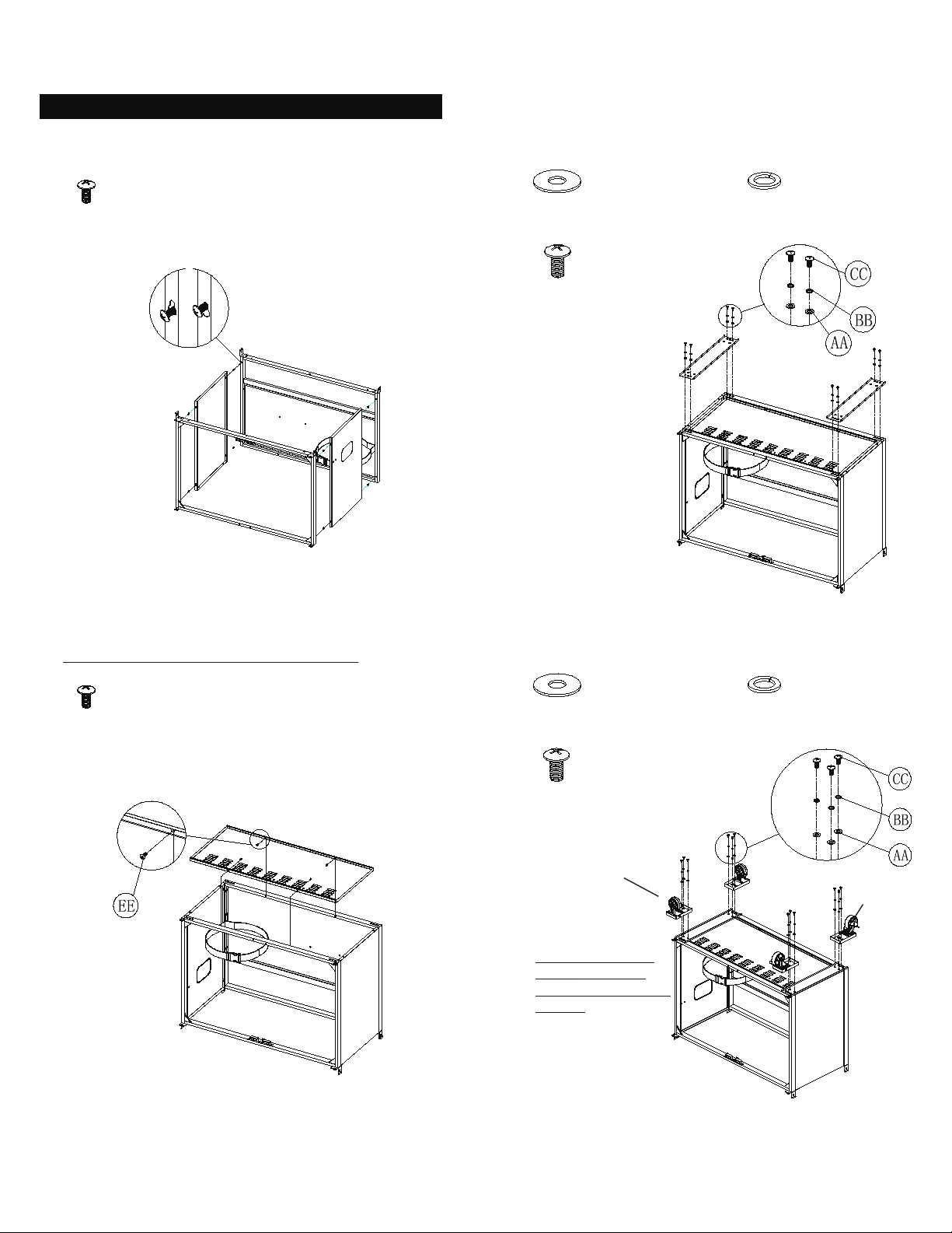
ASSEMBLY
Model: TCS4PL / TCS2PL
1. Assemble the Trolley Side Panels 3. Attach the Caster Seats
Phillips Head Screw
M4x12
Qty.8
EE
Part # S112M04121
AA
CC
Plain Washer
Qty. 8
Part # S411M06161
Phillips Head Screw
M6X15
Qty. 8
Part # S112M06151
Spring Washer
Qty. 8
BB
Part # S431M06091
2. Assemble the Trolley Bottom Panel 4. Attach the Casters
Note: take the trolley upside down
Phillips Head Screw
M4x12
Qty.4
EE
Part # S112M04121
AA
CC
Note: install each
caster to correct
place, as the Sticker
shown.
LF - Left Front
LR - Left Rear
RF - Right Front
RR - Right Rear
Plain Washer
Qty. 12
Part # S411M06161
Phillips Head Screw
M6X15
Qty. 12
Part # S112M06151
Caster without
Brake
Spring Washer
Qty. 12
BB
Part # S431M06091
Caster with
Brake
8
Page 9
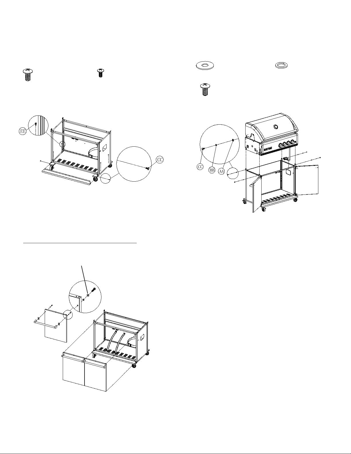
ASSEMBLY
5. Attach Trolley top panel and trim panel 7. Install Grill Head
CC
Phillips Head Screw
M6X15
Qty. 2
Part # S112M06151
Phillips Head Screw
M4x12
Qty.4
EE
Part # S112M04121
AA
CC
Plain Washer
Qty. 4
Part # S411M06161
Phillips Head Screw
M6X15
Qty. 4
Part # S112M06151
Spring Washer
Qty. 4
BB
Part # S431M06091
6. Install the Left and Right Doors
NOTE: ONE DOOR ONLY FOR MODEL: TCS2PL
Pre-assemblyscrews
9
Page 10
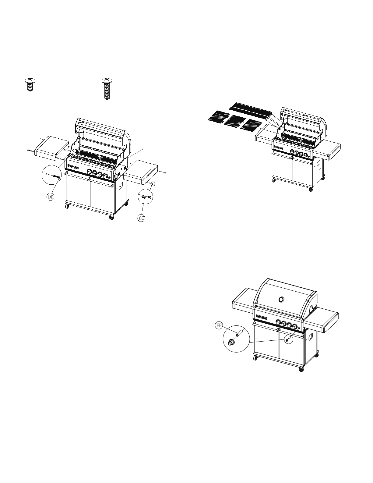
ASSEMBLY
8. Install the Left and Right Side Shelves 9. Install the Cooking Grids, Warming
Racks
Phillips Head Screw
M6x15
Qty.6
CC
Part # S112M06151
Phillips Head Screw
M6X35
Qty. 2
Part # S112M06351
DD
Pre-assembly
Screw
10. Install the Battery
10
Page 11
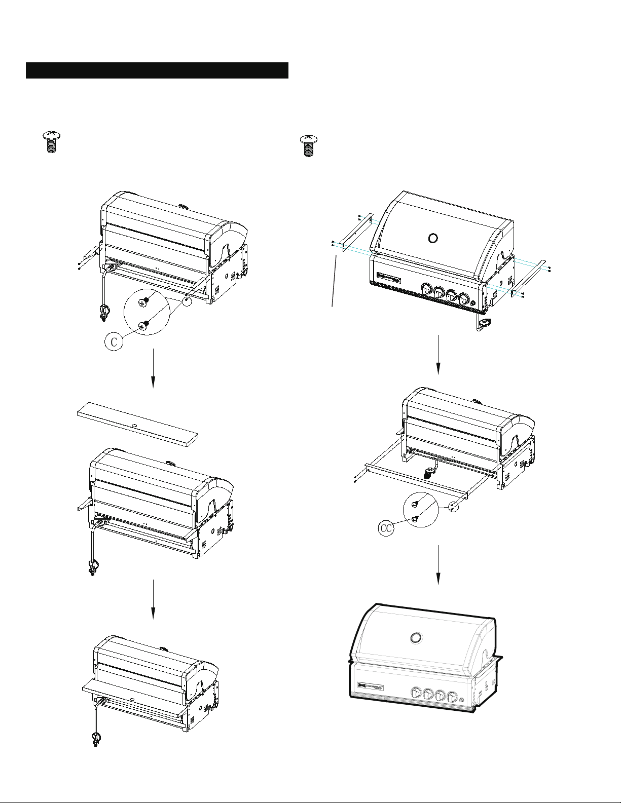
ASSEMBLY
Model: TCS4FL / TCS2FL
1. Install Trim Brackets (Optional trim brackets assembly instruction)
TCS4AC-009: Y0400049 TCR-FRAME : Y0400046
Phillips Head Screw
M6X15
Qty. 4
Part # S112M06151
Phillips Head Screw
M6X15
Qty. 12
Part # S112M06151
Pre - assembled
Screws
11
Page 12
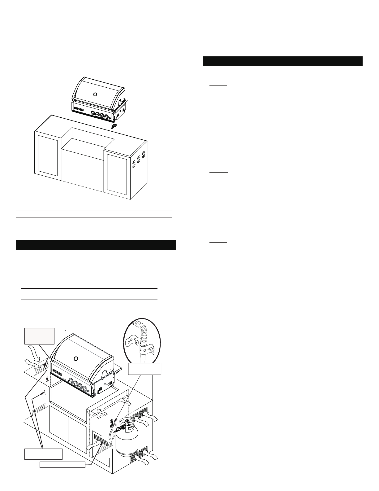
ASSEMBLY
2. Install the Grill Head
Note: the above illustration is for example only. All aspects
of the Installation shall be In compliance with AS / NZS 5601.
Including housing of the gas cylinder.
MOUNTING CUT - OUT
PRECAUTIONS
NOTE: When using Propane, EXTREME CAUTION should
be used to provide ample ventilation of vapor from the
enclosure.
LP Gas vapor is heavier than air and SERIOUS INJURY
from a DANGEROUS EXPLOSION could occur if LP Gas
is allowed to accumulate in an enclosure and then ignited.
Both the Barbecue enclosure and LP cylinder enclosure
require venting that must be provided at the oor level of
the enclosure to allow any leaking LP Gas vapor to escape.
Upper & lower ground-level vents (200 cm2)minimum
each) MUST BE PROVIDED on both sides of built-in
construction.
NOTE: When installing a barbecue equipped for liquid
propane in an isl and, the propan e ta nk m ust be in a
separate enclosure that is completely isolated from the
barbecue. It must be cross-ventilated in accordance with
the current standard. The propane tank MUST NEVER
be installed directly under the barbecue. NOTE: Upper &
lower ground-level vents (200 cm2) minimum each) MUST
BE PROVIDED for combustion air on both sides of built-in
construction.
NOTE: Do not use your grill in bad weather.
Refer to below for the minimum Cut out size
when designing the island unit.
Model
TCS4FL 928mm 260mm 608mm
TCS2FL 638mm 260mm 608mm
Vented on
Both Sides
of Island
Width Height Depth
Clamp down
flexline
Non-combustible
Contruction
Vented Access Door
12
Page 13
ENSURING BURNER CONTROLS ARE OFF
ENSURING BURNER CONTROLS ARE OFF
DISCONNECTING FROM GAS SOURCE
DISCONNECTING FROM GAS SOURCE
IMPORTA N T: Before connec t i n g and disconn e c t i n g
barbecue to gas source, ensure burner controls are in ‘OFF’
position.
NOTE: The ‘OFF’ position on the control panel is identied
by either a small black dot / a short vertical black line / or
the word ‘OFF’.
CAUTION: When the appliance is not in use, the gas must
be turned off at the gas cylinder.
Familiarise yourself with the general information and safety
guidelines located at the front of this booklet. Check to
see that gas cylinder is lled and that end of each burner
tube is properly located over each valve orice. Set burner
controls to ‘OFF’ position.
CONNECTING TO AND DISCONNECTING FROM GAS
SOURCE
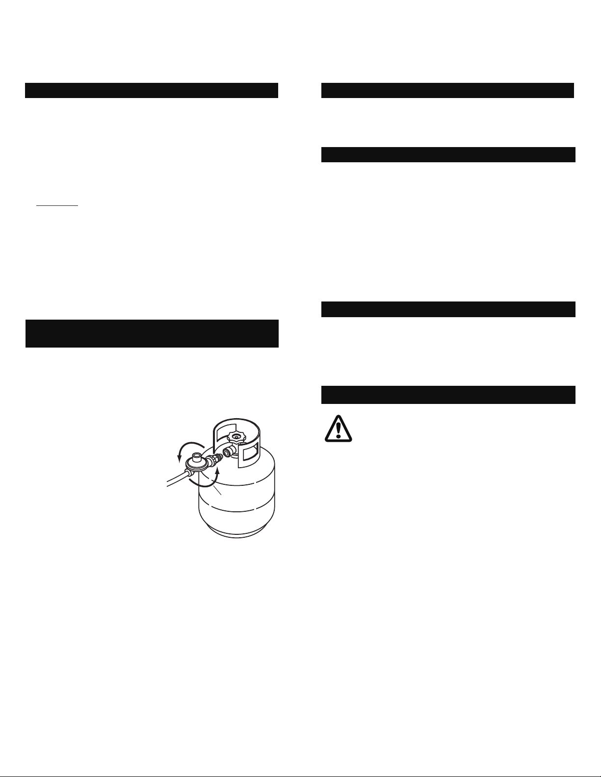
TO GAS SOURCE
Locate the gas cylinder in the cabinet and secure.1.
Attach the regulator and hose assembly to cylinder 2.
valve outlet. Tighten rmly.
Open the gas cylinder valve fully to allow gas to ow.3.
Leak test all 4. accessible connections thoroughly using a
soapy water solution prior
to lighting the barbecue.
Refer to Safety information,
page 5.
If a leak is found, turn gas 5.
cylinder valve off and recheck all connections have
been tightened. If there
is still a leak do not use
barbecue until repairs or
replacement can be made.
Direction for
tightening
Turn the burner controls ‘OFF’ .1.
Turn the gas cylinder valve off fully.2.
Detach the regulator assembly from gas cylinder valve.3.
NOW YOUR BARBECUE IS READY TO USE
NOW YOUR BARBECUE IS READY TO USE
Before first use and at the beginning of each barbecue
season:
Please read Safety, Lighting and Operating instructions 1.
carefully.
Check gas valve orices, burner tubes and burner ports 2.
for any obstructions. eg. spiders, webs, insects.
Check and ensure the gas cylinder is full.3.
Ensure all connections are securely tightened. Check 4.
for gas leaks.
CONNECTION TO A FIXED GAS SUPPLY
CONNECTION TO A FIXED GAS SUPPLY
When connecting to a xed gas supply the installation must
be in compliance with AS/NZS5601.
IMPORTANT
Before connecting and disconnecting barbe-•
cue to gas source, make sure burner controls
are in “OFF” position.
When the barbecue is not in use, the gas must •
be turned off at the cylinder.
The appliance control knob must be in the •
“OFF” position before opening the cylinder
valve.
Disconnect and remove gas cylinder when •
manoeuvring the barbecue over uneven
surfaces or carrying up and down stairs.
Check that the seals between the appliance •
and the gas cylinder are in place and in good
condition before connecting the gas cylinder.
Do not use this appliance if it has damaged or •
worn seals.
13
Page 14
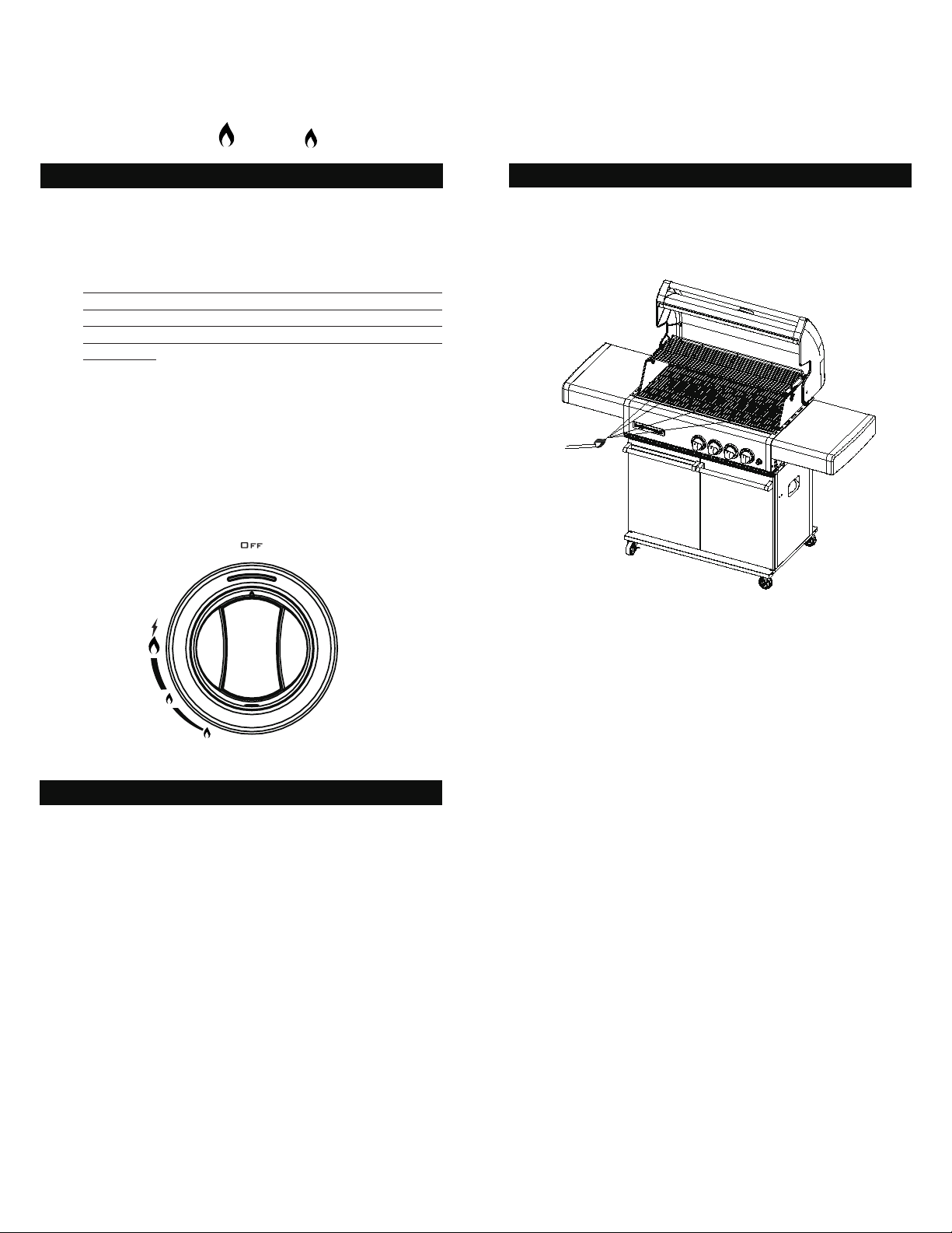
OPERATING PROCEDURE
SYMBOLS: HIGH LOW
BURNER IGNITION
Open barbecue hood before attempting to light 1.
burners.
Set burner control knobs to "OFF" and open the gas 2.
cylinder valve.
NOTE: Upon first assembly the gas lines and burners
will be full of air. In order for the burners to light
properly the lines must fill with gas. It may require
several attempts at lighting the burners before you are
successful.
3. Push and turn the required burner control knob to "HI".
4. Immediately press the Electric Ignition Button for up to
15 seconds to light the burner.
5. If the burner does not light, turn the burner control knob
to "OFF", wait 5 minutes for gas to clear, then retry.
6. Once the burner is ignited, adjust burner control knobs
to your desired cooking temperature.
7. If ignition cannot be achieved. Refer to "FAULT
FINDING"on page 16
LIGHT BARBECUE WITH MATCH
If for some reason, igniters fail to produce a spark at the
electrode, barbecue can be lit carefully with a match.
Remove the hotplate/grills plates light the burner with a
match.
NG
LPG
IMPORTANT
If • burners fail to light or go out during operation close
gas supply.
Open hood and wait 5 minutes before re-attempting to •
light (Ensure accumulated gas fumes have cleared).
Should a grease re occur, attempt to close gas supply •
at source, turn off all burners and remove food if
possible.
The hood must be in the open position for lighting.•
Do not smoke when attempting to ignite barbecue.•
Never use volcanic rock,• Heat beads or other material.
Always use protective gloves when handling hot •
components.
Keep the ventilation openings of the cylinder enclosure •
free and clear from debris.
Do not move trolley while barbecue is in operation.•
Ensure no pa cki ng mater ial is left i n BBQ b efo re •
lighting appliance.
14
Page 15

FAULT FINDING
IF THE BARBECUE FAILS TO LIGHT
FLOW OF GAS SEEMS ABNORMAL
FLOW OF GAS SEEMS ABNORMAL
Turn gas off at source and turn burner control knobs 1.
to ‘OFF’. Wait at least ve (5) minutes for gas to clear,
then retry.
If your barbecue still fails to light, check gas supply 2.
and connections.
Repeat lighting procedure. If your barbecue still fails 3.
to operate, turn the gas off at source, turn the control
knobs to‘OFF’, then check the following:
Obstruction in gas line•
Correction: Remove fuel line from barbecue. Do
not smoke! Open gas supply for one second to
clear any obst ruction from fuel line. C lose off
gas supply at source and reconnect fuel line to
barbecue.
Plugged orice•
Correction:Remove burners from barbecue.
Carefully lift each burner up and away from gas
valve orifice. Remove the orifice from gas valve
and gently clear any obstruction with a ne wire.
Then reinstall all orifices, burners, and cooking
components. If an obstruction is suspected in gas
valves or manifold contact your place of purchase
or service agent.
Disconnected electronic wires•
Correction: Inspect the igniter junction box found
behind the control panel. Connect loose electronic
wires to junction box and try to light the barbecue.
Check that gas cylinder is not empty.1.
Burner holes are dirty and clogged.2.
Gas regulator is not working.3.
SMELL OF GAS
SMELL OF GAS
Gas valve is open.1.
Gas hose is leaking (Check with soapy water)2.
Ga s hose is ben t or da m aged or not pos i tione d 3.
properly.
COOKER SMOKES
Burnings of oils and fats left behind (oils & fats must be
cleared off from oven after cooking).
Weak AA battery•
Correction: Unscrew the igniter cap and replace the
battery.
IMPORTANT
IMPORTANT
Should a ashback re occur in or around the burner •
tubes, follow the instruction below. Failure to comply
with these instructions could result in a re or explo-
sion that could cause serious bodily injury, death, or
property damage.
Shut off gas supply to the gas barbecue.•
Turn the control knobs to off position.•
Open the barbecue hood. Put out any ame with a re •
extinguisher.
Once the barbecue has cooled down, clean the burner •
tubes and burners.
15
Page 16

CARE & MAINTENANCE
As with all appliances, proper care and maintenance will keep
them in top operating condition and prolong their life. Your
new gas barbecue is no exception. By following these clean-
ing procedures on a timely basis, your barbecue will be kept
clean and working properly with minimum effort.
FLASH-BACK
FLASH-BACK
Spiders and small insects occasionally spin webs or make
nests in the burner tubes during warehousing and transit.
These webs can lead to a gas ow obstruction which could
result in a re in and around the burner tubes. Cleaning with
a soft brush before use and at least every six months is
recommended.
This type of re is known as ‘FLASH-BACK’ and can cause
serious damage to your barbecue and create an unsafe
operating condition for the user. Although an obstructed
burner tube is not the only cause of ‘FLASH-BACK’ it is the
most common cause and frequent inspection and cleaning
of the burner tubes is necessary.
If re occurs in and around the burner, immediately turn off
gas at its source and turn the burner control to‘OFF’, wait
until the barbecue has cooled, then clean the burner tubes
and burner ports.
CARE OF COOKING SURFACE
CARE OF COOKING SURFACE
Your barbecue is supplied with an enamel grill and plate.
Correct use and care of the cooking surface is important to
ensure trouble free cooking. Clean thoroughly while cooking
surface is cooling. Do not leave fo od on the cooking
surface when not in use.
CARE OF STAINLESS STEEL
CARE OF STAINLESS STEEL
Refer to Page 18 for details.
SERVICE
If the appliance cannot be adjusted to perform correctly it
should not be used until serviced or contact Focus Lifestyle
Products of
for service enquires.
(03) 9562 3455
or
info@thermolm.com.au
CLEANING THE GREASE TRAY
To avoid fat or grease dripping from the barbecue remove
and empty the drip tray after each use. A small amount of
water can be placed in the drip tray before use to help with
fat removal. Wait until the drip tray is cool to touch before
disposing of contents The drip tray should be washed
periodically in a mild detergent and warm water solution.
WARNING
To avoid any are-ups, it is recommended that the drip •
tray be checked and emptied regularly. Contents of the
drip tray may be very hot during cooking. If emptied
during extended cooking extreme caution should be
taken and direct contact by hand should be avoided at
all times. Allow to cool completely before disposing of
the contents.
Beware of spiders and wasps. Burner • tubes should be
inspected and cleaned periodically.
This appliance must only be serviced by an authorised •
person.
16
Page 17

CARE AND CLEANING OF STAINLESS STEEL
Stainless steel parts of this appliance are made from 304
grade stainless steel. To preserve the appearance and corrosion resistance of the stainless steel material regular
cleaning is required.
Although stainless steel does not rust in the same manner
as steel it can still exhibit ‘corrosion’ blemishes that look
similar to rust and detract from the appliances appearance.
Unlike steel, the corrosion of stainless steel is mostly
conned to the surface and in most cases can be removed
by cleaning, returning the surface to almost like new.
The most common form of corrosion that affects stainless
steel is what is known as ‘Tea Staining”. This shows up
as brown spots on the surface, hence the confusion
with rusting. This is most common in coastal areas
but depending on the environment can also occur in
inland areas. If the ‘Tea Staining’ marks are not regularly
cleaned from the material surface they can penetrate
into the material and become very difcult to remove, the
application of a metal polish would then be required.
If the appliance is located near swimming pools careful
attention to cleaning is required. Pool chemicals contain
chlorides which can affect the stainless steel. This also
applies to salt water pools as they contain salt, namely
sodium chloride.
The use of bleaches containing chlorine should not be used
to clean the stainless steel surfaces. If the residues are not
completed rinsed away they can cause heavy pitting of the
material. Pitting corrosion eats deep into the surface and is
not easily removed. Heavy polishing is required.
ROUTINE CARE
After each use allow the appliance to cool then wipe over
with a soft, damp, soapy cloth. (DO NOT USE CLEANERS
CONTAINING CHLORINE). Be sure to wipe off food particles
and cooking residues, some marinades and oils can be
acidic and therefore attack the metal surface. Also, cooking
residues that are not removed after each use bake into
the surfaces during subsequent uses and become more
difcult to remove.
There are a number of primary stainless steel cleaners
available that can be safely used on this appliance. Read
the directions carefully before using
DO NOT US E ST EEL WOO L as partic les can bec ome
embedded in the surface and then rust resulting in small
brown specs on the surface. If scouring is required to
remove stubborn cooking residues use a soft nylon pad (non
abrasive).
DO NOT USE ABRASIVE CLEANING COMPOUNDS, use
cream type.
If the appliance is used on an irregular basis it is advised to
still clean regularly and keep it covered from the elements,
either by using a durable BBQ cover or under a covered
porch. Dirt and dust contain corrosive particles from the
environment that can attack the surface. Stainless steel
surfaces retain their best resistance to corrosion when kept
clean. Even if the appliance is protected with a durable
BBQ cover check regularly, condensation underneath the
cover may be corrosive due to the local environment and
cause damage to the metal surface.
STUBBORN STAINS AND CORROSION SPOTS
STUBBORN STAINS AND CORROSION SPOTS
Stubborn stains, discolouration, ‘Tea Staining’ can occur
from insufcient cleaning, excessive spillage from cooking,
severe environmental conditions and extreme cooking
conditions.
There are proprietary stainless steel cleaners available that
are designed for such instances. Read the instructions
carefully before using.
Always rub or wipe in the direction of the surface grain or
original polish lines.
Some stainless steel cleaners may damage painted or
plastic surfaces, read the directions carefully.
After cleaning applying a thin coating of ‘light oil’, for
example baby oil, will also help protect the stainless steel
surface from the elements.
17
Page 18
MAINTENANCE
CLEANING THE BURNER TUBES AND BURNER PORTS
To reduce the chance of FLASHBACK FIRE you must
clean the burner tubes as follows at least once a month
in summer and fall or whenever spiders are active in
your area, and if your barbecue has not been used for an
extended period of time.
Turn all burner valves to the full "OFF" position.1.
Turn the LP ga s cyl inder valv e to th e ful l "OF F " 2.
position.
Detach the LP gas regulator assembly from your gas 3.
barbecue.
Remove the cooking plates from your barbecue.4.
Remove the screw from the burner using a screwdriver.5.
Carefully lift each burner up and away from the gas 6.
valve orice.
Check and clean burner / venturi tubes for insects and 7.
insect nests. A clogged tube can lead to a re beneath
the barbecue.
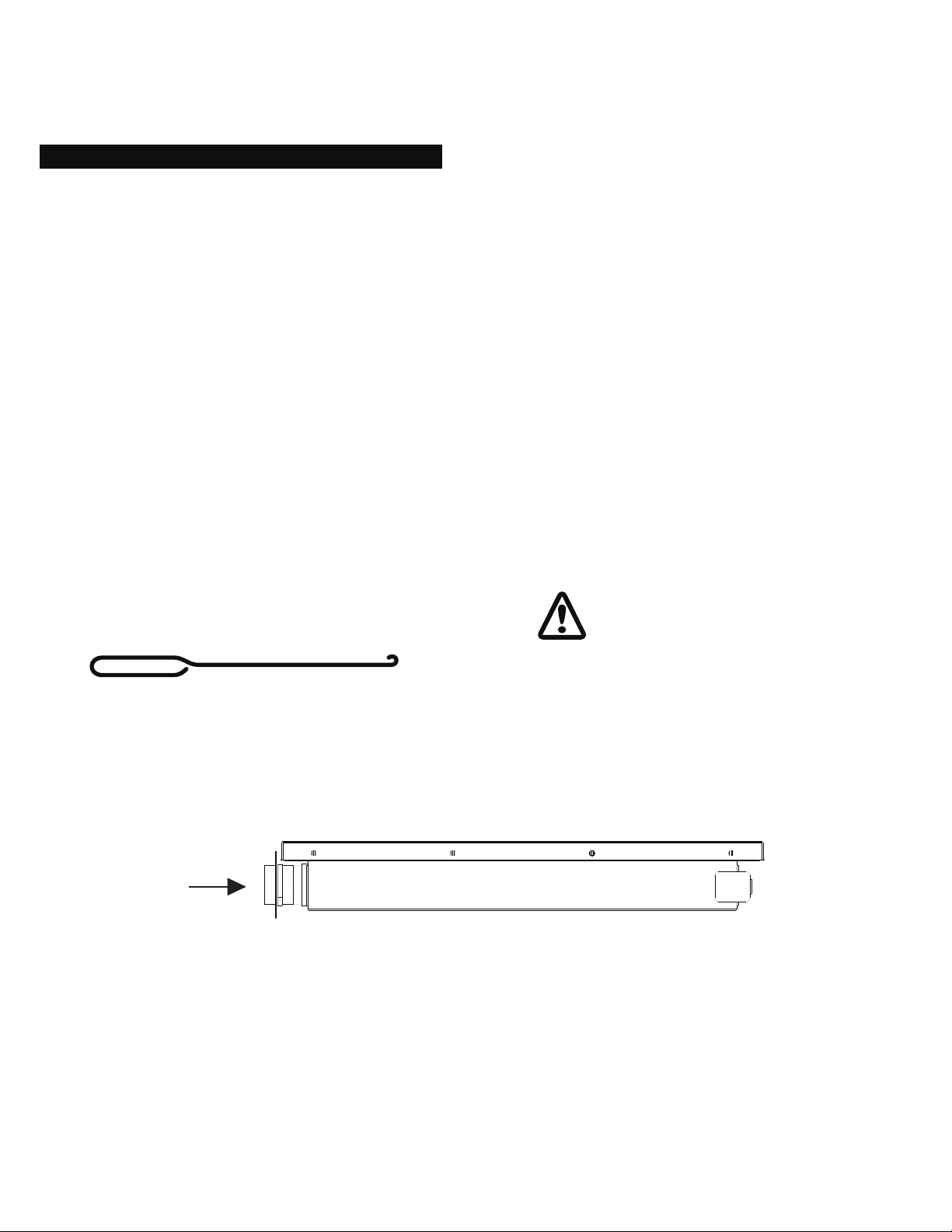
Refer to diagram 1 and perform one of these three 8.
cleaning methods:
METHOD 1: Bend a stiff wire or wire coat hanger into a small
hook as shown and run the hook through the burner tube and
inside the burner several times to remove debris.
Diagram 1
To clean burner tube, insert hook as indicated by the arrow.
METHOD 2: Use a bottle brush with a exible handle and run
the brush through the burner tube and inside the burner sev-
eral times to remove any debris.
METHOD 3: Use an air hose to force air through each burner
tube. The forced air should pass debris or obstructions
through the burner and out the ports. Regardless of which
burner cleaning procedure you use, we recommend you also
complete the following steps to help prolong burner life.
Use a fibre pad or nylon brush to clean the entire outer 1.
surface of each burner until free of food residue and dirt.
Clean any clogged ports with a stiff wire, such as an open 2.
paper clip.
Inspect each burner for damage (cracks or holes) and if 3.
such damage is found, order and install a new burner.
After installation, check to ensure that the gas valve
orices are correctly placed inside the ends of the burner
tubes. Also check the position of your spark electrode.
FO R SAF E OPE RATI ON EN SURE THE GAS
VALVE ASSEMBLY ORIFIC E IS INS IDE THE
B U R N E R T U B E B E F O R E U S I N G Y O UR
BARBECUE. IF THE ORIFICE IS NOT INSIDE
THE BURNER TUBE, LIGHTING THE BURNER
MAY CAUSE EXPLOSION AND / O R FIRE
RESULTING IN SERIOUS BODILY INJURY AND /
OR PROPERTY DAMAGE.
18
Page 19

19
Page 20
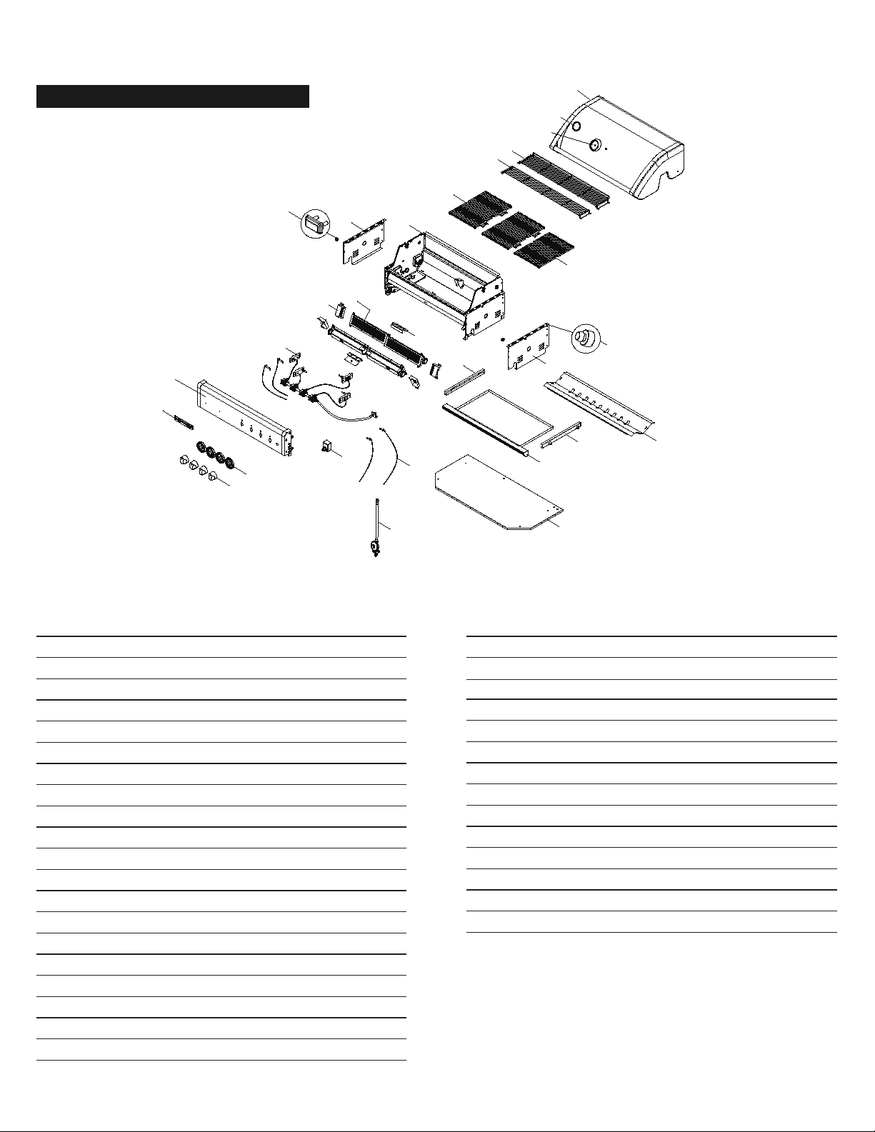
PARTS DIAGRAM
2
3
1
4
5
6A
6B
7
8
12A
9B
19
12B
10
11
13
14
15
22
16
17B
17A
20
18
9A
17C
17D
21
Model: TCS4FL & TCS4PL (Grill Head Only)
PARTS LIST
KEY DESCRIPTION PART# QTY
1 Hood Assembly P0014761KA 1
2 Temperature Gauge P00601601C 1
3 Temperature Gauge Seat P00614047E 1
4 Warming Rack D145 P01507035H 1
5 Warming Rack D100 P01507036H 1
6A Cooking Grid W281 P01615067H 1
6B Cooking Grid W295 P01615068H 2
7 Grill Bowl Assembly P00736057E 1
8A Burner/Main P020050364 4
8B Burner Wind Shield P06909009C 4
9 Gas Collector Box (cross lighter) P02212425A 2
10 Burner Bracket, Upper P02213477A 1
9C Gas Collector Box (cross lighter) P02212425A 2
10 Gas Valve/Manifold Assembly - AU/USA Y0060893 1
Main Burner Jet ( LPG ) P06526013A 4
Pilot Burner Jet ( LPG ) P06526014A 4
11 Electric Wires Set/Electrode P02614017A 1
12A Protective Pad P05518112K 2
12B Protective Pad P05518113K 2
13 Electric Ignitor, 4 ports P02502484F 1
KEY DESCRIPTION PART# QTY
14 Control Panel P02914481S 1
15 Control Knob Seat P03433014A 4
16 Control Knob P03444022V 4
17A Grease Tray Heat Shield P06904075C 1
17B Grease Tray P02706443C 1
17C Grease Receptacle P03319007C 1
17D Grease Receptacle Front Panel, Right P03319008C 1
18 Side Shelf Connecting Bracket, Left P01202009B 1
19 Side Shelf Connecting Bracket, Right P01203009B 1
20 Regulator with Hose (LPG) P03644005A 1
21 Bowl Bottom Shelf P010041005 1
22 Name Plates P00403009D 1
Plancha (Optional) P05701058B 1
Operator's Manual P80196010B 1
20
Page 21
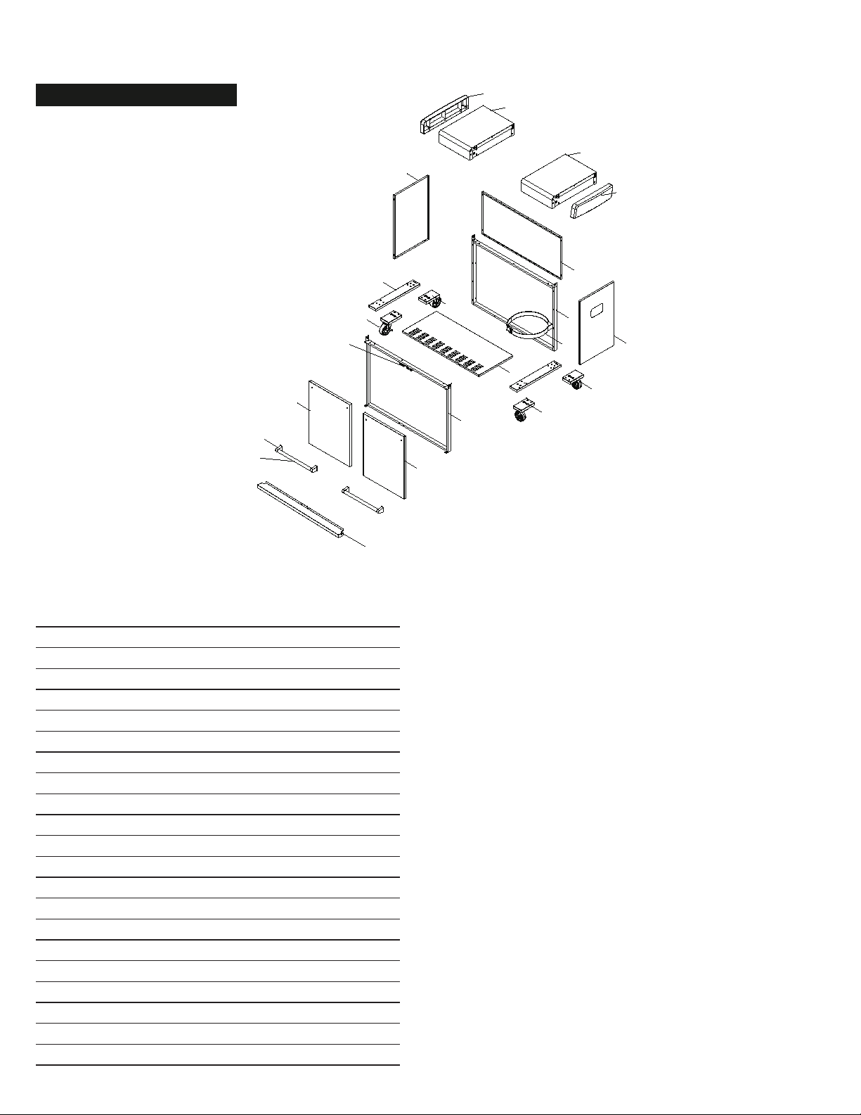
PARTS DIAGRAM
1
2
3
4
5
6
7
8
9
12
14A
13B
16
17
16
18
10
11
15
19
13A
14B
Model: TCS4PL (Trolley only)
PARTS LIST
KEY DESCRIPTION PART# QTY
1 Cart Panel, Left P07605049B 1
2 Cart Panel, Right P07606053B 1
3 Cart Panel, Rear P07624010B 1
4 Cart Panel, Bottom P01004096J 1
5 Cart Frame, Front P07201009B 1
6 Cart Frame, Rear P07201010B 1
7 Tank Fastening Strap (LPG) P05314016V 1
8 Cart Door, Left Y0410031 1
9 Cart Door, Right Y0410032 1
10 Handle Seat P00303222A 2
11 Door Handle P002051242 2
12 Caster Seat P05327075W 2
13A 3" Caster with Brake, Left Front P05112039A 1
13B 3" Caster with Brake, Left Rear P05112038A 1
14A 3" Caster without Brake, Right Front P05112041A 1
14B 3" Caster without Brake, Right Rear P05112040A 1
15 Trolley Trim Panel P07501022R 1
16 Side Shelf P01106055B 2
17 Side Shelf Cap, Left P01123002E 1
18 Side Shelf Cap, Right P01122002E 1
19 Magnet P05523058M 2
21
Page 22

WARRANTY
WARRANTY PROVISIONS
Thermolm has great condence in its products and offers excellent warranty provisions in addition to all rights and remedies to which
you may be entitled by law. For ‘Crossray’ barbecues, our additional warranty period applies for 2 years from the date of purchase. If
a manufacturing defect covered by our additional warranty becomes apparent within this period of 2 years then we guarantee that the
defective component will be replaced or repaired at no charge.
Subject to the below exclusions, our additional warranty offers:
• 2 year guarantee against damage to stainless steel components from rust-through
• 2 year guarantee against rust-through for parts nished in enamel
• 2 year guarantee against rust-through for coated parts
These benets operate alongside, and in addition to, the consumer guarantees to which you are entitled under the Australian Consumer
Law. Our goods come with guarantees that cannot be excluded under Australian Consumer Law. You are entitled to a replacement or
refund for a major failure and for compensation for any other reasonably foreseeable loss or damage. You are also entitled to have the
goods repaired or replaced if the goods fail to be of acceptable quality and the failure does not amount to a major failure.
ALL RIGHTS UNDER OUR ADDITIONAL WARRANTY BECOME NULL AND VOID IF:
• The product is not assembled and installed in accordance with the instructions
• The product is used improperly
• Scratches, dents, damage, discolouration etc. occur due to heat and aggressive cleansing agents
• The product is used for commercial purposes and / or is rented out
• The product suffers damage from the forces of nature
• Burn spots occur due to improper maintenance and / or cleaning of the grill
(for example due to grease / fat remaining behind and burning)
• The gas hose is not properly installed; if no leak test is performed as shown in Instruction manual
• The grill has been converted for use with natural gas; unless factory built or converted by Thermolm or converted by
an authorised person where the conversion kit has been supplied by Thermolm Products.
• The product is not being used in Australia.
• Damage is caused by a third party
THE FOLLOWING ARE EXCLUDED FROM OUR ADDITIONAL WARRANTY:
• Ignition batteries becoming at due to normal use.
• Peeling / separation of the coating as a result of grease / fat being burned in
• Peeling / separation of the paint / enamel and coating
• Light rust such as ash-rust
• Normal wear and tear resulting from usage
• Faults which do not noticeably affect the operation or value of the appliance
All warranty coverage excludes grill paint loss or rusting (except rust-through) which are either expendable parts that can wear out from
normal use in less than 2 years, or are conditions that can be the result of normal use, accident or improper installation or maintenance.
SPARE PARTS
Thermolm keep a large number of spare parts in stock in order to deal with claims quickly and effectively. However, if a spare part is
not in stock Thermolm reserves the right to send a similar part to resolve the problem.
Model of BBQ Part that requires replacement
Year of purchase
Your Contact Details
FOR CUSTOMER REFERENCE
(Record and le in a safe place)
Purchased from Receipt Number
Date purchased Serial No.
Model Name and Number
22
Page 23

CONNECTING NATURAL GAS
Contact a registered Gas Fitter/Plumber to obtain a quote for the conversion and to conrm whether this appliance will work ef-1.
ciently with the current gas supply to your household, in accordance with the Installation Code AS/NZS 5601.
The Gas Fitter/Plumber will need to source the necessary parts for the conversion. Note : Conversion Kits can be ordered directly 2.
from Thermolm Phone: (03) 9562 3455 Email: info@thermolm.com.au
Upon completion of the conversion, the Gas Fitter/Plumber is Legally required to issue a Compliance Certicate.3.
Do Not attempt to complete the conversion yourself.4.
Failure to comply with these requirements and Installation Code AS/NZS 5601 will automatically void the Warranty for this product.5.
23
 Loading...