

CROSSPOINT TECHNOLOGIES MS-400 SERIES Operating Manual

MS-400x Matrix Switch
Operating Manual
CPT-006-1410
Rev H
CrossPoint Technologies, Inc.
3 Foshay Road
Dudley, MA 01571
860-935-0284
CAGE: 3XJY8

Revision
Date
Summary of Changes
-
Original Issue
A
Jan 6, 2006
Added MS4001-4x4-LB-MW-P
B
June 19, 2006
Added MS-4001-32x32-HF, Ethernet
C
April 9, 2010
Added MS-4000-8x32-LB-FO, MS-4000-16x32-LB-FO, MS-400032x8-LB-FI, MS-4000-32x16-LB-FI
D
April 16, 2010
Added MS-4001-32x32-HF, Modifications to Firmware v1.9 to
Added MS-4001-32x32-HF Addendum.
E
Sept 24, 2010
Added MS-4000-8x8-LB-FO Addendum. Added MS-4000-8x8-LBFI Addendum.
F
August 28,
2012
Changing specs for Addendums regarding LB3 and Ethernet
additions. Added MS-4001-16X6-XB-FO addendum.
G
October 15,
2012
Removed Maximum Input Signal Spec from L Band Units. Added
1dB Compression Point of 0dBm Min.
H
October 3,
2016
Added Ethernet port and Ethernet functionality to the
MS-4001-12X6-KU-FO Switch section.
Revision History
CPT-006-1410

Rev H Model MS-400x
CrossPoint Technologies, Inc. makes no warranty of any kind with regard to this material,
including but not limited to, the implied warranties of merchantability and fitness for a particular
purpose. CrossPoint Technologies shall not be liable for errors contained herein or for incidental
or consequential damages in connection with the furnishing, performance, or use of this material.
All Rights Reserved. Reproduction, adaptation, or translation without prior written permission is
prohibited, except as allowed under the copyright laws.
The information contained in this document is subject to change without notice.
SAFETY CONSIDERATIONS
General
Before operating this product, you must review all related documentation for
familiarization with safety markings and instructions.
Safety Symbols and definitions
Operating Manual symbol. The product will be marked with this symbol when it
is necessary to refer to the Operating Manual.
Electrical Hazard Warning. The product will be marked with this symbol when
hazardous conditions such as high voltages could exist.
Protective Earth Ground. The product will be marked with this symbol at the location
of the earth ground terminal.
i

Rev H Model MS-400x
WARNING Warning denotes a hazard. It calls attention to a procedure which, if not correctly
performed or adhered to, could result in injury or loss of life. Do not proceed
beyond a warning note until the indicated conditions are fully understood and met.
CAUTION Caution denotes a hazard. It calls attention to a procedure that, if not correctly
performed or adhered to, could result in damage to or destruction of the
instrument. Do not proceed beyond a caution sign until the indicated conditions
are fully understood and met.
CAUTION Always use the three-prong AC power cords supplied with this product. Failure to
ensure adequate grounding may cause product damage. When adapting to
foreign AC mains connectors, a grounded line cord must be selected.
WARNING The mains plug shall be inserted only in a socket outlet provided with a protected
earth contact. Any interruption of the protective conductor inside or outside of the
product is likely to make the product dangerous. Intentional interruption is
prohibited.
WARNING No operator serviceable parts inside. Refer servicing to qualified personnel. To
prevent electrical shock do not remove covers.
WARNING Before this instrument is switched on, make sure it has been properly grounded
through the protective conductor of the ac power cable to a socket outlet provided
with protective earth contact.
WARNING There are many points in the instrument which can, if contacted, cause personal
injury. Be extremely careful. Any adjustments or service procedures that require
operation of the instrument with protective covers removed should be performed
only by trained service personnel
WARNING Any interruption of the protective (grounding) conductor, inside or outside the
instrument, or disconnection of the protective earth terminal can result in personal
injury.
WARNING If this instrument is used in a manner not specified by CrossPoint Technologies,
the protection provided by the instrument may be impaired.
CAUTION When removing a power supply drawer while the system is powered by the
alternate drawer (hot-swapping), the power switch must be turned to its Off (“O”)
position before removing the thumbscrews to release the power supply drawer.
Withdrawing a power supply while powered can damage the equipment.
CAUTION When inserting a power supply drawer while the system is powered by the
alternate drawer (hot-swapping), the power switch on the replacement power
supply must be turned to its Off (“O”) position before inserting the power supply
drawer. Inserting a power supply with its switch On (“1”) can damage the
equipment.
ii

Rev H Model MS-400x
Warranty
This CrossPoint Technologies product is warranted against defects in material and workmanship
for a period of one year from date of shipment. During the warranty period, CrossPoint
Technologies will, at its option, either repair or replace products that prove to be defective.
For warranty service or repair, this product must be returned to a service facility designated by
CrossPoint Technologies. Buyer shall prepay shipping charges to CrossPoint Technologies and
CrossPoint Technologies shall pay shipping charges to return the product to Buyer. However,
Buyer shall pay all shipping charges, duties, and taxes for products returned to CrossPoint
Technologies from another country.
CrossPoint Technologies warrants that its software and firmware designated by CrossPoint
Technologies for use with an instrument will execute its programming instructions when properly
installed on that instrument. CrossPoint Technologies does not warrant that the operation of the
instrument, or software, or firmware will be uninterrupted or error-free.
LIMITATION OF WARRANTY
The foregoing warranty shall not apply to defects resulting from improper or inadequate
maintenance by Buyer, Buyer-supplied software or interfacing, unauthorized modification or
misuse, operation outside of the environmental specifications for the product, or improper
site preparation or maintenance.
NO OTHER WARRANTY IS EXPRESSED OR IMPLIED. CROSSPOINT TECHNOLOGIES
SPECIFICALLY DISCLAIMS THE IMPLIED WARRANTIES OF MERCHANTABILITY AND
FITNESS FOR A PARTICULAR PURPOSE.
EXCLUSIVE REMEDIES
THE REMEDIES PROVIDED HEREIN ARE BUYER’S SOLE AND EXCLUSIVE REMEDIES.
CROSSPOINT TECHNOLOGIES SHALL NOT BE LIABLE FOR ANY DIRECT, INDIRECT,
SPECIAL, INCIDENTAL, OR CONSEQUENTIAL DAMAGES, WHETHER BASED ON
CONTRACT, TORT, OR ANY OTHER LEGAL THEORY.
iii

Rev H Model MS-400x
Table of Contents
1 Introduction ............................................................................................................................... 1
1.1 Applicability ........................................................................................................................ 1
1.2 Terminology ....................................................................................................................... 1
2 Controls and Indicators ............................................................................................................. 2
2.1 Front Panel ........................................................................................................................ 2
2.2 Rear Panel ........................................................................................................................ 3
3 Installation ................................................................................................................................ 3
3.1 Connections ...................................................................................................................... 3
3.1.1 AC Power ................................................................................................................... 3
3.1.2 Serial Port .................................................................................................................. 3
3.2 RS-422 Remote Control Operation ................................................................................... 4
4 Front Panel Operation .............................................................................................................. 6
4.1 Remote and Local Modes ................................................................................................. 6
4.2 Setting Switches ................................................................................................................ 6
4.3 Using the Menus ............................................................................................................... 7
4.4 LCD screens and Menus ................................................................................................... 7
4.4.1 Menu Tree .................................................................................................................. 7
4.4.2 Startup Splash ............................................................................................................ 8
4.4.3 Connection Screen..................................................................................................... 8
4.4.4 Remote/Local Control ................................................................................................ 9
4.4.5 Status ......................................................................................................................... 9
4.4.6 Maintenance & Setup ............................................................................................... 16
4.4.7 Set Defaults.............................................................................................................. 20
5 Remote Control ...................................................................................................................... 21
5.1 Interfaces......................................................................................................................... 21
5.2 Protocol ........................................................................................................................... 21
5.2.1 Summary .................................................................................................................. 22
5.2.2 Detailed Command and Status Formats .................................................................. 22
Appendix ........................................................................................................................................ 32
A. MS-4000-16x16-LB3-FO..................................................................................................... 33
B. MS-4000-16x16-LB3-FI ...................................................................................................... 38
C. MS -4000-32x32-IF-FO ........................................................................................................ 43
D. MS -4000-32x32-IF-FI.......................................................................................................... 49
E. MS-4001-10x6-XB-FO ........................................................................................................ 55
F. MS-4001-12x6-KU-FO............................................................................................................ 60
G. MS-4001-4x4-LB-MW-P ..................................................................................................... 65
H. MS-4001-32x32-HF ............................................................................................................ 70
I. MS-4000-8x32-LB-FO ............................................................................................................ 93
J. MS-4000-16x32-LB-FO .......................................................................................................... 99
K. MS-4000-32x8-LB-FI ........................................................................................................ 105
L. MS-4000-32x16-LB-FI .......................................................................................................... 111
M. MS-4000-8x8-LB3-FO....................................................................................................... 117
N. MS-4000-8x8-LB-FI .......................................................................................................... 120
O. MS-4001-16x6-XB-FO ...................................................................................................... 123
i

Rev H Model MS-400x
1 Introduction
CrossPoint Technologies Model MS-400x Matrix Switches are available in a variety of input/output
configurations. The operation and remote control interfaces are identical for all devices. The MS4000 series are solid state switches. The MS-4001 use mechanical RF relays as their switching
element. The chassis size varies with the complement of switches installed. Frequency range is
customer specified.
1.1 Applicability
This manual covers a family of Matrix Switches. The following models are included in this manual:
MS-4000-16x16-LB3-FO
MS-4000-16x16-LB3-FI
MS-4000-32x32-IF-FO
MS-4000-32x32-IF-FI
MS-4001-10x6-XB-FO
MS-4001-12x6-KU-FO
MS-4001-4x4-LB-MW-P
MS-4001-32x32-HF
MS-4000-8x32-LB-FO
MS-4000-16x32-LB-FO
MS-4000-32x8-LB-FI
MS-4000-32x16-LB-FI
MS-4000-8X8-LB3-FO
MS-4000-8X8-LB3-FI
MS-4001-16X6-XB-FO
Detailed specifications and additional information specific to each model are found in the
Appendix.
Other models are available for different frequency ranges or for different numbers of channels.
The MS-400x can be optimized to your application.
1.2 Terminology
Matrix switches are specified in one of two ways. If the matrix is designed as “full fan out”, each
input can be routed to all its outputs simultaneously. Each output has only one input at a time. If
the matrix is “full fan in”, each output can sum all inputs simultaneously. Each input can only be
assigned to a single output at a time.
These matrix configurations exhibit a “one to many” (fan out) or “many to one” (fan in)
characteristic. The internal configuration of these two architectures are often a mirror image of
one another.
CrossPoint Technologies, Inc 1
Rev H Model MS-400x
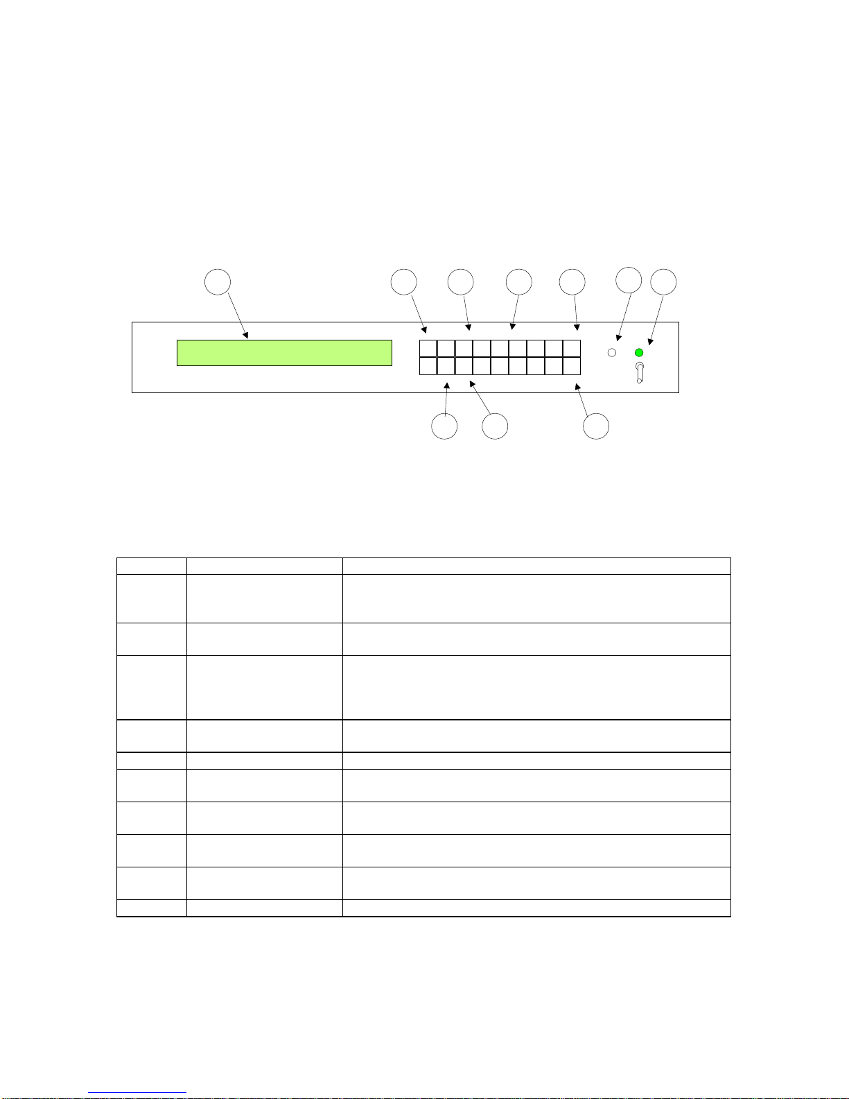
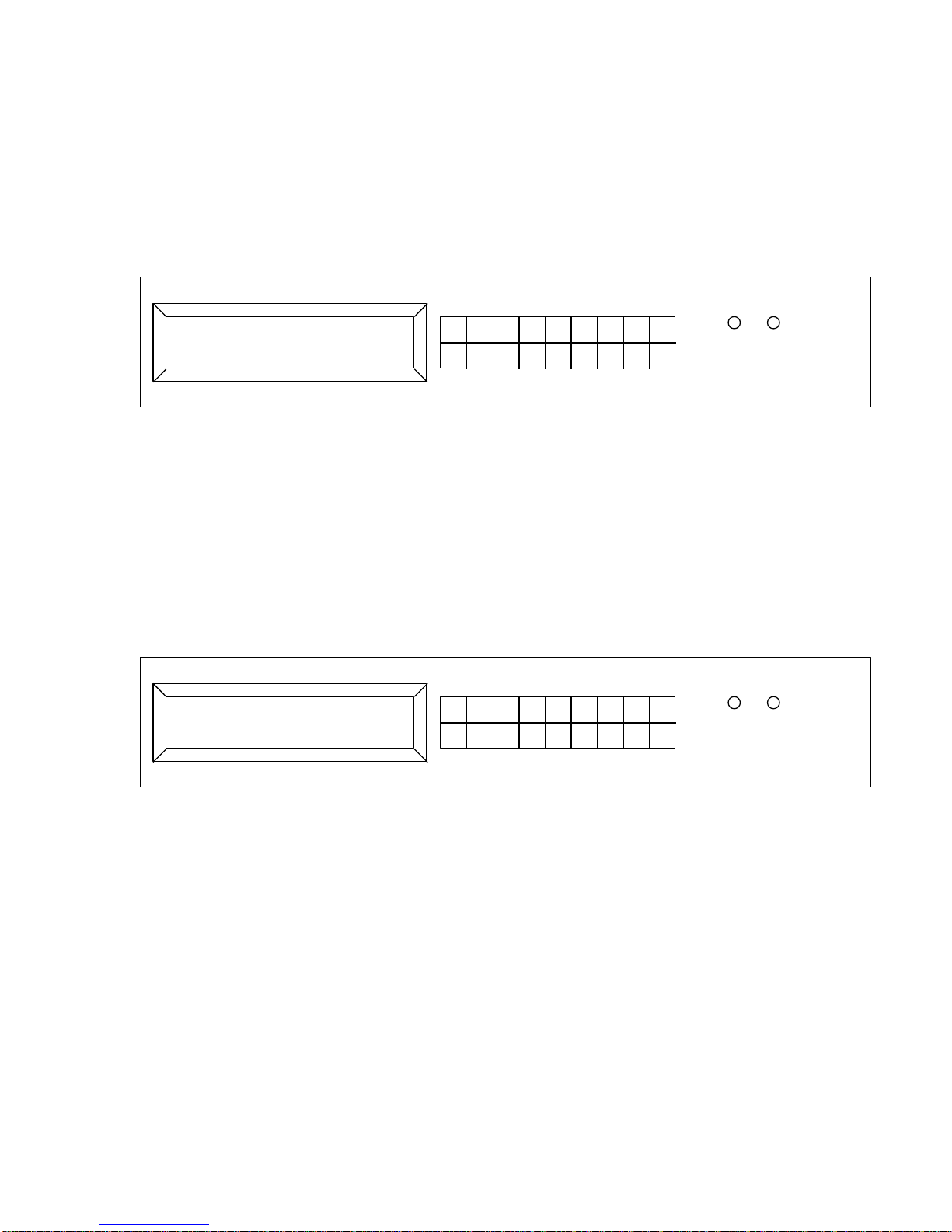
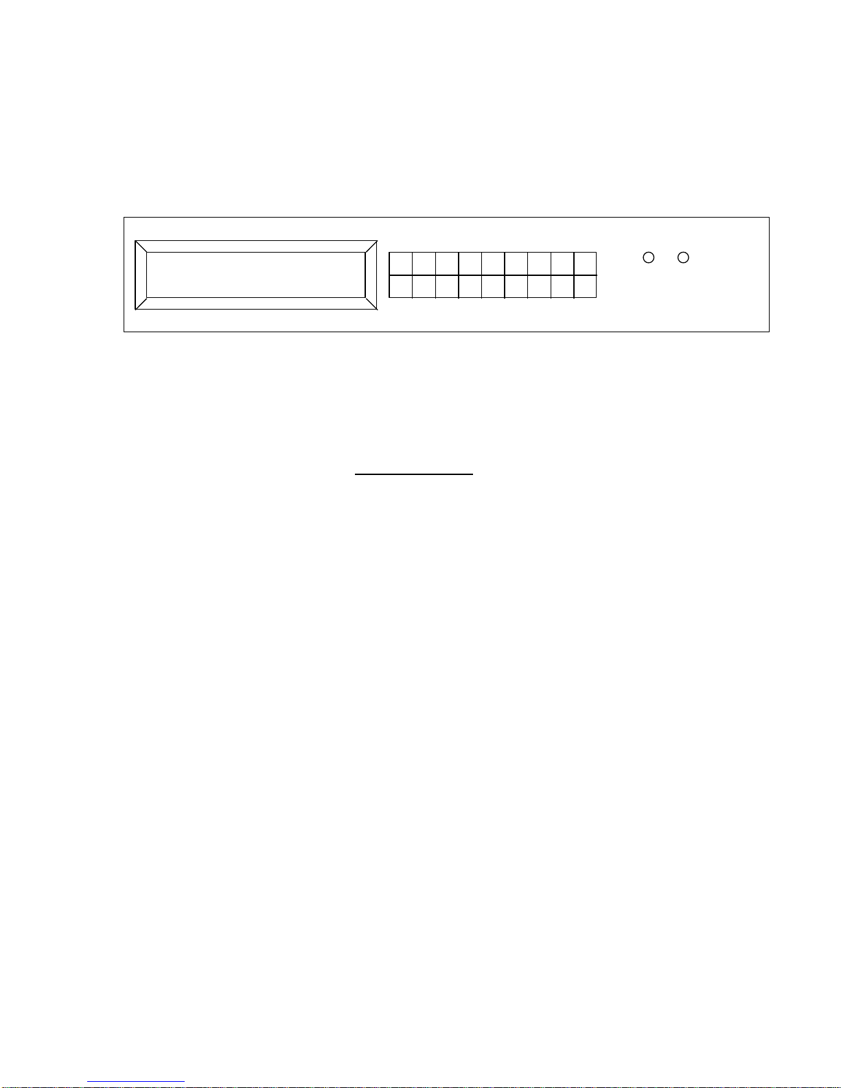
UP IN MENU 1 2 3 4 5 ESC
DN OUT OFF 6 7 8 9 0 ENT
LCD
FLT PS
1
2
3
4 6
5
7
9 810
Callout
Name
Description
1
POWER Indicator &
Power switch
Illuminated green when power is on. Turns Red if a power
supply problem is detected. Two LED’s are present when
there are redundant power supplies.
2
FAULT Indicator
Illuminated Red when any fault is detected in any chassis.
This is a summary alarm indication
3
UP and DOWN
Used to cycle through the list of available inputs or outputs
when in an Edit mode. Scrolls through Menu items when in
MENU mode Incrementing/Decrementing rolls over/under at
the extremes
4
IN and OUT
Press IN or OUT to enter the Edit mode, and change a
switch connection.
5
Numeric keys
Enter matrix port numbers directly using these keys.
6
OFF key
Used to disconnect an output. This key can be used in Edit
mode. Press Enter to accept the OFF (disconnect) condition.
7
ENTer key
Accept the current input or output, exit the Edit mode and
return to the next higher menu level.
8
ESCape key
Cancel the current Edit session and return to the next higher
menu level. No changes occur to matrix state.
9
MENU key
Move from the normal display to the various configuration
and status menus.
10
LCD Display
For local status and control.
2 Controls and Indicators
2.1 Front Panel
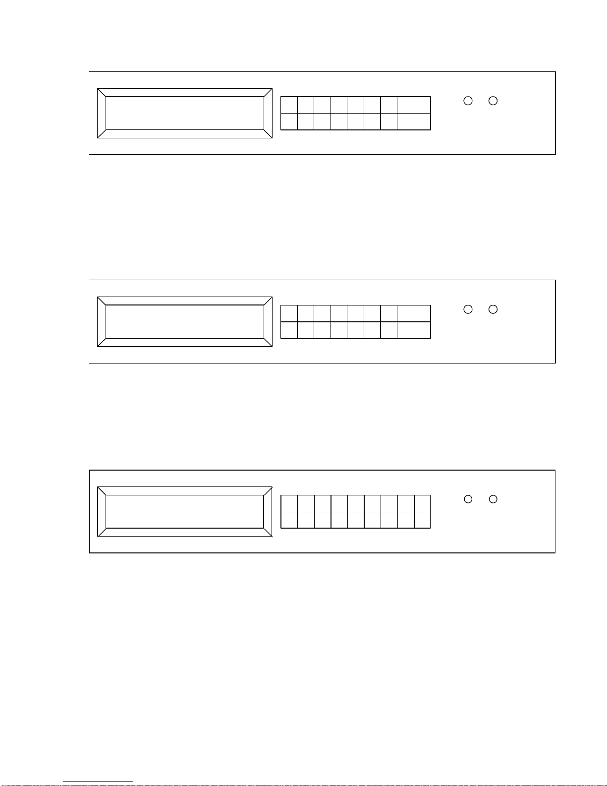
There may be different front panel heights, but the layout of the controls is always the same. The
1RU Matrix Controller front panel is shown here. All the indicators and controls are identified and
explained below. More details on how to use these controls may be found in Section 4.
Figure 1 : Front Panel Controls and Indicators
Front Panel Controls and Indicators
CrossPoint Technologies, Inc 2

Rev H Model MS-400x
2.2 Rear Panel
Rear panels are customized to the different matrix configurations. Specific drawings found in the
Appendix for each model that identify the connector reference numbers (“J numbers”).
3 Installation
The Matrix Switch mounts in a standard EIA rack. Internal fans provide cooling from side to side.
Standard rack mounting will allow adequate clearance for the air vents on the sides. The unit does
not require empty rack space above or below.
3.1 Connections
3.1.1 AC Power
The Matrix is provided with a standard detachable US AC line cord. However, the internal power
supplies have universal voltage capability (220/110 VAC). Plug the equipment into an AC source
of either 110 or 220 VAC.
3.1.2 Serial Port
The serial port is a dual purpose connector located on the rear of the Matrix. The connector is
labeled CTRL. It provides RS-232 format signals as well as RS-422 signals. The chassis
connector is a common 9 pin male D connector.
3.1.2.1 RS-232 Operation
RS-232 is recommended for cable lengths up to 50 feet between the computer and the matrix.
Longer links can be accommodated reliably, but may require experimenting with slower baud
rates, lower loss cable and better shielding.
The link can operate at four baud rates between 2400 and 19200 bits per second. The baud rate
is selected by the front panel menus. The other communication parameters are fixed at 8 bit
words, no parity and 1 stop bit. Set your remote computer interface to the same settings. Factory
default is 19200 baud.
The serial interface does not support hardware or software flow control. Commands and
responses are relatively short and flow control is not normally required. The command/response
method assures that the host computer can sense if the Matrix is unable to accept more
characters.
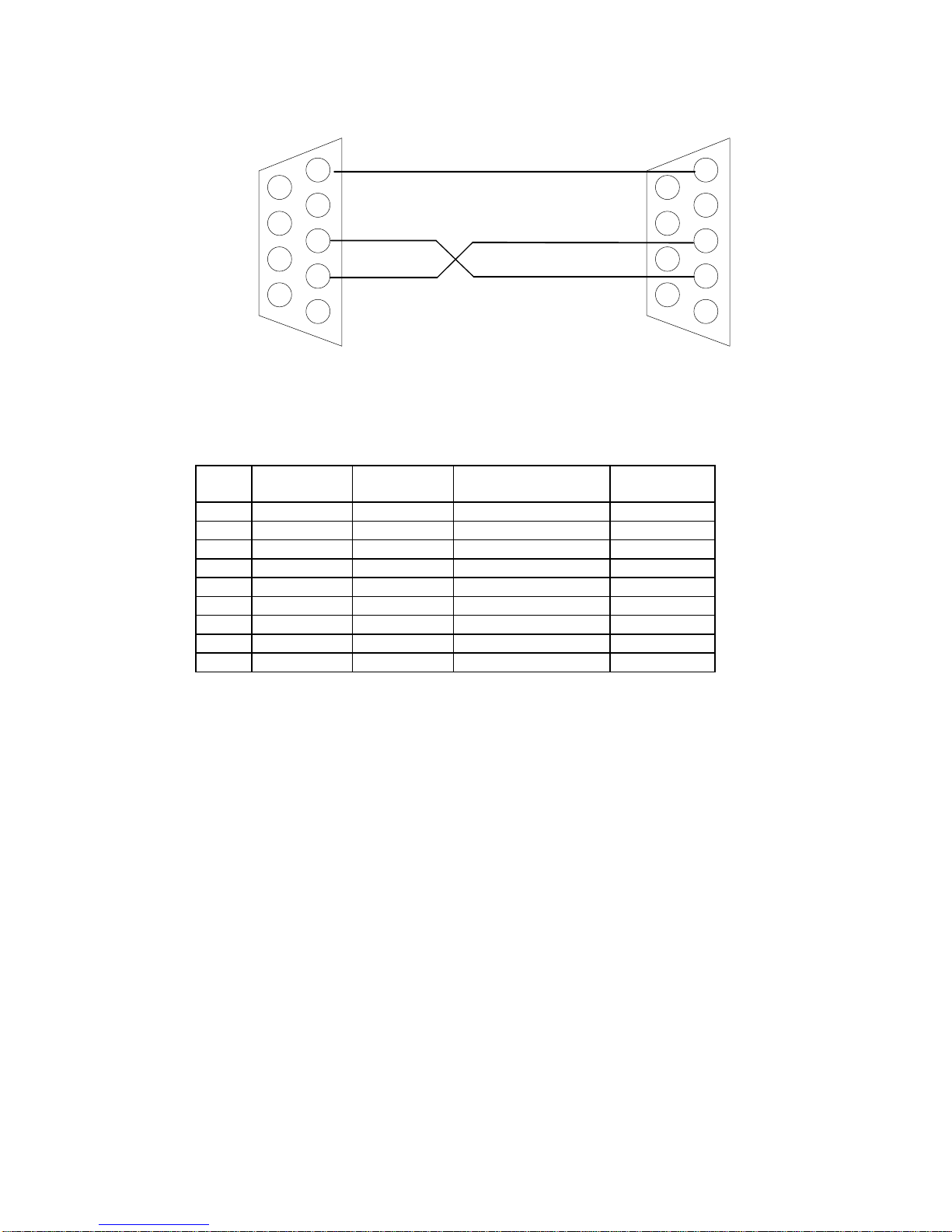
The RS-232 interface is pin compatible with standard PC serial ports, which use RS-574 pin
assignments. To control the system from a PC, a “null Modem” cable is required. A Null Modem
adapter can be used with a “straight through” cable, or a custom cable can be wired, following the
diagram below.
CrossPoint Technologies, Inc 3
Rev H Model MS-400x
5
4
3
2
1
9
8
7
6
5
4
3
2
1
9
8
7
6
9 pin female D connector
9 pin female D connector
Pin
RS-232
Applicability
RS-485
Applicability
Circuit Function
Direction
1 X
TxDataB
Output 2 X
Receive Data
Input 3 X
Transmit Data
Output 4
X
RxDataB
Input 5 X
(Shield)
Gnd 6 X
TxDataA
Output 7
unused
8
unused
9 X
RxDataA
Input
Figure 2 : PC to Matrix Chassis – RS-232
The Serial port connector (CTRL) pin assignments are:
3.2 RS-422 Remote Control Operation
RS-422 operation allows data communication over cables of up to 4,000 feet. Use RS-422 when
the remote computer must be located far from the matrix chassis, or when ambient electronic
noise levels are very high. The RS-422 standard uses balanced differential signaling, for
significantly more reliable communication than RS-232. The drivers and receivers are RS-485
compliant, which makes them suitable for direct interface to full duplex RS-485 systems as well.
The link can operate at four baud rates between 2400 and 19200 bits per second. The other
communication parameters are fixed at 8 bit words, no parity and 1 stop bit. Set your remote
computer interface to the same settings. For long runs, a termination might be required to assure
reliable communication at high baud rates. If you experience data integrity problems (parity errors,
garbled data) try slower baud rates. If slower baud rates help, then try the faster rates with a 120
ohm terminating resistor across the receive data pins (RXA and RXB). Terminate each pair at its
receiver. The terminations can be installed inside the back shells of the cable connectors. The
actual resistance value may be adjusted to match the cable’s characteristic impedance. A value of
120 ohms is typical for twisted shielded pairs.
The serial interface does not support hardware or software flow control. Commands and
responses are relatively short and flow control is not normally required. The command/response
method assures that the host computer can sense if the Matrix is unable to accept more
characters.
CrossPoint Technologies, Inc 4
Rev H Model MS-400x
5
4
3
2
1
9
8
7
6
9 pin female D connector
Computer
RS-485 Connector
TXB
TXA
RXB
RXA
Gnd
TXB
TXA
RXB
RXA
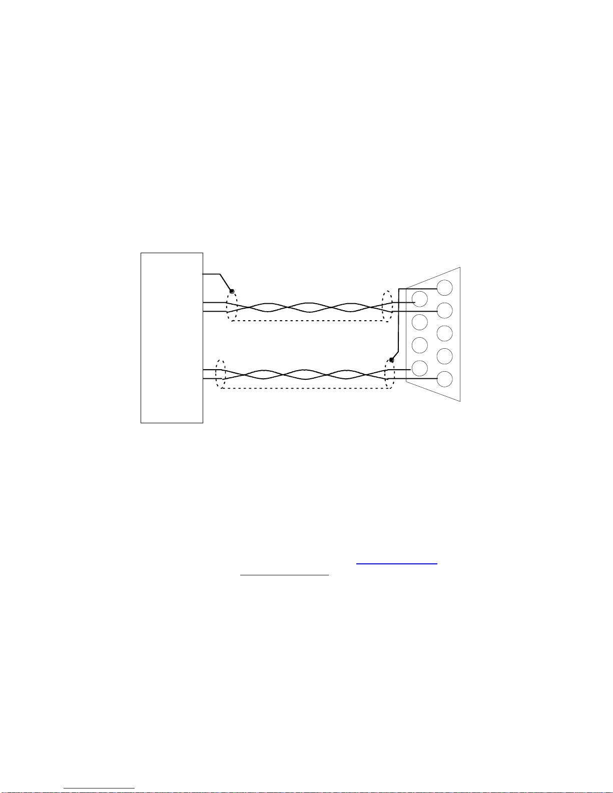
The interface requires 2 twisted pairs of wires between the communicating devices. Shielding is
recommended over the two pairs. For best performance and safety, do not ground the shield at
both ends. Leave one end of the shield unconnected. If each pair is individually shielded, ground
the shield at its source end (driven end) and leave it floating at its receiving end.
The suggested drawing below is for the RS-422 interface using 2 twisted shielded pairs. The
computer side does not show pin numbers, as there are many forms of RS-422 connectors
available. Notice the individual shields are grounded at opposite ends, and there is no ground
continuity between the two devices (the two shields are assumed isolated from each other). In
long runs, this serves to protect both devices from carrying ground currents, especially in the
event of a power line fault in either device. If your cable has individual shields that are in intimate
contact with each other, it may not be possible to avoid ground current flow down the cable shield.
Figure 3 : Computer to Matrix RS-422 Wiring
A standard PC RS-232 port can be transformed to balanced operation using an “RS-232 to RS-
422” or “RS-232 to RS-485” adapter device. These devices are available from a variety of
sources. Some can be powered directly from the RS-232 handshake signals available at the PC
connector. This type is recommended, as it does not require a separate power supply or
transformer for operation.
Suggested sources for these adapters are B&B Electronics (www.bb-elec.com or 815-433-5100)
and Black Box Network Services (www.blackbox.com or 877-877-2269).
CrossPoint Technologies, Inc 5

Rev H Model MS-400x
4 Front Panel Operation
When all connections have been made, power up the Matrix. The matrix will power on in Local
mode, so the front panel is enabled. After displaying the model number, and initializing itself, the
matrix will set itself to the connection paths that existed when it was powered down.
The following sections discuss general operations. Detailed operating sequences appear after the
general discussion
4.1 Remote and Local Modes
Manual operation is permitted whenever the matrix is in Local mode. The front panel can always
be used to view the state of the matrix. But to make changes, the matrix must be placed into
Local mode.
The remote computer can place the matrix in Remote mode, thereby disabling changes from the
front panel. However, the matrix can be returned to Local mode using its front panel menus. The
remote computer can also place the matrix into Local Lockout state. In Local Lockout state, the
front panel is disabled and cannot be used. The remote computer must release the matrix from
Local Lockout state before front panel control can occur. To allow recovery if the remote computer
fails, the matrix can be power cycled. It will always release the Local Lockout and revert to Local
state at power up. The matrix paths will be interrupted during this power cycle operation.
4.2 Setting Switches
To change the matrix connection in a fan in switch, first select the Input that is to be sent to a
different output, by pressing the IN key. To change the matrix connection in a fan out switch, first
select the Output that will have a new input assigned to it, by pressing the OUT key.
Pressing IN/OUT will change the LCD display to an edit mode. A blinking cursor will appear to
indicate the Matrix is waiting for data. Use the numeric keys to specify the desired port, or use the
UP and DOWN keys to increment/decrement through the available port numbers. When the
display shows the desired port, press ENTer to confirm the choice. Pressing ESC will cancel the
edit. At this point, no change has yet occurred to any connections.
Now press OUT for a fan in switch, or press IN for a fan out switch. The appropriate field will
change to edit mode, with the blinking cursor. The text message for this field includes the notation
SEL to indicate that this field is the one that actually makes RF changes. Changes made here are
going to affect the actual paths through the switches. Use the OFF key to break the RF
connection, or enter 0 as the selection. When the display shows the desired port, press ENTer to
confirm the choice. Pressing ESC will cancel the edit. The new RF connections are established at
this time.
As digits are entered, they scroll left, to the maximum number of digits allowed for the matrix. If an
incorrect digit is typed, follow it by correct digits, allowing the erroneous digit to “fall out” of the left
of the display area. Leading zeroes may be entered to flush erroneous digits. The ENT key
accepts only the digits actually displayed. An entry of “0” is the same as pressing the OFF key
When the ENT key is pressed, the Matrix verifies that the number entered by the operator is
within the valid range of the matrix. If the operator enters a number that is out of range for the
matrix (e.g. typing in “9” for a 8x8 matrix), the operation is aborted, and the LCD displays the
previous selection. No change occurs in the RF path. If the number is accepted, the change is
CrossPoint Technologies, Inc 6

Rev H Model MS-400x
made to the RF path, and the display is updated. Any leading zeroes are removed and the cursor
disappears
4.3 Using the Menus
The menu system provides screens for configuring certain internal parameters, such as serial
interface baud rates. It also provides status information regarding internal fault monitoring. There
are screens to restore the matrix to its default settings. Menus are multi-level hierarchies. The
operator chooses a level and moves to the next lower level until the specific items are reached
The normal display is the Connection screen, showing the state of the RF matrix. Press the
MENU key to change to the first menu heading. Use the UP/DOWN keys to scroll through the
headings. Press ENT to move down into the multi-level menus. Press ESC to return to the next
higher menu level.
Once a specific parameter is reached, the parameter can be changed by using the UP/DN keys to
see the various options. When the desired value is displayed, press ENT to make that the current
value of the parameter. Press ESC to abort, and return to the next higher level.
Certain parameters require that the matrix be reset. The reset operation occurs automatically,
without powering off the matrix. The LCD will show “Resetting” followed by the normal initialization
screen. The RF connection will be restored, typically without actually being broken. The reset
operation occurs whenever a communication parameter is changed (RS-232, RS-422 or Ethernet)
4.4 LCD screens and Menus
4.4.1 Menu Tree
Startup Splash
Connection Screen
Remote/Local Mode
BITE Status
Power Supply status
Internal communication status
Maintenance & Setup
Serial Options
RS232/RS422 Interface Selection
Baud Rate
Ethernet
DHCP enable
Static IP address set or DHCP address readback
Port
Static Net Mask
MAC (Hardware) address readback
System Network ID readback
Software Version
Set Defaults
CrossPoint Technologies, Inc 7
Rev H Model MS-400x
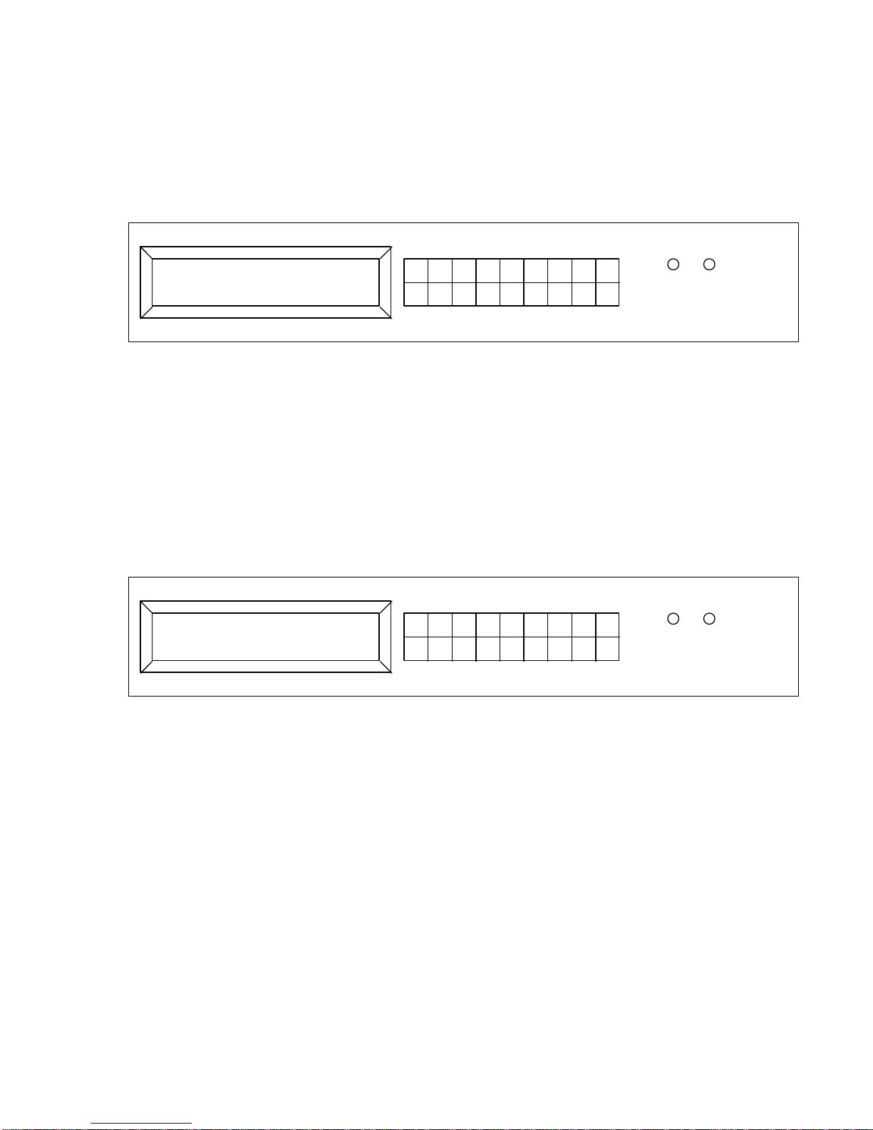
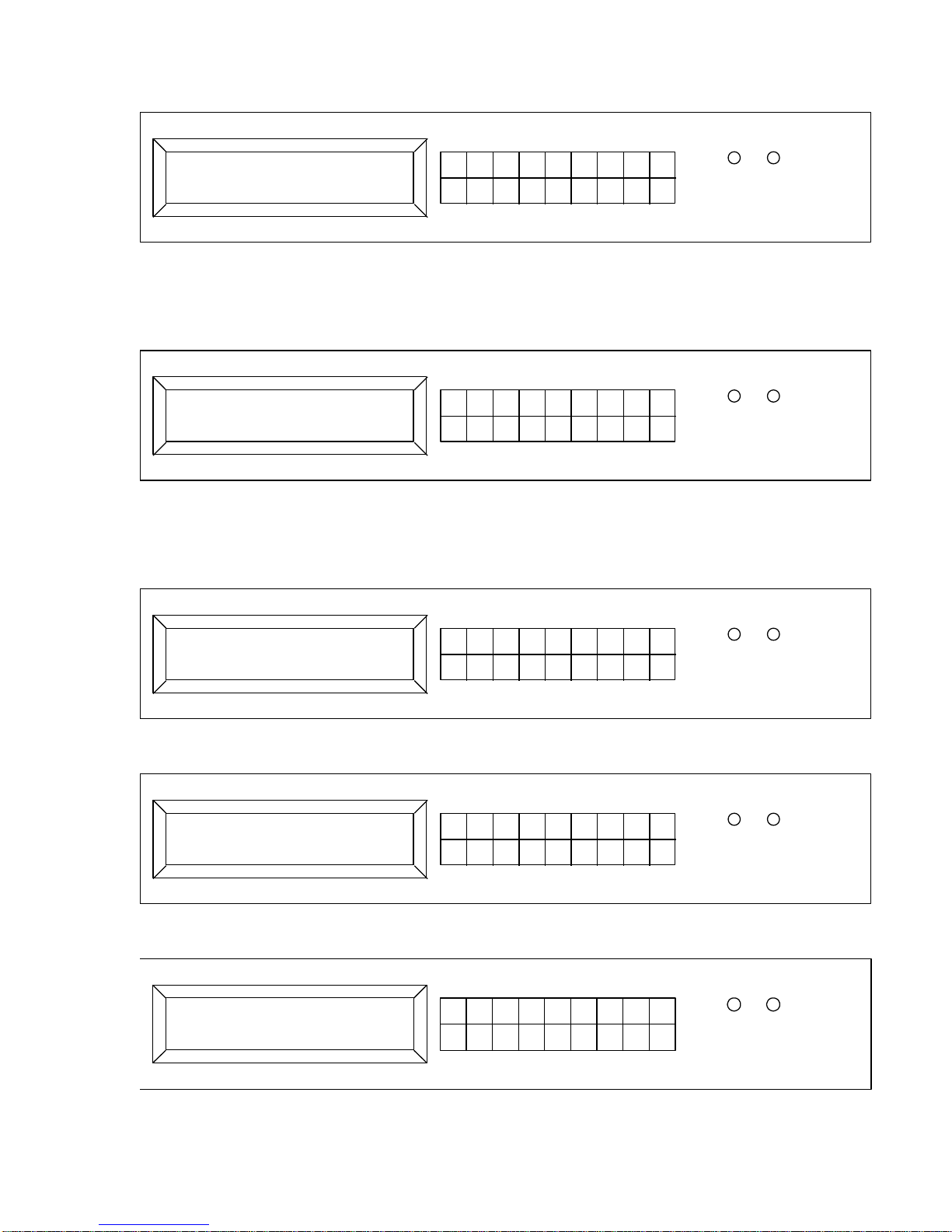
CrossPoint Technologies
MS-4000-32x32-IF-FO
FLT PS
UP IN MENU 1 2 3 4 5 ESC
DN OUT OFF 6 7 8 9 0 ENT
IN : 1 SEL OUT 1
LCL Status : OK
UP IN MENU 1 2 3 4 5 ESC
DN OUT OFF 6 7 8 9 0 ENT
FLT PS
4.4.2 Startup Splash
The splash screen is visible for 3 seconds after power on or reset. If gives the model number of
the controller…
4.4.3 Connection Screen
Screen then goes to the Connection screen. This screen is visible whenever the user has not
entered the Menu system. Connections can be changed from this screen if the Matrix is in Local
(LCL) mode. Connections are restored to the state they were in at power down.
This screen can be accessed by pressing the ESC key several times in any other menus. The
system will back out of menus until it reaches this display.
The sequence of keystrokes to make a connection will differ for Fan In vs. Fan Out switches. Fan
Out switches allow each output to be connected to only a single input at a time, while allowing any
input to be connected to multiple outputs simultaneously. Conversely, a Fan In matrix allows an
input to be connected to a single output at a time, while an output can receive signals from many
inputs simultaneously. The LCD display cannot easily show the multiple connections. Therefore,
Fan Out switches are controlled by first specifying an output, and then selecting an input to route
to that output. Fan In switches operate by first selecting an input and then selecting its single
destination at an output.
The display above is from the 32x32-FO. The Output is noted as “SEL OUT” to reinforce the idea
that the Output is being changed when a new selection is entered.
Begin by pressing the OUT key. The channel number can be entered using the numeric keys or
by the UP/DN keys to scroll. Press ENT when complete. Pressing OFF will turn the RF path off
completely. Entering an Input value of 0 will also turn the output OFF. After ENT is pressed, the
blinking cursor will disappear, indicating that the connection has been made. If a number is
entered that is out of range, the screen will revert to the previous Input, and no change in
connection will occur. Pressing ESC will exit the Edit mode without making any changes.
CrossPoint Technologies, Inc 8
Rev H Model MS-400x
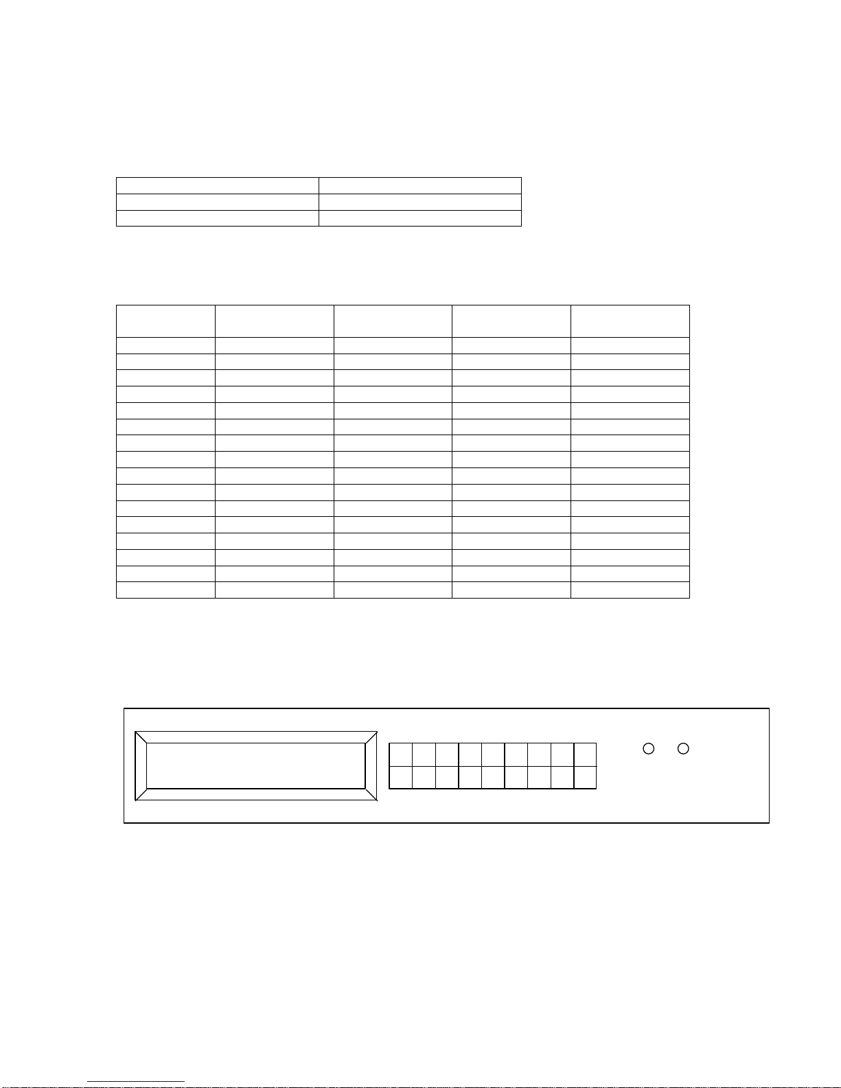
Control : Local
ENT: Edit ESC: Back
UP IN MENU 1 2 3 4 5 ESC
DN OUT OFF 6 7 8 9 0 ENT
FLT PS
Control : Local
ENT: Select ESC: Quit
UP IN MENU 1 2 3 4 5 ESC
DN OUT OFF 6 7 8 9 0 ENT
FLT PS
4.4.4 Remote/Local Control
From the connection screen, pressing MENU will bring up the first Menu heading. Scroll through
the top level items using the UP/DN keys. Press ENT to step into a selection and view the current
setting. Press ENT again to step into the list of choices. Choices are viewed by scrolling UP/DN.
Press ENT to select a new parameter value. Press ESC to back up one level in the menu and
abandon any changes. The first MENU screen will look like this:
The Matrix is in Local mode unless the remote computer has taken over the matrix. If the screen
shows “Remote”, front panel control is disabled. (Matrix settings can be viewed but not changed).
When the system is in Remote mode, control can be acquired by pressing ENT to step into this
menu item. Press UP or DN until the screen shows Local, as in the picture below. The bottom line
instruct the operator to press ENT to confirm this change to Local mode. Pressing ESC will
abandon the change, and back up one level to the top menu list.
The system may also be in Local Lockout mode. In this mode, the remote computer has absolute
control. This menu item cannot be used to regain control from a Local Lockout condition. The
remote computer must place the Matrix into either Remote or Local modes or power must be
cycled to release a Local Lockout.
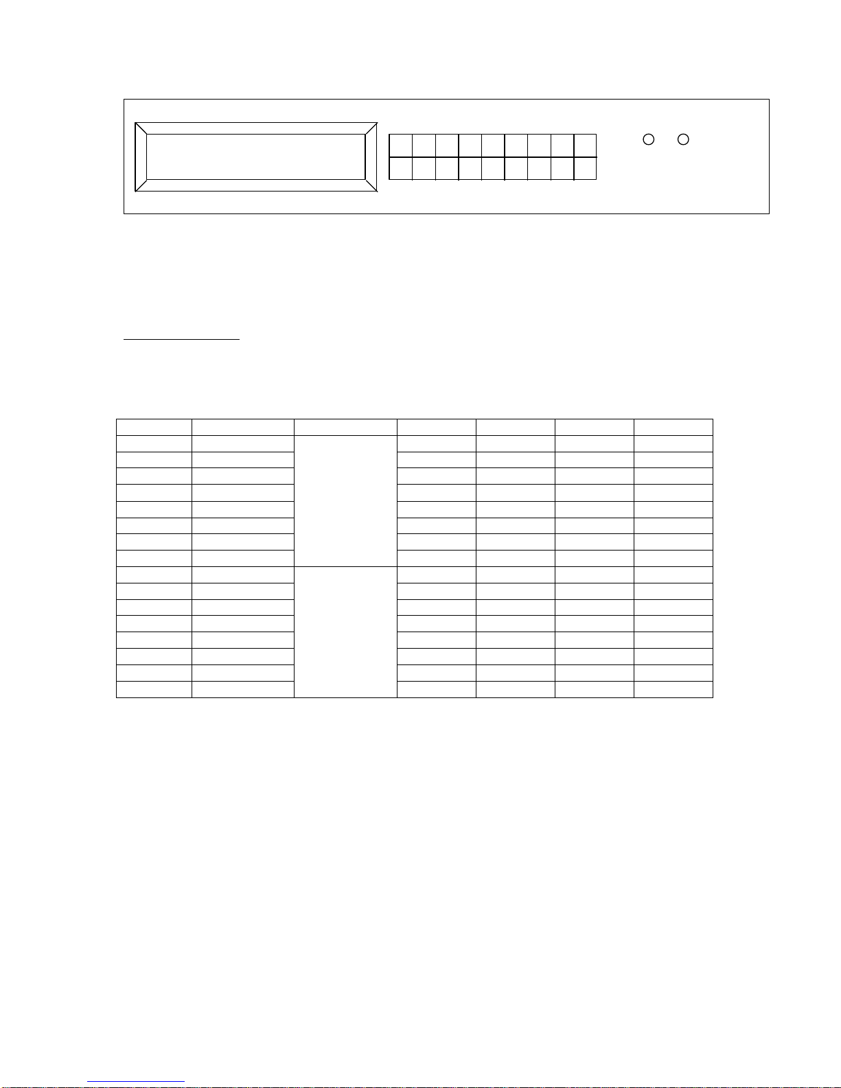
4.4.5 Status
The next top level Menu item, “Status”, displays details from the built in test circuits. This example
shows a Fault reported. The Red FLT lamp will be lit at all times when any fault is detected. If the
problem is a power supply, the PS LED will be lit. Switches with redundant power supplies will
have two LED’s for this purpose. Press ENT to drop down and view details.
While in these menus, the screen is not updated dynamically. Changes to any fault status
information are displayed once for that screen. To see the effect of changes, you must navigate
out of that screen and re-enter to refresh the screen data.
CrossPoint Technologies, Inc 9
Rev H Model MS-400x
Status: Fault
ENT: Details ESC: Quit
UP IN MENU 1 2 3 4 5 ESC
DN OUT OFF 6 7 8 9 0 ENT
FLT PS
12V supply : Pass
ESC: Quit
UP IN MENU 1 2 3 4 5 ESC
DN OUT OFF 6 7 8 9 0 ENT
FLT PS
System Status : Fault
ENT : Select ESC: Back
UP IN MENU 1 2 3 4 5 ESC
DN OUT OFF 6 7 8 9 0 ENT
FLT PS
RS422 COM : Fault
ENT: Details ESC: Back
UP IN MENU 1 2 3 4 5 ESC
DN OUT OFF 6 7 8 9 0 ENT
FLT PS
Com Status F00 B02 C00 A00
ENT: Back ESC: Back
UP IN MENU 1 2 3 4 5 ESC
DN OUT OFF 6 7 8 9 0 ENT
FLT PS
Use the UP/DN buttons to scroll through the various power supply voltages. A sample display is
shown below:
After scrolling through all the power supplies, the screen will show the internal communication
status. This screen is as shown below. The message is “OK” if there are no faults.
Press Enter to see more details. The first screen is the internal RS422/485 communication state.
If a fault is present, there is an option to see details. Press Enter to get the next screen
CrossPoint Technologies, Inc 10

Rev H Model MS-400x
Message
Fault board 1 – PSA 5,12, -5V
Fault board 2 – PSB 5, 2, -5V
F00
OK
OK
F01
Not communicating
OK
F02
OK
Not communicating
F03
Not communicating
Not communicating
Message
Fault board 1 – PSA
5,15V
Fault board 2 – PSB 5,
5V
Fault board 3 – PSA
28V, PSB 28V
F00
OK
OK
OK
F01
Not communicating
OK
OK
F02
OK
Not communicating
OK
F03
Not communicating
Not communicating
OK
F04
OK
OK
Not communicating
F05
Not communicating
OK
Not communicating
F06
OK
Not communicating
Not communicating
F07
Not communicating
Not communicating
Not communicating
Message
Backplane Controller 1
Backplane Controller 2
(MS-4000-32x32 only)
B00
OK
OK
B01
Not communicating
OK
B02
OK
Not communicating
B03
Not communicating
Not communicating
Message
Detector Backplane 1
Detector Backplane 2
(MS-4000-32x32 only)
D00
OK
OK
D01
Not communicating
OK
D02
OK
Not communicating
D03
Not communicating
Not communicating
These two fields show the communication between the master CPU and several other boards.
The “F00” field is the Fault boards (power supply monitors). “F00” is the normal condition with no
communication problems. If a Power supply fault board is not communicating properly, its
appropriate bit is set. Multiple board failures result in multiple bits set in the hex ASCII string.
TheMS-4000-16x16 and 32x32 switches have two of these Fault monitoring boards. Responses
are listed below
The MS-4001 10x6, 12X6, and 16X6 have three of these boards.
Note that this fault does not have anything to do with power supply voltages, per se. However, if
the main CPU cannot communicate with theses boards, their voltage status will be reported with
the last information that the CPU received.
The second item, “B02 is the state of the backplane controller communication. The 32x32
matrices have two backplane controllers. All other matrices have only a single backplane
controller.
The third item, “D00” is the state of the detector backplane communication, if the matrix has signal
detection capability. The 32x32 matrices will have two detector backplanes. All other matrices
have only a single detector backplane controller.
CrossPoint Technologies, Inc 11
Rev H Model MS-400x
Message
Combiner Controller 1
COK
OK
C01
Not communicating
Message
Amp Board 1,
Amps 1-8
Amp Board 2,
Amps 9-16
Amp Board 3,
Amps 17-24
Amp Board 4,
Amps 25-32
AOK
OK
OK
OK
OK
A01
No comm
OK
OK
OK
A02
OK
No comm
OK
OK
A03
No comm
No comm
OK
OK
A04
OK
OK
No comm
OK
A05
No comm
OK
No comm
OK
A06
OK
No comm
No comm
OK
A07
No comm
No comm
No comm
OK
A08
OK
OK
OK
No comm
A09
No comm
OK
OK
No comm
A0A
OK
No comm
OK
No comm
A0B
No comm
No comm
OK
No comm
A0C
OK
OK
No comm
No comm
A0D
No comm
OK
No comm
No comm
A0E
OK
No comm
No comm
No comm
A0F
No comm
No comm
No comm
No comm
Switch Card Status: Fault
ENT: Details ESC: Back
UP IN MENU 1 2 3 4 5 ESC
DN OUT OFF 6 7 8 9 0 ENT
FLT PS
The fourth item, “C01” is the state of the combiner controller communication. The MS-4001-32x32
matrices have one combiner controller installed. A 16x16 matrix or smaller has no combiner
controller. The MS-4000 solid state switch matrix in its standard configuration does not have a
combiner controller.
The fifth item, “A01” is the state of the Amplifier distribution boards. A MS-4001-32x32 has four of
these boards installed when separate amplifier enclosures are provided.
If communication is lost with an Amplifier Distribution board, the amplifier pass/fail state and the
associated power supplies in that chassis will be reported as their last known values.
After RS422 COM, scroll down to see the individual switch card status (or relay driver card status
for MS-4001.)
Press ENTer to see details of the switch cards
CrossPoint Technologies, Inc 12
Rev H Model MS-400x
S0008000000000040
ENT: Back ESC: Back
UP IN MENU 1 2 3 4 5 ESC
DN OUT OFF 6 7 8 9 0 ENT
FLT PS
S (hex)
(binary)
Card cage
Bit 3
Bit 2
Bit 1
Bit 0
0 (MSB)
0000
Bottom
slot 32
31
30
29 0 0000
28
27
26
25 0 0000
24
23
22
21
8
1000
20
19
18
17
0
0000
16
15
14
13 0 0000
12
11
10 9 0
0000
8 7 6 5 0
0000
4 3 2 1 0
0000
Top
slot 32
31
30
29 0 0000
28
27
26
25 0 0000
24
23
22
21 0 0000
20
19
18
17 0 0000
16
15
14
13 0 0000
12
11
10
9
4
0100
8 7 6
5
0 (LSB)
0000
4 3 2
1
This screen shows a long string of hex digits that indicate the communication status of each
switch card in the matrix. The length of the string is 16 digits for the 32x32, and 16 digits for all
other matrices.
Interpretation of the bits in this word is given below for each model
MS-4000-32x32-xx : using example S0008000000000040. The bold text “20” in the bottom card
cage corresponds to the bit 3 being set in the hex digit “8”. This card will carry inputs 17..32 for
output 20. The bold text “7” in the Top card cage corresponds to the bit 2 being set in the hex digit
“4”. This card will carry inputs 1..16 for output 7. These examples indicate that the switch card in
slots 20-bottom and 7-top are not communicating properly.
CrossPoint Technologies, Inc 13

Rev H Model MS-400x
S
Bit 3
Bit 2
Bit 1
Bit 0
0 0 0
0
0
Slot 1
2 3 4
2 5 6 7 8
0 9 10
11
12 0 13
14
15
Slot 16
S
Bit 3
Bit 2
Bit 1
Bit 0
0 0 0
0
0
0
0
Slot 1
2
8 3 4 5 Slot 6
S
Bit 3
Bit 2
Bit 1
Bit 0
0 0 0
0
0
0
0 8 1 0 0
0
MS-4000-16x16-xx: using example S00000200. Notice that not all bits have meaning. The
highlighted slot 7 corresponds to the bit 1 being set in the “2”. This example indicates that the
switch card in slot 7 is not communicating properly.
MS-4001-10x6-xx, MS-4001-12x6-xx: using example S00000008. Notice that not all bits have
meaning. The highlighted slot 3 corresponds to the bit 3 being set in the “8”. This example
indicates that the relay driver card in slot 3 is not communicating properly.
MS-4001-16X6-XB: using example S00000008. Notice that not all bits have meaning. The
highlighted slot 3 corresponds to the bit 3 being set in the “8”. This example indicates that the
relay driver card in slot 3 is not communicating properly.
A display of S00000000 is the normal response with all relay driver cards operating properly.
CrossPoint Technologies, Inc 14

Rev H Model MS-400x
Slot 1
S00000001
Slot 2
S00000002
Slot 3
S00000004
Slot 4
S00000008
Slot 5
S00000010
Slot 6
S00000020
Slot 7
S00000040
Slot 8
S00000080
Slot 9
S00000100
Slot 10
S00000200
Slot 11
S00000400
Slot 12
S00000800
Slot 1
In 1-8 Out 1, also controls Out 1 2X1 Switch
Slot 2
In 9 -16 Out 1
Slot 3
In 1-8 Out 2, also controls Out 2 2X1 Switch
Slot 4
In 9 -16 Out 2
Slot 5
In 1-8 Out 3, also controls Out 3 2X1 Switch
Slot 6
In 9 -16 Out 3
Slot 7
In 1-8 Out 4, also controls Out 4 2X1 Switch
Slot 8
In 9 -16 Out 4
Slot 9
In 1-8 Out 5, also controls Out 5 2X1 Switch
Slot 10
In 9 -16 Out 5
Slot 11
In 1-8 Out 6, also controls Out 6 2X1 Switch
Slot 12
In 9 -16 Out 6
Each Relay driver card failure is reported as follows:
Each group of 4 slots has its failures added together to determine a HEX value to be reported.
Slots 1, 2, 3, and 4 Group 1
Slots 5, 6, 7, and 8 Group 2
Slots 9, 10, 11, and 12 Group 3
As an example, if S00000A13 being reported would show a failure of the Slots 1 and 2 (ex. 3),
Slot 5 (ex. 1), and Slots 10 and 12 (ex. A)
Each Relay driver card function is as follows:
CrossPoint Technologies, Inc 15
Rev H Model MS-400x
Maint & Setup
ENT: Select ESC: Quit
UP IN MENU 1 2 3 4 5 ESC
DN OUT OFF 6 7 8 9 0 ENT
FLT PS
4.4.6 Maintenance & Setup
This top level menu item allows the setup of the serial port, and allows reading the software
version identifier.
Press ENT to drop into the menu and scroll through the choices.
CAUTION
If any of the serial or Ethernet settings are changed, when the
user navigates back to this top level menu item, the switch matrix
will reset itself and begin using the new parameters. Switch
matrix connections will be interrupted while this reset takes
place, and will then be automatically restored. Reset typically
takes less than 10 seconds, depending on network response
times.
CrossPoint Technologies, Inc 16
Rev H Model MS-400x
Serial Options
ENT: Select ESC: Quit
UP IN MENU 1 2 3 4 5 ESC
DN OUT OFF 6 7 8 9 0 ENT
FLT PS
COM Mode: RS232
ENT: Select ESC: Quit
UP IN MENU 1 2 3 4 5 ESC
DN OUT OFF 6 7 8 9 0 ENT
FLT PS
COM Mode: RS422
Press ENT to Confirm
UP IN MENU 1 2 3 4 5 ESC
DN OUT OFF 6 7 8 9 0 ENT
FLT PS
Baud Rate: 19200
ENT: Edit ESC: Back
UP IN MENU 1 2 3 4 5 ESC
DN OUT OFF 6 7 8 9 0 ENT
FLT PS
Serial Options
All serial communication settings are made from these menu items. Press ENT to drop into these
items
The default RS232 mode is shown here.
Pressing ENT will allow scrolling through the other choices. RS422 and (future) Ethernet are
selected from this menu. To select RS422, use UP/DN until the screen shows RS422. Press ENT
to change the interface. Changing Serial mode parameters will cause the Matrix to reset itself
automatically when the action is confirmed, and will be operational again in about 6 seconds.
Similar menu choice selects baud rate. Factory default is 19200 baud.
Press ENT to drop into the menu item and scroll through available choices. Press ENT to change
the baud rate. Changing Serial mode parameters will cause the Matrix to reset itself automatically
when the action is confirmed, and will be operational again in about 6 seconds
CrossPoint Technologies, Inc 17
Rev H Model MS-400x
SW Version: v1.01
ENT: Back ESC: Back
UP IN MENU 1 2 3 4 5 ESC
DN OUT OFF 6 7 8 9 0 ENT
FLT PS
Ethernet Options
ENT: Select ESC: Quit
UP IN MENU 1 2 3 4 5 ESC
DN OUT OFF 6 7 8 9 0 ENT
FLT PS
DHCP: Off
ENT: Edit ESC: Back
UP IN MENU 1 2 3 4 5 ESC
DN OUT OFF 6 7 8 9 0 ENT
FLT PS
4.4.6.1 Software Version
This read only display shows the current installed version of firmware in the system controller.
4.4.6.2 Ethernet Options
All Ethernet communication settings are made from these menu items. Press ENT to drop into
these items
The default condition is for static IP addressing. Therefore, DHCP is off by default. The DHCP
selection menu appears first because its state will have an effect on data items presented in later
menus.
Pressing ENT will enter the DHCP edit mode. Then use the UP/DN keys to set DHCP ON or OFF
as desired. Press ENT to accept the setting and return to this level of the menu. Press ESC to
abort any change and leave the current value in place
The next menu item is the IP address screen. This screen shows either the static IP address
assigned during setup (when DHCP is off) or it shows the address received from the DHCP
initialization process if DHCP is enabled. If DHCP is enabled, but no address has been assigned,
the screen will show an address of 000.000.000.000. In this case, communication with the matrix
is not possible.
CrossPoint Technologies, Inc 18
Rev H Model MS-400x
Addr: 192.168.001.053
ENT: Edit ESC: Back
UP IN MENU 1 2 3 4 5 ESC
DN OUT OFF 6 7 8 9 0 ENT
FLT PS
Port: 23
ENT: Edit ESC: Back
UP IN MENU 1 2 3 4 5 ESC
DN OUT OFF 6 7 8 9 0 ENT
FLT PS
Mask: 255.255.255.000
ENT: Edit ESC: Back
UP IN MENU 1 2 3 4 5 ESC
DN OUT OFF 6 7 8 9 0 ENT
FLT PS
If DHCP is off, press ENT to manually set the IP address. Your network administrator will be able
to help determine this address. The address must be manually typed using the numeric keys.
Leading zeroes must be entered, as each field is a fixed 3 characters. Press ENT when done to
accept the new address and return to the upper level menu. If DHCP is enabled, this screen is
read-only.
The next menu item is the IP Port value. The default is Port 23, the standard port for Telnet
services. If another port is desired, it may be set here. Ports in the full range 1..65535 are
accepted. Leading zeroes are not required for this item.
When using static addressing (DHCP Off), a network mask must be supplied. The next menu
item allows this mask value to be entered. Like the IP address, leading zeroes are required
because the number is broken into 4 fields, and a decimal point key is not available. Set the
netmask according to the addressing system used in your network. Your Network Administrator
will know what this value should be.
If DHCP is On, this field is read only, and shows the last value entered manually, not the value in
use on the network.
For system administration, it is often important to know the hardware MAC (Media Access
Control) address. This address is assigned in silicon at the factory, and is globally unique among
all Ethernet devices. The next menu item displays the MAC address of the matrix switch, and is
read-only.
CrossPoint Technologies, Inc 19
Rev H Model MS-400x
MAC: 12:34:56:78:9A:BC
ENT: Back ESC: Back
UP IN MENU 1 2 3 4 5 ESC
DN OUT OFF 6 7 8 9 0 ENT
FLT PS
Name: CPTI_78:9A:BC
ENT: Back ESC: Back
UP IN MENU 1 2 3 4 5 ESC
DN OUT OFF 6 7 8 9 0 ENT
FLT PS
Set Defaults
Press ENT to Confirm
UP IN MENU 1 2 3 4 5 ESC
DN OUT OFF 6 7 8 9 0 ENT
FLT PS
In some networks the System Administrator will want to put a name for the switch into the IP
routing tables. If DHCP is being used, the IP address can change dynamically, so it becomes
difficult to find the matrix by its IP address. A name can be assigned, so that the matrix can be
found by name-server techniques. To simplify this setup, the switch matrix creates a unique name
for itself and registers this name with the local router during DHCP initialization. The name is
always of the format “CPTI_” followed by the last 6 characters of its MAC address. (The first 6
characters of the MAC will always be the same for all CrossPoint products, so they add no
uniqueness to the name). The CPTI_ header allows the matrix to be easily identified in a router
table by the System Administrator, and matched to a specific switch matrix.
4.4.7 Set Defaults
This menu item erases all communication parameters, and sets the matrix to RS232, 19200
baud. All switches are set to their OFF condition (Failsafe models revert to failsafe condition). The
Matrix resets itself and will be operational again in about 6 seconds.
CrossPoint Technologies, Inc 20

Rev H Model MS-400x
5 Remote Control
5.1 Interfaces
The matrix system may be controlled by serial port or by Ethernet (if installed). For serial control, a
dumb terminal or terminal emulator program, such as HyperTerm (found on most PC’s) provides
a manual interface for simple command entry and status message readback. For Ethernet
control, a Telnet program (or Hyperterm) provides similar capability across the network.
The matrix system does not echo characters as they are typed, so use the Local Echo feature of
your program to see what you type. Every completed command returns either a copy of what was
received, or an error code. This reply returns after the command has executed, signaling that the
command was acted upon.
5.2 Protocol
All messages and responses over the User IO interface are ASCII strings. No binary data is
transmitted over this interface. Commands consist of 2 ASCII characters and may require an
optional parameter string. Commands are terminated by carriage return (hex 0D). Execution does
not begin until the carriage return is received.
Multiple commands may be sent on the same line if separated by a semicolon (“;”). Incoming
command strings are limited to 63 characters, including the carriage return. Outgoing responses
are truncated if they would exceed 255 characters.
In most cases, a command mnemonic can be followed by an ASCII question mark (“?”). This form
of the command will be interpreted as a status request and the current value associated with that
command will be returned. The state of the device will not be altered by a status request.
Parameters are typically separated by commas. Certain commands can have multiple parameter
sets which are separated by parentheses.
The 2 character mnemonics are case insensitive on receipt, but will be upper case in the
response.
Transmit and receive operations are synchronous to one another. Incoming commands and
status requests are executed in the order received. Responses are returned when the command
is complete. All commands are echoed after completion as a verification to the remote computer.
If the host computer does not wait for the response string, it should allow 250 msec between
commands to ensure that it does not overrun internal buffers.
When input numbers or output numbers are required as parameters, they may omit leading
zeroes. Up to 3 characters are accepted. The maximum matrix size is 999 x 999.
When parameters are out of range (e.g. an input number is higher than the number of installed
inputs), those specific portions of the command are ignored. In commands which include lists of
items, all items are processed unless an error is encountered. All items after an error are
discarded, as well as the error itself. An error response is returned.
CrossPoint Technologies, Inc 21

Rev H Model MS-400x
Mnemonic
Description
AO
All Switches Open
AR
Amplifier Status Report (optional hardware required)
CE
Clear Last Error
CS
Internal Communication Status
DS
Report All switch positions
ER
Error Response
FB
Signal Path Connection Report (optional hardware required)
LE
Report Last Fault
ID
Identify Matrix
RD
Restore Defaults
RL
Remote/Local state
SC
Switch Close
SD
Signal Detector Report (optional hardware required)
SO
Switch Open
SZ
Matrix Size
TR
Test Report
Command Set
5.2.1 Summary
NOTE: Refer to Addendum for commands specific to the MS-4001-32x32-HF Switch Matrix
5.2.2 Detailed Command and Status Formats
AO All Switches Open
FORMAT: (1) AO
RESPONSE: (1) AO - if the matrix is not Failsafe type
(2) FS - if the matrix is a Failsafe type.
DESCRIPTION: Opens all switches in the matrix or sets them to their failsafe positions.
AR Amplifier Status Report (optional hardware required)
FORMAT: (1) AR
(2) AR?
RESPONSE: (1) same as format 2
(2) AR001P,002P,003P,004F,005P,…. ,032P
(3) ER003:AR
DESCRIPTION: When separate amplifier chassis are used, the system reports the health of the
amplifiers with this command. Each amplifier is monitored by watching its DC current. If the
current is either too high or too low, the amplifier is reported as failed. The response returns each
channel number and a ‘P’ indicating Pass, or a ‘F’ indicating Fail. Response 3 is returned if the
optional hardware is not installed
CrossPoint Technologies, Inc 22

Rev H Model MS-400x
Message
Fault board 1 – PSA
5,15V
Fault board 2 – PSB 5,
5V
Fault board 3 – PSA
28V, PSB 28V
FOK
OK
OK
OK
F01
Not communicating
OK
OK
F02
OK
Not communicating
OK
F03
Not communicating
Not communicating
OK
F04
OK
OK
Not communicating
F05
Not communicating
OK
Not communicating
F06
OK
Not communicating
Not communicating
F07
Not communicating
Not communicating
Not communicating
CE Clear Last Error After Reporting
FORMAT: (1) CE
RESPONSE: (1) CE0000
DESCRIPTION: Returns hex ASCII value (16 bits as 4 characters.)This is a bit mapped indication
of the most recent fault information. After returning this value, the error bits are reset. CE0000
indicates there were no faults since last CE command. This command is identical to the LE
command, except that LE does not clear the fault information after reporting it. See LE command
for more detail on the meaning of the bits in the response.
CS Communication Status
FORMAT: (1) CS
RESPONSE: (1)CSFOK,BOK,DOK,COK,AOK,S0000000000000000
(2)CSFOK,BOK,S0000000000000000
(3)CSF01,B01,D01,C01,A01, S0000000000000000
(4)CSF01,B01, S0000000000000000
DESCRIPTION: returns communication faults if any. Response 1 and 3 correspond to switches
with signal detectors, combiner controllers and amplifier distribution boards installed. Responses
2 and 4 are returned from switches without signal detectors, combiner controllers or amplifier
distribution boards. FOK indicates all PS fault boards are communicating properly. BOK indicates
all the backplane controller boards are communicating properly. DOK, if present, indicates that
detector backplanes are communicating properly. AOK, if present, indicates that the amplifier
power distribution boards are communicating properly. COK, if present, indicates that the
combiner controller boards are communicating properly.
If there are current faults, they will be returned in two hex digits as shown in response 3 and 4.
The F01 and B01 (and D01, C01, A01 if their respective boards are installed) error messages can
be interpreted according to the tables below. The S00… string shows communication failures to
the switch cards or relay driver cards. These bits can be interpreted according to the tables in the
front panel discussion of these faults. A matrix up to 32x32 returns 16 digits after the ‘S’. A matrix
that is 16x16 or smaller returns 8 digits after the ‘S’.
The MS-4001-32x32-HF Matrices have three of these boards.
Note that this fault does not have anything to do with power supply voltages, per se. However, if
the main CPU cannot communicate with theses boards, their voltage status will be reported with
the last information that the CPU received.
CrossPoint Technologies, Inc 23

Rev H Model MS-400x
Message
Backplane Controller 1
Backplane Controller 2
(MS-4000-32x32 only)
BOK
OK
OK
B01
Not communicating
OK
B02
OK
Not communicating
B03
Not communicating
Not communicating
Message
Detector Backplane 1
Detector Backplane 2
(MS-4000-32x32 only)
DOK
OK
OK
D01
Not communicating
OK
D02
OK
Not communicating
D03
Not communicating
Not communicating
Message
Combiner Controller 1
COK
OK
C01
Not communicating
Message
Amp Board 1,
Amps 1-8
Amp Board 2,
Amps 9-16
Amp Board 3,
Amps 17-24
Amp Board 4,
Amps 25-32
AOK
OK
OK
OK
OK
A01
No comm
OK
OK
OK
A02
OK
No comm
OK
OK
A03
No comm
No comm
OK
OK
A04
OK
OK
No comm
OK
A05
No comm
OK
No comm
OK
A06
OK
No comm
No comm
OK
A07
No comm
No comm
No comm
OK
A08
OK
OK
OK
No comm
A09
No comm
OK
OK
No comm
A0A
OK
No comm
OK
No comm
A0B
No comm
No comm
OK
No comm
A0C
OK
OK
No comm
No comm
A0D
No comm
OK
No comm
No comm
A0E
OK
No comm
No comm
No comm
A0F
No comm
No comm
No comm
No comm
The second item, “B02” is the state of the backplane controller communication. The 32x32
matrices have two backplane controllers. All other matrices have only a single backplane
controller.
The third item, “D01” is the state of the detector backplane communication, if the matrix has signal
detection capability. The 32x32 matrices have two detector backplanes if this feature is installed.
A 16x16 matrix or smaller will have only a single detector backplane controller (if installed).
The fourth item, “C01” is the state of the combiner controller communication. The MS-4001-32x32
matrices have one combiner controller installed. A 16x16 matrix or smaller has no combiner
controller. The MS-4000 solid state switch matrix in its standard configuration does not have a
combiner controller.
The fifth item, “A01” is the state of the Amplifier distribution boards. A MS-4001-32x32 has four of
these boards installed when separate amplifier enclosures are provided.
CrossPoint Technologies, Inc 24
 Loading...