

Page 1
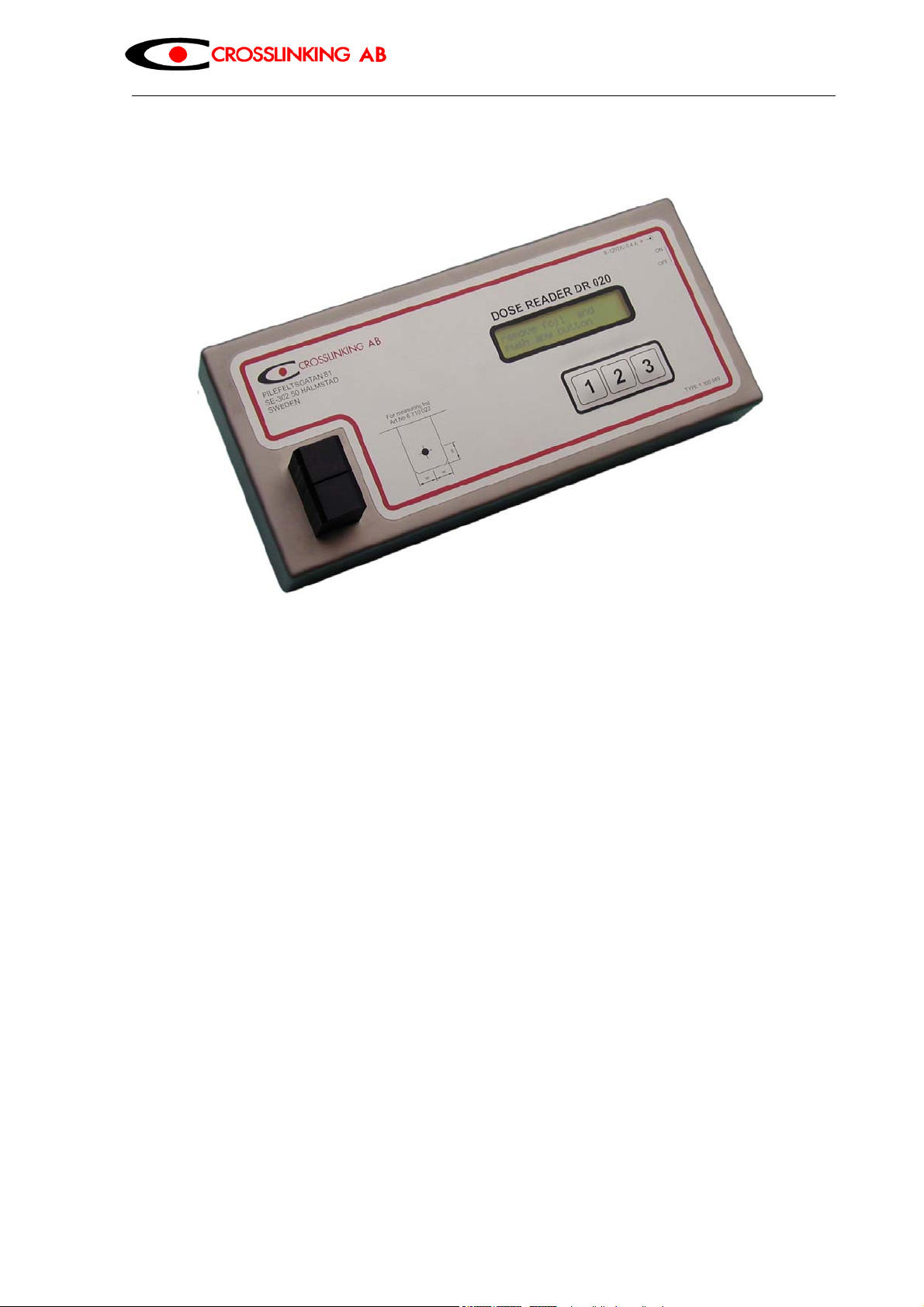
Operating manual for dosimeter type DR020
1. Purpose of the device
2. Design
3. Connection
4. Operation
5. Calibration
6. Application
7. Method of measurement
8. Principle of measurement
9. Measuring film
10. Measured values via the interface
11. Malfunctions / servicing
12. Technical data
___________________________________________________________________
ELECTRON CROSSLINKING AB
Sweden - Head office Telefon/Phone Germany Telefon/Phone
Skyttevägen 42 +46 (0)35 15 71 30 Brühlstraße 7 +49 (0)7473 920 281
SE-302 44 Halmstad Telefax DE-72147 Nehren Telefax
+46 (0)35 14 82 06 +49 (0)7473 920 282
EB_DOS_01_Manual_EN_01.doc
Page 1 of 14
Page 2

Notices
Copyright © 2000 Electron Crosslinking AB
Skyttevägen 42
SE-302 44 Halmstad
Sweden
Tel: +46 35 15 71 30
Fax: +46 35 14 82 06
All Right Reserved
The reproduction, transmission or use of this document is not permitted without express written
authority.
Electron Crosslinking AB shall have no liability for any indirect or speculative damages arising from the
use of this product.
Technical data subject to change.
Other product and corporate names may be trademarks of other companies and are only for
explanation and to the owner's benefit, without intent to infringe.
Page 2 of 14
Page 3

1. Purpose of the device
This dosimeter is used to measure ionizing radiation in processes such as cross-linking of paints or
plastics.
As a measurement instrument, it is extremely simple to use: a measuring film is exposed to radiation
and then evaluated using the dosimeter in a matter of seconds. The measured value is displayed in
kGy. By offsetting optical components, performing measurements using a 10-Bit A/D converter and
averaging values over several measurements, the dosimeter offers a very high degree of accuracy.
Measurement errors only occur if there are irregularities in the measuring film (thickness and color
distribution). Thanks to these features, the dosimeter is a valuable tool in quality assurance.
1.1 Electron beam irradiation
When using electron beam equipments a three-dimensional determination of dose distribution is
a must for reproducible production procedures.
In the case of low-energy electron beam equipment, the short range of the electrons causes
considerable alteration in the absorbed dose with the penetration depth. One useful dosimeter
employs polyvinyl butyral (PVB) with pararosaniline cyanide: this colors on irradiation with
electrons or UV (red discoloration).
This very thin film (approx. 20 µm or 20 g/m
2
) has good resolution in depth doses for
measurements with low-energy electrons. As the film is supplied by the meter, it is also possible
to measure the dose distribution across the effective width at high resolution, as follows:
Radiation is directed onto a strip which corresponds to the beam width and evaluation then
performed at cm intervals, for example.
2. Device design
The dosimeter is accommodated in a sealed high-grade steel housing which effectively shields
it from interference. A keyboard overlay on the function keys and the display protects against
dirt.
To allow a better view while working, you can tilt the device at an angle using the retractable
stands. Just three keys are necessary to activate all of the device functions; all necessary data
is shown on a 2 x 20 character display screen.
The measuring head, which has a measurement slot 0.5 mm in width, contains the transmitter
and receiver optical components.
A processor the size of a check card is located inside the device: this controls all of the
functions and dose calculation.
3. Power supply
The power is supplied by a standard power supply unit. The measurement device is designed
for continuous operation. The device can be switched off with the power switch located on the
device.
The serial interface can be used to read the stored values into a PC for further processing.
Page 3 of 14
Page 4
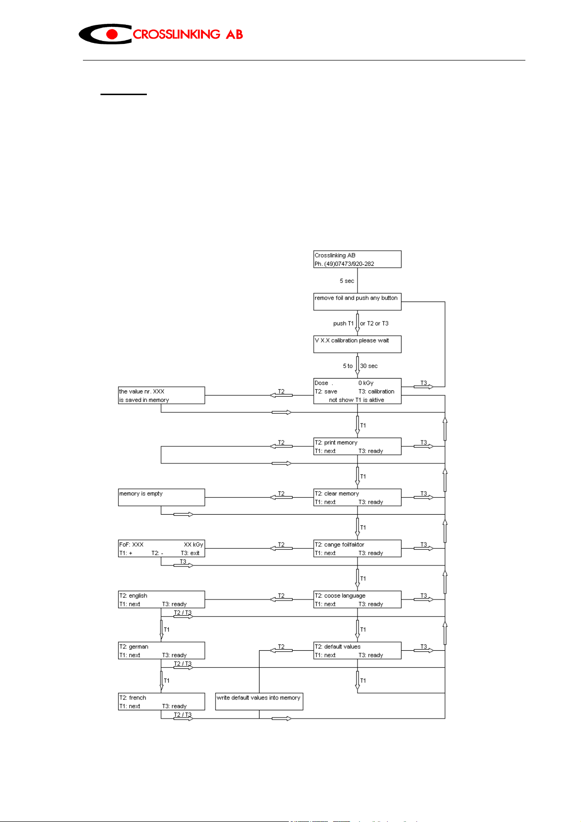
4. Operation
The dosimeter is activated by means of the power switch. The user is then requested to remove
any measuring film still in the measuring head and to press any key. Now calibration of the
device takes place: the red and green intensities are adjusted to a particular value. Because
optical components are subject to drift, you should switch on the device 30 min before use and
then recalibrate it after the half hour. In this way, accurate measurements are achieved.
Once calibration is complete, the device is ready to perform measurements. When a radiated
film (see item 10) is inserted, a dose reading immediately appears on the display. A constant
measured mean value is displayed after 8 to 32 measurements. Constant values are identified
by a colon displayed before the dose reading (after 8 measurements) or an asterisk (after 32
measurements).
Flow chart / menu structure
Page 4 of 14
Page 5
4.1 Menu 1 / main menu
Dose reading, Save, Calibration
4.1.1 T1 Next
The T1 key is used to proceed to the next menu. Even though this function does not appear on
the display, this key is active.
4.1.2 T2: Save
The T2 key is used to save the value that is currently displayed. The count value of the value
(up to 8128 values can be stored) is displayed when the value is stored.
4.1.3 T3: Calibration
The device can be recalibarated after the turn-on time (in accordance with the procedure
described in section 4) and while the device is in operation.
4.2 Menu 2
Print memory
4.2.1 T1 Next
The T1 key is used to proceed to the next menu.
4.2.1 T2: Print memory
See section 10 "Measured values via the interface"
4.2.3 T3: Ready
The T3 key is used to return to menu 1.
4.3 Menu 3
Clear memory
4.3.1 T1 Next
The T1 key is used to proceed to the next menu.
4.3.2 T2: Clear memory
The T2 key is used to erase all data from the memory. Subsequently the message „memory is
empty“ is displayed and you are returned to menu 1.
4.3.3 T3: Ready
The T3 key is used to return to menu 1.
4.4 Menu 4
Change foil factor
4.4.1 T1 Next
The T1 key is used to proceed to the next menu.
4.4.2 T2: Change foil factor
Every new dosimeter film batch may have a different offset. This can be corrected by entering a
film-specific value. The keys T1+ and T2- can be used to select a factor in the range of 0 to 255.
4.4.3 T3: Ready
The T3 key is used to return to menu 1.
Page 5 of 14
Page 6

4.5 Menu 5
Choose language
4.5.1 T1 Next
The T1 key is used to proceed to the next menu.
4.5.2 T2: Choose language
This key calls up the menu that allows you to select a language. The following choices are
available:
- German
- English
- French.
- T1 To make a selection
- T2 To confirm action and return to menu 1
4.5.3 T3: Ready
The T3 key is used to return to menu 1.
4.6 Menu 6
Transmissions
4.6.1 T1 Next
The T1 key is used to proceed to the next menu.
4.6.2 T2: Default values
The T2 key is used to display the LED transmissions:
- Red channel output value: XXX input value: XXX
- Green channel output value: XXX input value: XXX
The intensity of both channels (input values) must be above 500. If this value is not reached, the
device needs to be readjusted.
4.6.3 T3: Ready
The T3 key is used to return to menu 1.
5. Calibration
After starting, the device is calibrated. After prolonged operation, recalibration of the device is
recommended to compensate for any thermal drifts of the optical components, for example,
thereby ensuring accuracy of the dose evaluation.
5.1 Measurements with a dosimeter film WITHOUT supporting film
If this measurement method is used, ensure that there is no dosimeter film in the measuring
head during calibrating.
5.2 Measurements with both dosimeter film AND supporting film together
As the dosimeter film is normally supplied with a supporting film, measurements can also be
performed with supporting films. If this measurement method is used, calibration must be
performed with the supporting film only (i.e. without the dosimeter film).
Page 6 of 14
Page 7
6. Application
The dosimeter has been designed to perform measurements in the field of electron beam
engineering. Nowadays, procedures in electron beam engineering are tested and implemented
at an acceleration voltage of 50 keV up to the MeV range. At low acceleration voltages, it is
important to measure not only the exact dose, but also the depth dose. This is only possible if
the measuring film used is thin enough to enable the resolution in the layer thickness subjected
to irradiation.
6.1 Depth dose measurement
In the case of most depth dose measurements, you simply need to superimpose layers of
measuring film and then perform the evaluation. This results in a 20 g/m
Our thin measuring film (just 20 g/m
2
2
) provides this resolution with a measuring system which is
grid.
easy to use.
For accurate depth dose measurements, we recommend that you layer thin polyester film
sheets (10 µm equal to 10 g/m
This method compensates for variations in the thickness (+/- 2 – 3 µm) of the dosimeter
measuring film and yields improved resolution. A resolution of 10 g/m
correspondingly accurate dose at the end of the stack, via the measuring film of 20 g/m
2
g/m
, dose loss is minimal, thus reducing the incidence of measurement errors.
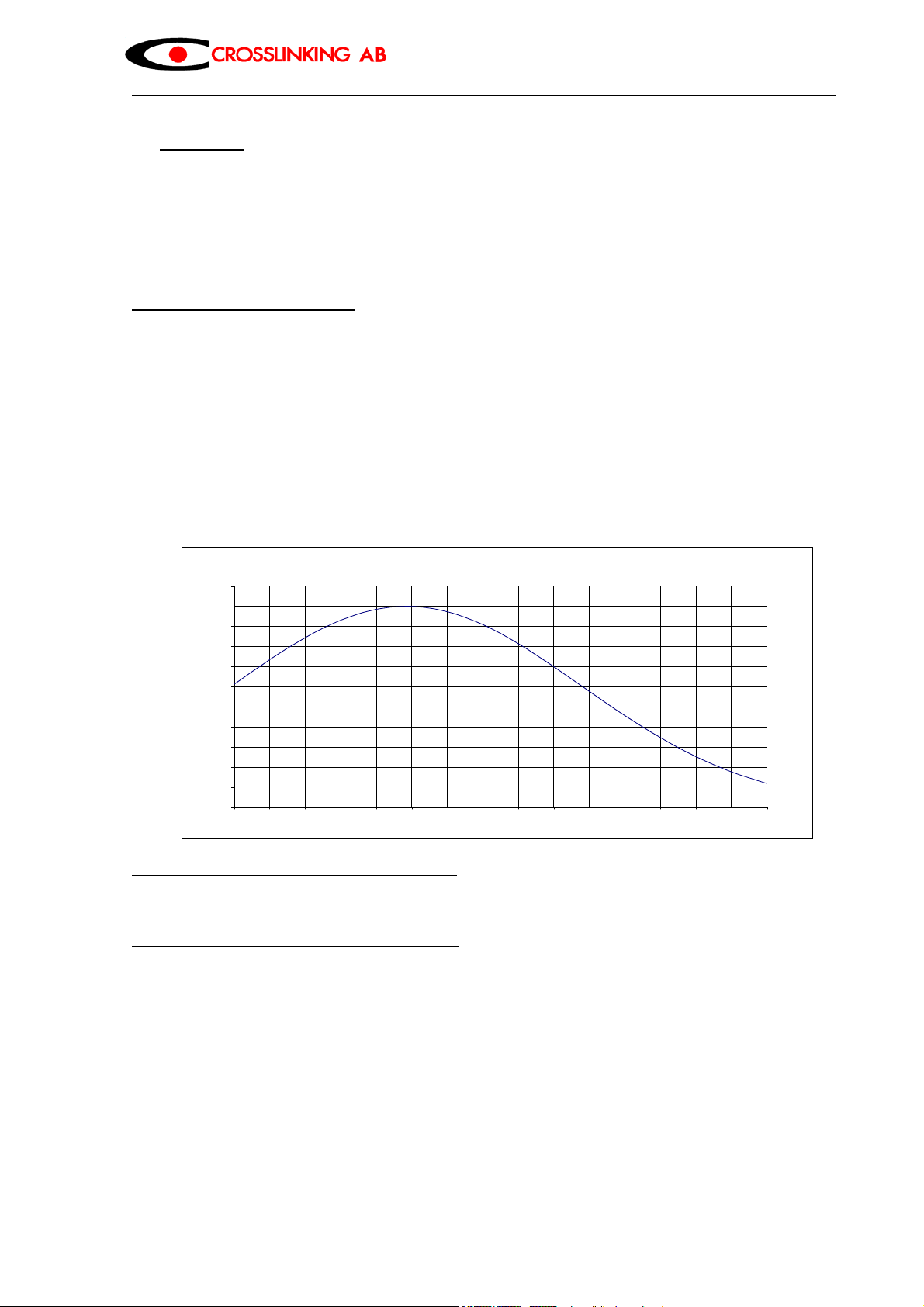
Typical depth dose with a resolution of 20 g/m
110,0
100,0
90,0
80,0
70,0
60,0
50,0
% Ionization
40,0
30,0
20,0
10,0
0,0
0 20 40 60 80 100 120 140 160 180 200 220 240 260 280 300
2
) in individual stacks on the dosimeter film during irradiation.
2
2
:
Dose penetration curve for 150 kV
Mass per un it area g/m2
is achieved with a
2
. At 20
6.2 Measurements across the effective width
The dosing accuracy across the effective width can be evaluated by attaching a measuring strip
across the effective width, e. g. at cm intervals.
6.3 Measurements in the conveying direction
In the case of EBC–units, which switch from roll to roll and use the track speed to control the
beam of electrons (dose control), you can control the dosing accuracy when starting or stopping
the unit simply by attaching a measuring strip in the track direction - e.g. 3 – 5 m measuring film
- (control setting).
Page 7 of 14
Page 8

I
I
r
I
r
7. Method of Measurement
The film holder contains an optical transmitter which has a light emission of max. 635 nm (red)
and 565 nm (green). The brightness of the LEDs in the red and green areas can be controlled
using two digital /analog converters. The optical receiver, located opposite the transmitter,
measures the intensity in both the red and the green areas.
During this measurement process, the film thickness is measured in addition to the discoloration
in the red area of the film caused by the ionizing radiation. As a result, the dose readings
determined via discoloration can be adjusted in accordance with the thickness of the film.
Measurement of the dose and film thickness is performed at the same location, thus increasing
the accuracy of the dose reading. The dosimeter displays the same dose if one film is used or
two superimposed films, with the same dose in the measuring head.
After starting, the device tells the user to remove any film remaining in the holder.
First the dosimeter adjusts both colors to maximum brightness and then determines which of
the colors has the highest intensity. The other color is reset until both of the measured
intensities are roughly equivalent. These intensities are stored in the memory as the values
and
0
.
g0
By comparing the difference between the intensities, scattered light are suppressed.
The measured values are evened out by software components and a mean value calculated
using 8 of the evened values. A measurement period of 3 times 20ms is required for the
evening process (red value, green value and dark value). If the mean value is constant, a colon
is shown before the dose reading. A second mean value is calculated using 32 evened out
measured values. If this mean value is constant, it is output and identified by a preceding
asterisk.
8. Principle of measurement
Light intensity is attenuated exponentially as it passes through an absorbent medium. Red light
is only absorbed in the carbon-black section of the measuring film. The rosalinin which has
been colored red by the dose absorbs only very little of the red light.
The intensity measurement
can also be used to determine the thickness of the film, if the
other quantities are known.
Green light is also attenuated as it penetrates the film, due to the red discoloration.
However, this red discoloration is proportional to the energy dose (or more specifically the ion
dose) to which the film has been exposed.
Page 8 of 14
Page 9
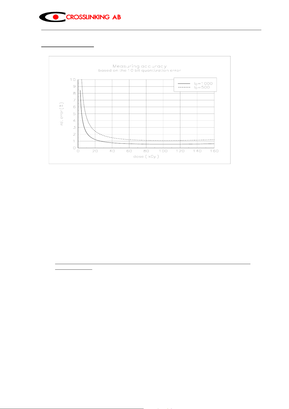
8.1 Quantization error
With a dose of 40 kGy and a measured intensity of 1000, the relative quantization error is 0.75 %.
With the same dose and a measured intensity of 500, the relative quantization error is 1.5 %.
9. Measuring film
Pararosanilin is also UV-sensitive and should therefore not be exposed to sunlight. The film
should be stored away from bright light.
However, the film is not so sensitive that it has to be covered during the measurement process.
No discoloration will occur if the film sheets are openly placed on the measurement surfaces in
ordinary room lighting.
The measuring film is supplied in rolls 20 m long and 25 mm wide; it consists of 2 layers for
ease of handling.
- the actual dosimeter film (thickness approx. 20 µm or 20 g/m
2
) and
- a supporting film (thickness approx. 50µm) for better handling of the dosimeter film.
Please note that the dosimeter film must always lie on top when measuring doses with lowenergy electrons.
The dosimeter film should be evaluated without the supporting film. If you wish to perform
evaluation using supporting film, the dosimeter must first be calibrated with the supporting film
and without the dosimeter film.
The maximum operating temperature must be taken into account during measurement. A
maximum temperature of 50°C is specified for the film. At temperatures higher than this, the
dosimeter film is prone to stronger discoloration than that caused by the ionizing radiation. In
electron beam engineering, irradiation does not produce this temperature.
Delivery size: 20 m long x 25 mm wide rolls Article No: 6 710 022
Dosimeter film thickness: approx. 20 µm
Supporting film thickness: approx. 50 µm
Max. dose in the linear range: 80 kGy
Max. temperature: 50°C
Tempering: 15 min at 40°C, after irradiation,
for artificial ageing at accurate measurements
Storage: in dark places, sensitive to UV
Page 9 of 14
Page 10
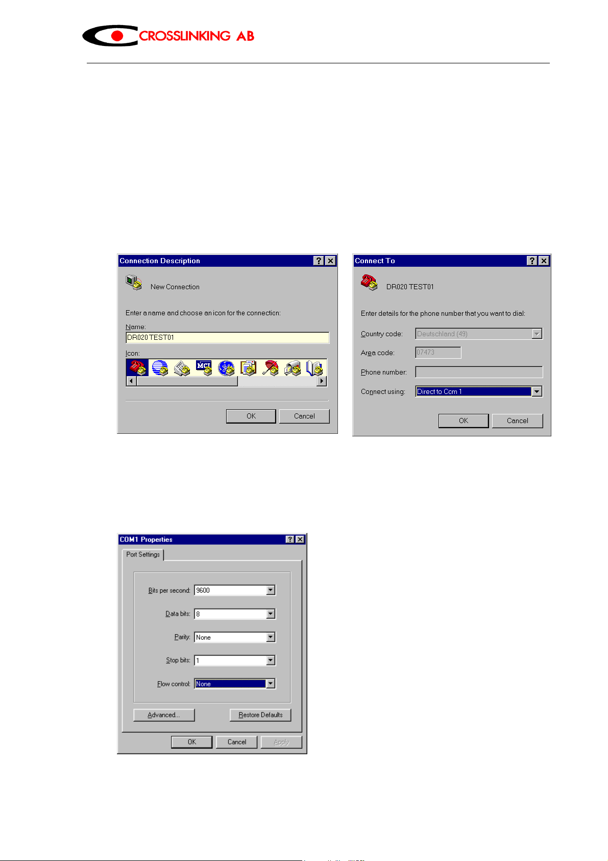
10. Measured values via the interface
The device is equipped with a serial interface located on the rear of the device. This allows the
stored data to be read into a PC using the Print Memory option. The Windows HyperTerminal
program is used for this purpose. A null modem cable is used to connect the measurement
device via the serial interface to the PC (normally using COM 1 or COM 2).
Carry out the following steps to print the data:
- Start the Windows program HyperTerminal.
- From the File menu, select New Connection and confirm your selection.
- Enter the name of the file into the New Connection window, e.g. MeasuredValues01 and
confirm the name.
- In the File name window (e.g. MeasuredValues01), select Connect Using, choose Direct to
COM 1 or COM 2 (or your interface) and confirm your actions.
- In the Port settings window, select Restore defaults and confirm your selection. These are:
- Bits per second 9600
- Data bits 8
- Parity None
- Stop bits 1
- Protocol None
Page 10 of 14
Page 11
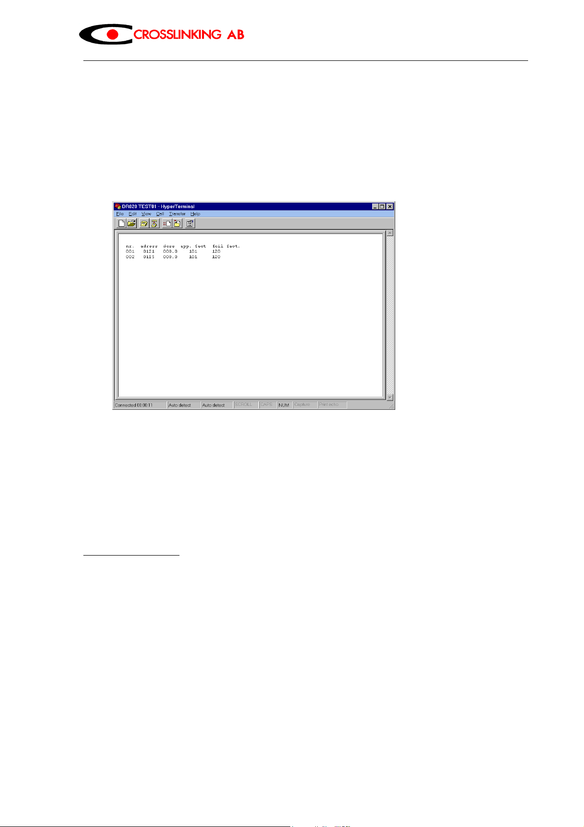
- On the dosimeter DR020, press the "T2: Print Memory" function.
The information is printed in the following format:
No. address dose App.factor Foil factor
001 5D64 048.1 100 100
002 5D68 050.5 100 100
003 5D6C 051.7 100 100
004 5D70 052.7 100 100
005 5D74 055.2 100 100
- Select Save as from the File menu and place the file into the appropriate directory. This file
can imported into a spreadsheet program, for example, for further processing.
11. Servicing / malfunctions
The device has three different modes for error detection and servicing.
- Service mode 1 automatic activation
- Service mode 2 manual activation
- Service mode 3 automatic activation
11.1 Service mode 1
If the device can no longer calibrate "Error T2: service program" is displayed. This function can
be forced by placing a piece of paper into the measuring head during calibration.
In this mode,
- red on (> 500)
- off (0)
- green on (> 500)
can be controlled separately. Check each displayed value which represents the intensity. This
value must be above 500 for red and green with an empty measuring head. A value below 500
indicates that the device must be readjusted or is defective. These intensity values can also be
displayed in the main menu (see section 4.6.2).
Page 11 of 14
Page 12
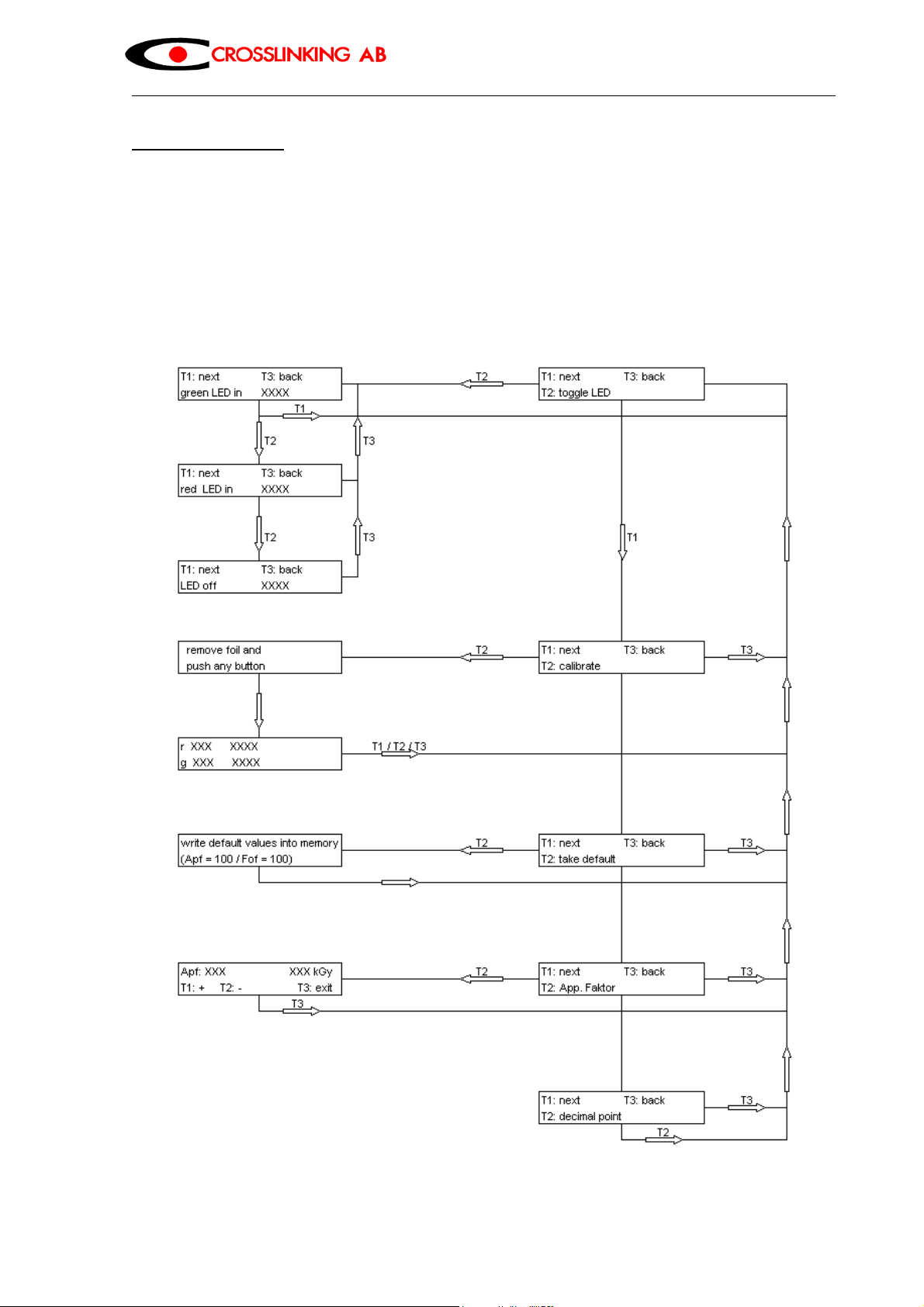
11.2 Service mode 2
If the keys T1 and T2 are pressed at the same time during start-up, the device is switched to
service mode 2. This mode displays important data to simplify diagnostics.
The instrument-specific calibration factor (App.fact) which compensates for the hardware of
different devices can also be set in this mode. Do not change the instrument-specific calibration
factor! Adaptations regarding different dosimeter film batches can be made by modifying the
film-specific calibration factor (foil fact).
Flow chart / menu structure
Page 12 of 14
Page 13

11.2.1 Menu 1 Toggle LED
The T2 key is used to set each LED separately to max. brightness and to display the
transmissions:
- Red channel output value: max. input value: measured intensity
- Green channel output value: max input value: measured intensity
- Both channels off
11.2.2 T2 Calibrate
The T2 key is used to perform the calibration as in the main menu except with additional
information being displayed.
- Red channel output value: 250 input value: measured intensity
- Green channel output value: 250 input value: measured intensity
11.2.3 T2 Take default
The T2 key is used to write the default settings into the memory:
- Instrument-specific calibration factor (app. fact) 100
- Foil-specific calibration factor (foil fact.) 100
- Language English
- Dose reading with one decimal place
- Memory start position
11.2.4 T2 App. fact (instrument-specific calibration factor)
T2 calls-up the menu which can be used to set the instrument-specific calibration factor. Any
factor between 0 – 255 can be set. This allows differences in components to be compensated
for thereby ensuring identical dose readings for different devices. This factor is retained when
exiting with T3 and is not to be modified.
The device must be calibrated (see section 11.2.2) before the instrument-specific calibration
factor is set.
11.2.5 T2 Decimal point
T2 can be used to determine whether the dose reading in the main menu is to be displayed with
a decimal point or not.
The current setting can only be viewed in the main menu. The film or instrument-specific
calibration factor settings are always displayed with one decimal point.
11.2.6 Service mode 3 (battery of SRAM is empty)
If the battery is empty, the defined variables (film or instrument-specific calibration factor) are
lost after the device is switched off.
This is indicated by the message „no valid values in device“
Page 13 of 14
Page 14

12. Technical data
Dimensions: Housing: L x W x H 295 x 135 x 55 mm
Height with measuring head: 90 mm
Measuring head: L x B x H 40 x 25 x 35 mm
Device stands, retractable for tilting at an angle of approx. 23°
Weight: 1.90 kg
Power supply: Voltage 8 – 12 V DC via power supply socket, center contact +, housing -
Current 370 mA
Keyboard: 3 mechanical keys covered with a keyboard overlay
Display: Dot matrix display, 20 characters 2 lines
Optical transmitter: Transmitter diode wavelength red 635 nm, green 565 nm
Optical receiver: Receiver diode wavelength 500 - 700 nm
Interface: Serial interface, Data output via 0 modem cable
Electronics: Check card sized processor with A/D converter
10 bit resolution
battery-backed SRAM, battery life approx. 5 years
Page 14 of 14
 Loading...