

Page 1
VR
VR
Amplifier
Installation Manual
Models: BMF602, BMF1252, BMF2002, BMF754
Page 2

For your records, Crossfire recommends keeping the model and serial
number of your new Crossfire ampifier. This could possibly help you recover
your ampifier in the event of a theft. Use the following spaces to do so and
make sure to keep you manual in a safe place.
Model:
Serial Number
:
Date of Purchase:
Place of Purchase:
Thank you once again for choosing Crossfire! Enjoy!
Page 3

Thank you and congratulations for choosing Cr
Car Audio for your amplification needs. Cr
amplifiers have been significantly improved throughout
the years to assure quality and reliability. Our goal is to
incorporate the latest technology into every Cr
product providing you with incredible power and
unparalleled sound quality. Low distortion and high
efficiency are the result of our precision engineered
circuitry. We are confident that your new Cr
amplifier will provide you with a sound value you will
enjoy for years to come.
1
Page 4

F
Class AB Operation
Fully 2 Ohm Stereo Stable Operation
Military Spec Audiophile Grade Components
y Multi-Stranded Power Torroid
MOSFET Input and Output Transistors
Oversized Capacitor Banks
Wire Free PC Board Layout
Discrete Mount Power and Speaker Terminals
Variable Highpass and Lowpass Electronic Crossover
RCA Preamp Output
-Variable HP/LP/Full crossover
Anti Clip System
Internally Bridgeable
5 W ay Protection Circuitry
Circuitry
Two Year Limited W arranty
eatures
Specifications
MODEL: BMF602 BMF1252 BMF2002 BMF754
RMS Power/4 ohms
Bridge Power, Max 240w x 1 500w x 1 800w x 1 300 x 2
Efficiency, 4 ohms Stereo 68% 68% 69% 63%
THD 0.02% 0.02% 0.02% 0.02%
Bandwidth + 3dB
Signal to Noise >100dB >100dB >100dB >97dB
Damping Factor
Channel Separation >72dB >72dB >72dB >70dB
Input Sensitivity
Input Impedance 20Kohm 20Kohm 20Kohm 20Kohm
Power Fuse 25amp (2) 25amp (2) 30amp (2) 30amp
Dimensions W x H x L
CROSSOVER
Variable Lowpass 50Hz - 6KHz 50Hz - 6KHz 50Hz - 6KHz 50Hz - 6KHz
Variable Highpass
X-Over Slope
Preamp Output Crossover 50Hz - 6KHz 50Hz - 6KHz 50Hz - 6KHz N/A
2
60w x 2 125w x 2 200w x 2 75w x 4
5Hz - 38KHz 5Hz- 38KHz 5Hz- 38KHz 5Hz- 38KHz
>500 >500 >400 >250
310mV to 6V 310mV to 6V 310mV to 6V 310mV to 6V
9 .3" x 2.1" x 10.6" 9 .3" x 2.1" x 15" 9 .3" x 2.1" x 16.8" 9.3" x 2.1" x 16.2"
50Hz - 6KHz 50Hz - 6KHz 50Hz - 6KHz 50Hz - 6KHz
18dB 18dB 18dB 18dB
20% higher.
Page 5
IMPORT
(A
+ B) x (C + D)
(A
x B)(C x D)
ANT
Please read all instructions before installation !
The quality of installation may affect the performance and reliability of your
Crossfire product. If you have any doubts or questions regarding installation, you
may wish to contact your authorized Crossfire dealer. Remember to follow all wire
and fuse requirements suggested in this manual. Warranty may void if proper
installation technique is not used (refer to warranty section in the rear of this
manual).
Operation
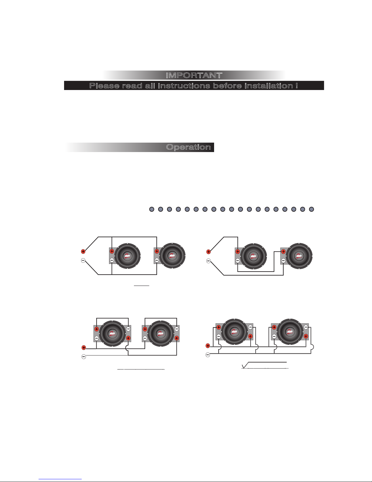
The BMF MOSFET amplifiers will reach their potential output into either a 2 ohm
stereo load or a 4 ohm bridged load. A lower impedance can send the amplifier
into current protection and possibly damage the circuitry. To prevent damage, use
the following formulas to help you calculate the load you are placing on the
amplifier. If you have any difficulties, please contact your local Crossfire dealer of
Crossfire's Technical Assistance at 562-906-0800.
Impedance Equations
Parallel Wiring
R
Series/Parallel Wiring Dual Voice Coil
R
A
Equatio
A
Equation
B
A x B
n
B
(A + B) x (C + D)
A + B + C + D
= R
A + B
C D
= R
R
A B
R
A
Equatio
Parallel Wiring, Dual Voice Coil
Equatio
n
Series Wiring
B
A + B = R
n
C
(A x B)(C x D)
(A + B) + (C + D
D
=R
)
3
Page 6
Mounting
X30 X5 X
X30 X5 X
1
W IN LINE OUT
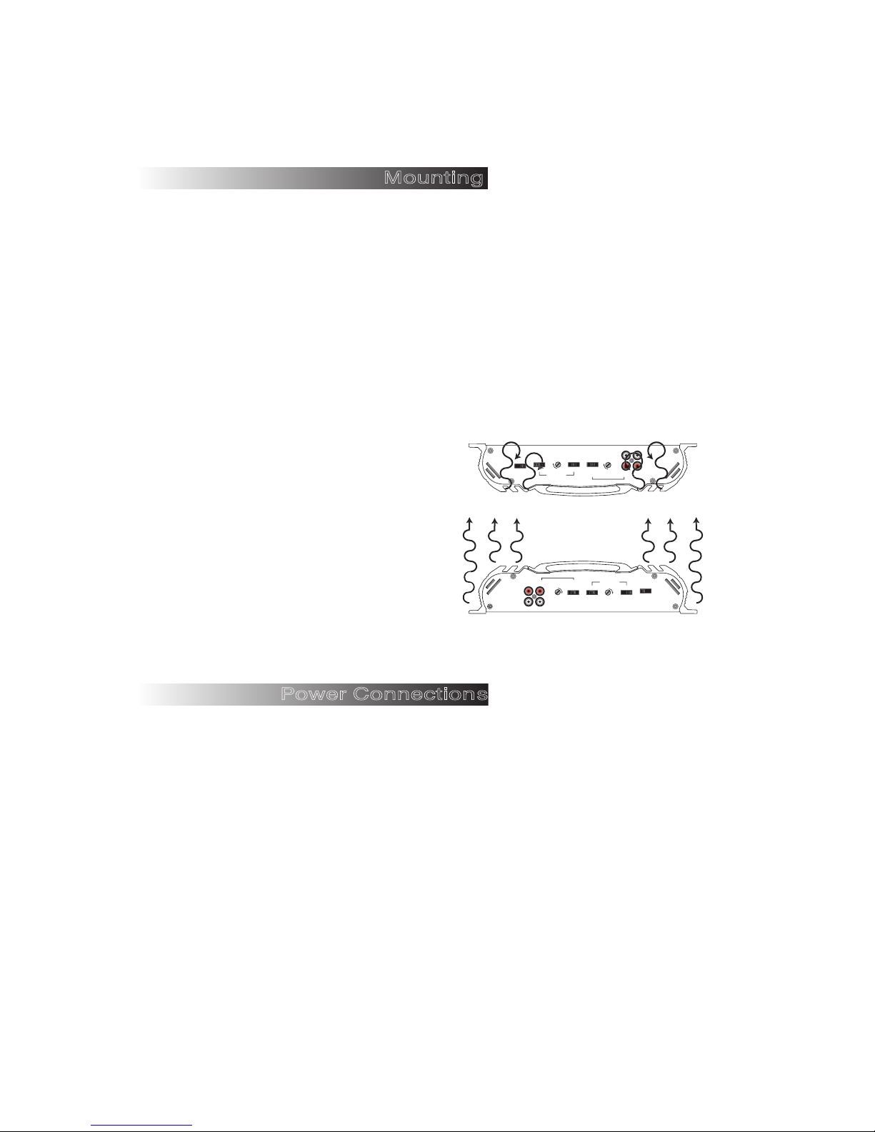
Appropriate mounting is very important for prolonged life expectancy of any amplifier.
Select a location of applicable space that allows for sufficient airflow and provides
protection from moisture. Keep in mind that an amplifier should never be mounted upside
down. Upside down mounting will compromise heat dissipation through the heatsinks and
will engage the thermal protection circuit much sooner. Excessive heat can shorten your
amplifier's life. To maximize heat dissipation, be sure to leave at least 2.5 inches of
clearance around the amplifier. Fans should be used in correspondence with an escape
duct for the heat when mounting the amplifier in an enclosed or restricted area.
Avoid slipping and scratching your new Crossfire BMF amplifier by pre-drilling the mounting
holes with either an 1/8" or 3mm diameter drill bit when using the screws supplied in the
accessory kit. Always investigate the mounting area thoroughly for electrical wires, vacuum
lines, and brake or fuel lines before you start to prevent any potentially expensive mistakes.
Incorrect Mounting
x
Heat is trapped inside the amplifier, shortening
the life of the electronic components.
Correct Mounting
O
Heat is lifted from the amplifier heatsink.
ower Connections
P
N
LOW IN LINE OUT
R
L
(HZ)
1K 6K (X30)
200 1200 (X5)
50 250 (X1)
X30 X5 X1
OFF O
ACS
LEVEL
CROSSOVER
CROSSOVER
HPF FULL LPF
HPF FULL LPF
HPF FULL LPF
CROSSOVER
CROSSOVER
HPF FULL LPF
50 250 (X1)
200 1200 (X5)
1K 6K (X30)
(HZ
L
R
LEVEL
LOW IN LINE OUT
ACS
OFF O
N
X30 X5 X1
)
All Crossfire amplifiers are designed to work within 10.5 to 16 volts DC. Therefore,
as a precaution the vehicle's electrical system should be checked for correct
voltage supply with the help of a voltmeter. First, connect the test leads of the
voltmeter to the battery terminals with the ignition of the vehicle in the off position.
The voltmeter should read no less than 12 volts. Next check the voltage of the
battery with the engine running between 1500 and 2000 rpms. The voltmeter
should now read between 13.5 and 14.5 volts. If your vehicle's electrical is not up
to these specifications, we recommend having it checked by an automotive
mechanic before you further the installation.
4
Page 7

POWER WIRE & FUSE
The proper wire size is very important for an amplifier capable of these power
levels. The following are the recommended fuse values and wire gauge for lengths
up to 20ft.
Model Wire Fuse
BMF602 10awg. 25amp
BMF1252 8awg. 50amp
BMF2002 4awg 60amp
BMF754 4awg 60amp
POWER
Power wire needs be connected directly to the battery using the wire requirements
listed above. Never use the fuse box or any other wire as a source for the power
for an amplifier. Before you start, choose the easiest path to run the wire from the
battery to the amplifier. Generally, try to keep the power wire on the driver's side of
the vehicle (See Signal Inputs & Outputs for explanation). Use the following rules
for running the power cable through the vehicle:
1. Use grommets when passing the power wire through any metal wall of the
vehicle.
2. Avoid sharp corners or sharp body parts that may easily cut through the
insulation on the wire.
3. Avoid running the power wire over engine components and near heater cores.
4. Avoid the gas, brake and clutch pedals and their mechanisms.
5. Use an inline fuse to eliminate the risk of a fire caused by a short in your power
wire.
6. Connect the fuse holder as close to the battery positive as possible.
Once the wire has been run, connect the wire to the battery terminal. As a
precaution, leave the fuse out until all other wire connections are made.
GROUND
The wire used for ground should be of the same gauge as the power wire. Make
sure that you choose a different color (generally black) so that you don't reverse the
polarity at the amplifier terminals. Follow the rules below for connecting the ground
wire properly:
1. Avoid using seat bolts, seatbelt bolts, and fender wells for ground.
2. Choose a metal area close to the amplifier that appears to be a good of ground,
such as the floor.
3. Investigate the area you wish to use for electrical wires, vacuum lines, and brake
or fuel lines.
5
Page 8

Please note that if you are installing multiple high power amplifiers into the vehicle,
you must upgrade the ground strap from the battery to the frame and the frame to
the body of the vehicle. Use the following directions to help aid with the ground
connections.
1. Find a nut and bolt to fit the ring terminal you have chosen.
2. Drill a hole just large enough for the bolt to fit through at the source of ground.
3. Use either a wire brush or sandpaper to eliminate unwanted paint around the hole
you have drilled as to supply a better contact for your ground.
4. Terminate the ground wire to the ring terminal and attach it to the bare metal
using the nut and bolt. It is very important for this connection to be solid.
5. Spread silicon over the screw and bare metal to prevent rust and moisture from
entering the vehicle.
REMOTE TURN-ON
In between the power and ground of the amplifier is a remote turn-on terminal. This
terminal must be connected to a switched +12 volt source to make the amplifier
operational. Typically, remote turn-on leads are provided at the head unit that will
turn on and off the amplifier in correspondence with the source. This means you will
most likely have to remove the head unit from the dash to find the source +12V
output wire.
Once the head unit is pulled from the dash, locate the remote turn on wire. The
majority of vehicles will be using an after market head unit when using an amplifier.
These after market head units generally use a blue or a blue with white wire as the
remote turn on for the amplifiers. However, when using a factory radio, the power
antenna wire should be used as a turn on lead if applicable (colors will vary from
make/model). Only if a lead is not available at the source, a switched +12 volt
supply, such as a toggle switch, should be applied.
Use a minimum of 18-gauge wire, preferably blue, to connect the amplifier to the
head unit. If possible, route this wire along side of the power wire using the same
precautions. Connect the remote output of the head unit to the wire using a barrel
connector or a mating terminal as required by the source unit. You can solder these
wires together, but be sure to use heat-shrink over the connection. Do not place the
radio back into the dash yet.
Speaker Outputs
WIRING
Always choose speaker wire carefully. Make sure that the wire is appropriate for
the speaker you are applying it to. It is highly recommended not to use anything
smaller than 16awg. Consult your dealer.
6
Page 9
As with the power wires, use caution around sharp corners or body parts that may
easily cut through the insulation on the wire. If running wire into the doors, it is
important to use a protective boot in the door jam to protect the wire from being
pinched as well as keeping dust and moisture from entering the vehicle. Use the
factory boots when possible. And always make sure that the wire is out of the way
of the window mechanism.
To connect the wire to the speaker, strip off approximately ½" (12mm) of the
insulation and terminate the wires using insulated speaker terminals (not supplied)
or by soldering the connection to the loudspeaker. Be sure that the polarity at the
loudspeaker is correct.
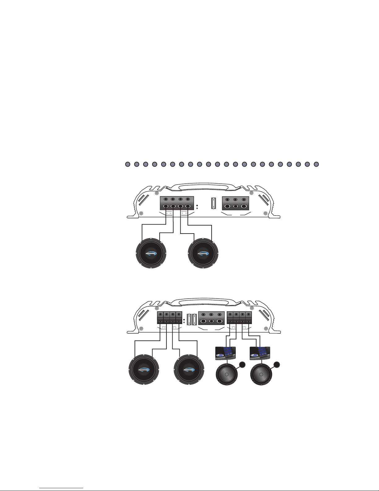
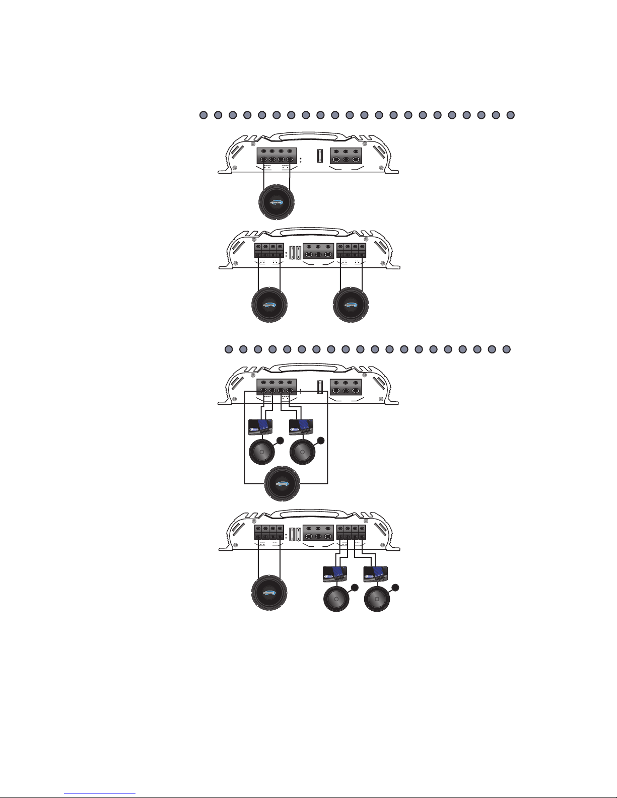
MODELS
BMF602
BMF1252
BMF2002
MODEL
BMF754
-
-
+
+
+
L
R
-
BRIDGED
SPEAKER
POWER
+12 REM
GND
PWR
PR
T
FUSE
-
-
+
+
+
L
R
-
BRIDGED
REAR
SPEAKER
POWER
+12 REM
GND
PWR
PRT
-
-
+
+
+
L
R
-
BRIDGED
FRONT
SPEAKER
FUSE
FUSE
B M F
+
_
B M F
+
_
B M F
+
_
B M F
+
_
+
_
+
_
Stereo Operation
7
Page 10
MODELS
BMF602
BMF1252
BMF2002
MODEL
BMF754
-
-
+
+
+
L
R
-
BRIDGED
SPEAKER
POWER
+12 REM
GND
PWR
PRT
FUSE
-
-
+
+
+
L
R
-
BRIDGED
REAR
SPEAKER
POWER
+12 REM
GND
PWR
PR
T
-
-
+
+
+
L
R
-
BRIDGED
FRONT
SPEAKER
FUSE
FUSE
B M F
B M F
+
_
B M F
+
_
+
_
-
-
+
+
+
L
R
-
BRIDGED
SPEAKER
POWER
+12 REM
GND
PWR
PR
T
FUSE
-
-
+
+
+
L
R
-
BRIDGED
REAR
SPEAKER
POWER
+12 REM
GN
D
PWR
PR
T
-
-
+
+
+
L
R
-
BRIDGED
FRONT
SPEAKER
FUSE
FUSE
B M F
B M F
+
_
+
_
+
_
+
_
+
_
MODELS
BMF602
BMF1252
BMF2002
MODEL
BMF754
Bridged Operation
Stereo/Mono Operation
8
Page 11

Connecting the W
ires
At this point, the power, ground and remote wires should be run to the general
location of where the amplifier is to be mounted. If the wires are to be hidden under
the carpet, you now need to cut a slit for them to come through. To do this, place
the amplifier in the location it is to be mounted to verify where the cuts need to be
made. Make sure that there will be not be a conflict with the mounting of the
amplifier and the wires. Pull the wires through the slit to the terminals leaving
approximately 6" (150mm) of slack and cut the wires to an equal length. Strip off
approximately ½" (12mm) of insulation from each wire. Insert the wires directly into
the terminal and tighten the set screw using a 3mm allen key. Make sure you have
the polarity correct on both the power wires and the speaker wires. Check your
connections by giving the wires a slight tug.
Signal Inputs
Getting a clear signal from the head unit to the amplifier is very important. To
achieve this, the proper signal cables must be used. Estimate the length of the
cables necessary. Take note that the cables will probably not be the exact length
necessary for your vehicle. If you are between sizes, purchase the longer cable.
You can always hide the extra wire.
Be aware of the differences in cable. Better RCA's usually have multiple layers of
shielding and/or twisted pair wiring for better noise rejection. Consult your local
dealer for their recommendations.
LINE LEVEL INPUTS
Car environments are notorious for poorly insulated wires. This means that hiss,
engine noise, and fan noise can easily be picked up through RCA cables if ran
incorrectly. To avoid picking up noise, run the RCA's away from large wire looms
and electric fans if possible. Always make sure to position your patch cables away
from the power wire, preferably on the opposite side of the vehicle. As with the
power wire, use caution around sharp corners of body parts that may easily cut
through the cables.
Located on the opposite side of the power terminals are two sets of line level (RCA)
receptacles. Marked "LOW IN", these receptacles accept signal from the outputs of
the source unit via RCA patch cables. When connecting the signal cables, be sure
the balance (left and right) stays consistent between the amplifier and head unit.
The cables should be marked for easy installation: red is right and black or white is
left.
Once you have finished connecting the signal cables to the source unit, slide the
head unit back into the dash location. Make sure that the head unit is in securely.
9
Page 12
Preamp F
)
eatures
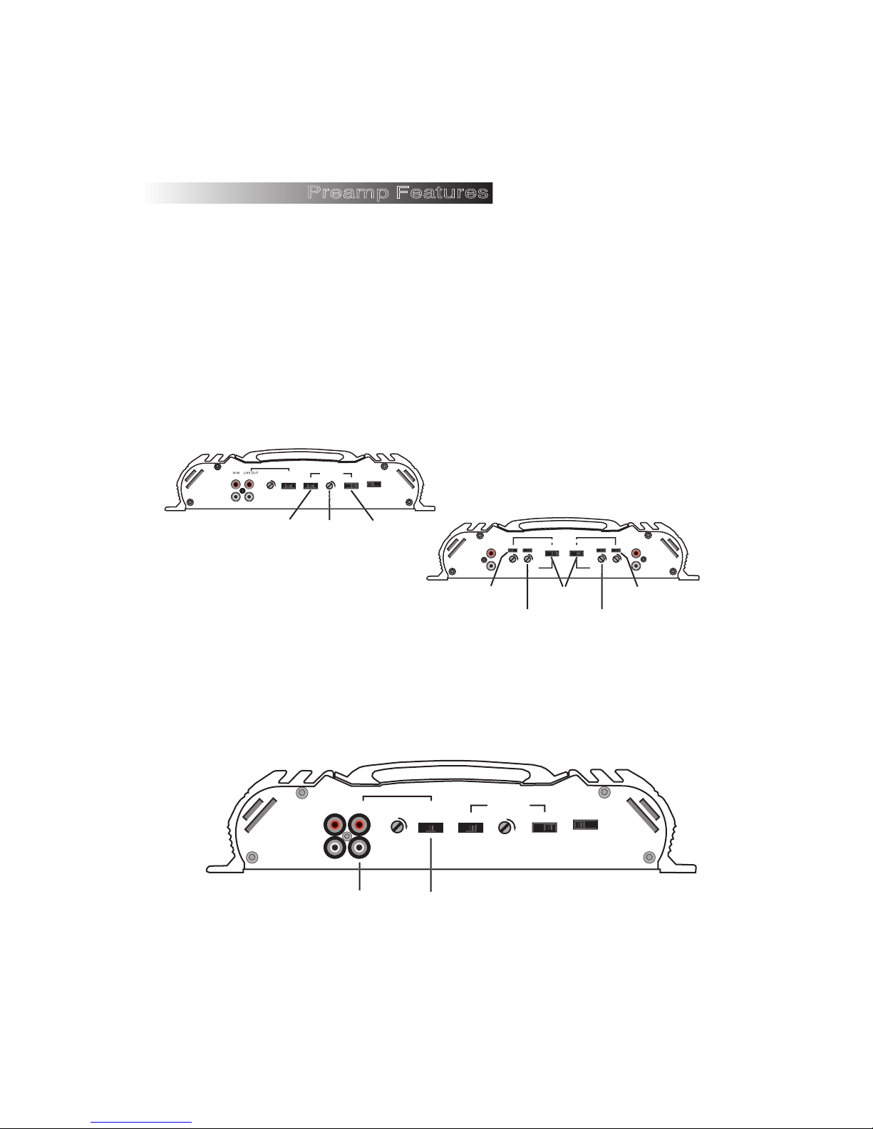
The Crossfire BMF MOSFET amplifiers have a powerful preamp section located on
the panel opposite the power terminals. Included in this preamp section is a fully
adjustable Two Way Crossover for the amplifier, Preamp Output, and the ACS
circuit. These features can be used to improve your system quality as well as make
the amplifiers easier to use on a day to day basis. Please read the following
instructions carefully.
CROSSOVER
On the preamp side of the amplifier there are two selectable crossovers. The
crossover section indicated in the drawing below is allocated to the amplifier itself.
This includes the (highpass filter) HPF/FULL/LPF (lowpass filter), the crossover
frequency selector, and the frequency multiplier. This crossover is flexible enough
so that it can be used for just about any speaker application.
LEVEL
MODELS
BMF602
BMF1252
BMF2002
LO
R
L
CROSSOVER
HPF FULL LPF
Crossover
selector
CROSSOVER
HPF FULL LPF
50 250 (X1)
200 1200 (X5)
1K 6K (X30)
(HZ)
Frequency
selector
X30 X5 X1
Frequency
ACS
OFF ON
Multiplier
LOW IN
R
FRONT
L
Crossover
selector
ACS
OFF ON
HPF FULL LPF
50 250 (X1)
LEVEL
200 1200 (X5)
1K 6K (X30)
)
(HZ
Frequency
selector
CROSSOVER
CROSSOVER
X30 X5 X1
X30 X5 X1
Frequency
Multipliers
ACS
OFF ON
HPF FULL LPF
50 250 (X1)
LEVEL
200 1200 (X5)
1K 6K (X30)
)
(HZ
Frequency
selector
LOW IN
R
L
Crossover
selector
MODEL
BMF754
REAR
On the two channel amplifiers only is another crossover section with a selector
switch marked HPF/FULL/LPF. This crossover section is designated to the preamp
output. The crossover frequency is selected by the crossover allocated for the
amplifier itself, however can be used in Highpass, Lowpass, or Fullrange
independently of that crossover. This allows for multiple system configurations to
be made.
MODELS
BMF602
BMF1252
BMF2002
LOW IN LINE OUT
R
L
LEVEL
CROSSOVER
HPF FULL LPF
HPF FULL LPF
CROSSOVER
50 250 (X1)
200 1200 (X5)
1K 6K (X30)
(HZ)
X30 X5 X1
ACS
OFF ON
10
Preamp
output
Crossover
selector
Page 13
Page 14
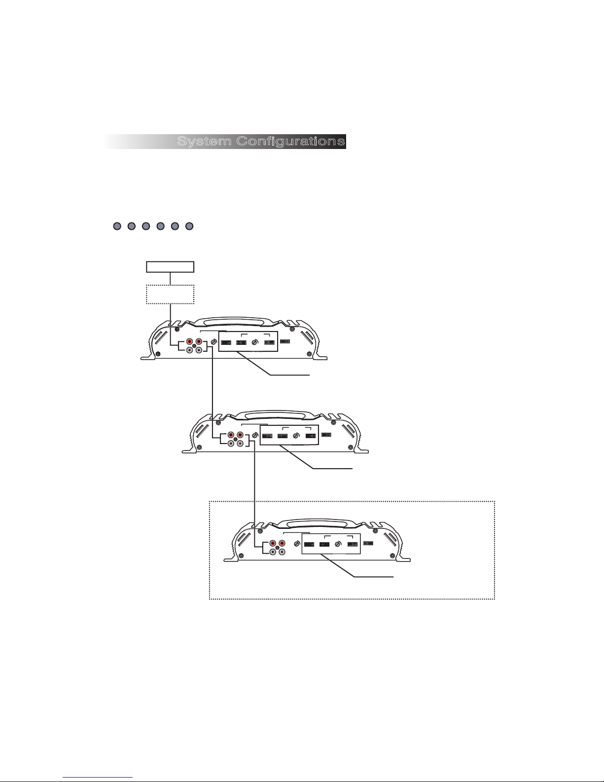
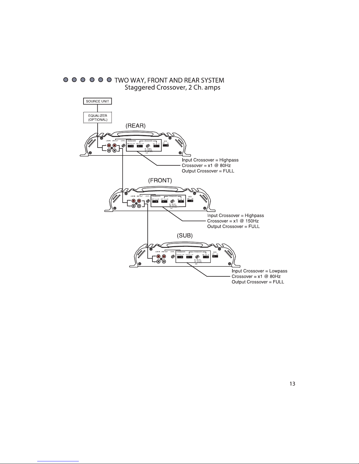
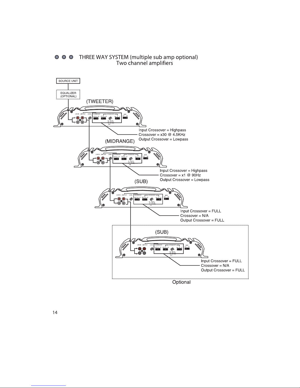
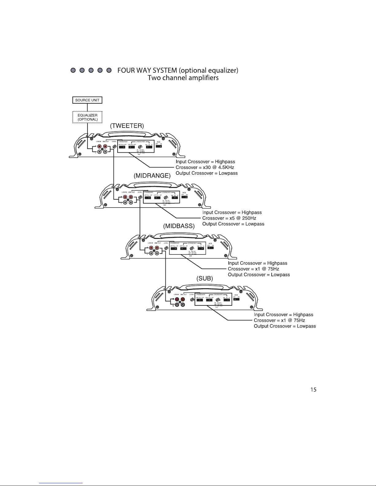
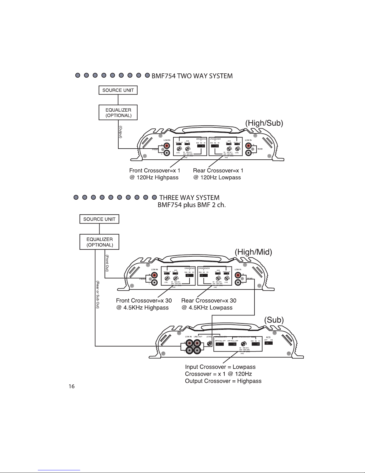
System Configurations
Use the diagrams on the following pages for system configuration. These diagrams
are only samples and your system may vary greatly. Crossover points should be
chosen per the speaker application. For further help, please contact your local
Crossfire dealer or Crossfire's Technical assistance at 562-906-0800.
TWO WAY SYSTEM (optional rear amp)
2 Ch. amps
SOURCE UNIT
EQUALIZER
(OPTIONAL
)
LOW IN LINE OUT
R
L
LEVEL
(SUB)
CROSSOVER
HPF FULL LPF
LOW IN LINE OUT
R
L
HPF FULL LPF
CROSSOVER
X30 X5 X1
50 250 (X1)
200 1200 (X5)
1K 6K (X30)
(HZ)
(FRONT)
LEVEL
CROSSOVER
HPF FULL LPF
LOW IN LINE OUT
R
L
OFF ON
HPF FULL LPF
ACS
Input Crossover = Low pass
Crossover = x1 @ 90Hz
Output Crossover = Highpass
CROSSOVER
50 250 (X1)
200 1200 (X5)
1K 6K (X30)
(HZ)
X30 X5 X1
ACS
OFF ON
Input Crossover = FULL
Crossover = N/A
Output Crossover = FULL
(REAR)
LEVEL
CROSSOVER
CROSSOVER
HPF FULL LPF
HPF FULL LPF
X30 X5 X1
50 250 (X1)
200 1200 (X5)
1K 6K (X30)
(HZ)
ACS
OFF ON
Input Crossover = FULL
Crossover = N/A
Output Crossover = FULL
12
Optional
Page 15
Page 16
Page 17
Page 18
Page 19
 Loading...