

Page 1

Cross Country Wireless, 7 Thirlmere Grove, BOLTON, BL4 0QB, UK
Email [email protected]
Web page http://www.crosscountrywireless.net
Telephone +44 (0) 1204 410626
Mobile +44 (0) 7752 391908
HF Active Vee Antenna
Operating Manual
version 1.0
Partners: Mr C.J.Moulding, Mrs S.M.Moulding
Page 2

Contents
1 Introduction
2 Theory of operation
3 Package contents
4 Assembly
5 LEDs
6 Ethernet cable
7 Suggestions for installation
Page 3

1 Introduction
Thank you for buying a Cross Country Wireless HF Vee Active Antenna.
It was originally designed as part of a contract to replace existing passive
antennas for a professional HF signals monitoring organisation.
It is a wideband active antenna with excellent performance designed and built
with high quality materials to last for years.
2 Theory of operation
The Active Vee Antenna uses a short balanced upright vee dipole to sense the
electric component of the electromagnetic field. The pattern and polarity of the
antenna is nearly omnidirectional with sensitivity to vertically polarised signals as
well as horizontally polarised signals. Muonted close to ground at around 5m agl
the antenna is ideal or NVIS use on 3 to 10 MHz.
The short elements used in the Active Vee Antenna have a very high impedance
with a capacitance of 12 pF over a wide bandwidth.
In the head unit a balanced amplifier using high linearity low noise transistors is
used with a matching balun to match the high impedance of the antenna
elements . Diode limiters and high voltage ceramic capacitors provide protection
from local high RF fields and static electricity from falling rain and snow.
The balanced amplifier feeds an isolation transformer matched to the 100 ohm
balanced load of the ethernet cable connecting the head and base units.
At the base unit another isolation transformer is used to match the 100 ohm
balanced load of the ethernet cable.
Any RF signal or noise induced in the ethernet cable as a common mode signal
is rejected by both transformers.
A diode limiter provide protection from excess RF voltages to receivers
connected to the BNC connector.
DC power is fed from the base unit to the head unit via a current sensing circuit
indicating the remote connection of the head unit with the illumination of a red
LED. Balanced filter networks at each end isolate common mode RF signals and
noise from the head unit amplifier.
Page 4
The amplifier gain has been equalised so that with the standard 20m ethernet
cable supplied with the antenna the overall gain with 12 pF capacitance antenna
elements is flat +/- 1 dB between 3 and 30 MHz.
The frequency response at the lower end is limited to 50 kHz by the transformers
and coupling capacitors.
The amplifier is flat within -6dB up to 150 MHz but the elements change their
electrical characteristics at higher frequencies so the working upper limit is
around 108 MHz.
3 Package contents
2 Whip elements
2 Whip tips
1 Allen key
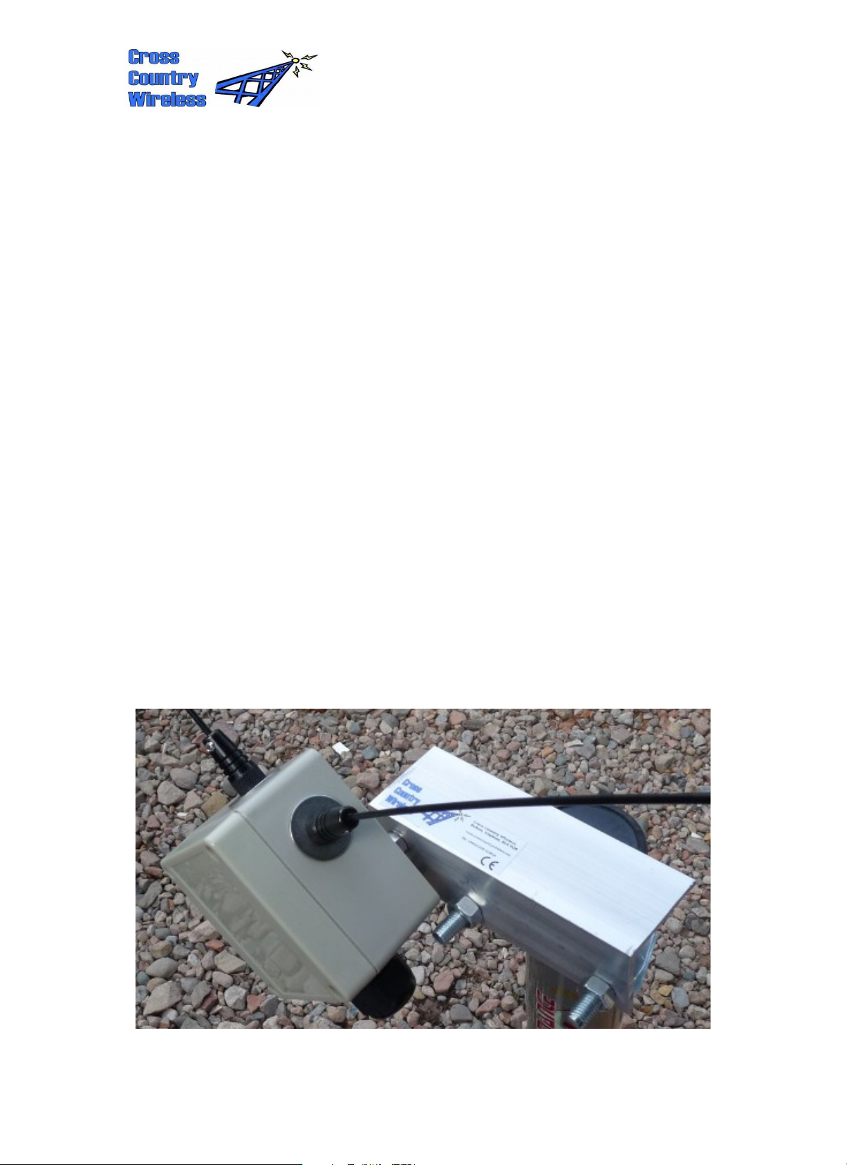
1 Active Vee Antenna head unit with bracket and 50mm U bolt
1 Active Antenna base unit
1 2.5mm DC power connector
20m Ethernet cable with two nitrile rubber sleeves
Page 5
4 Assembly
Head unit
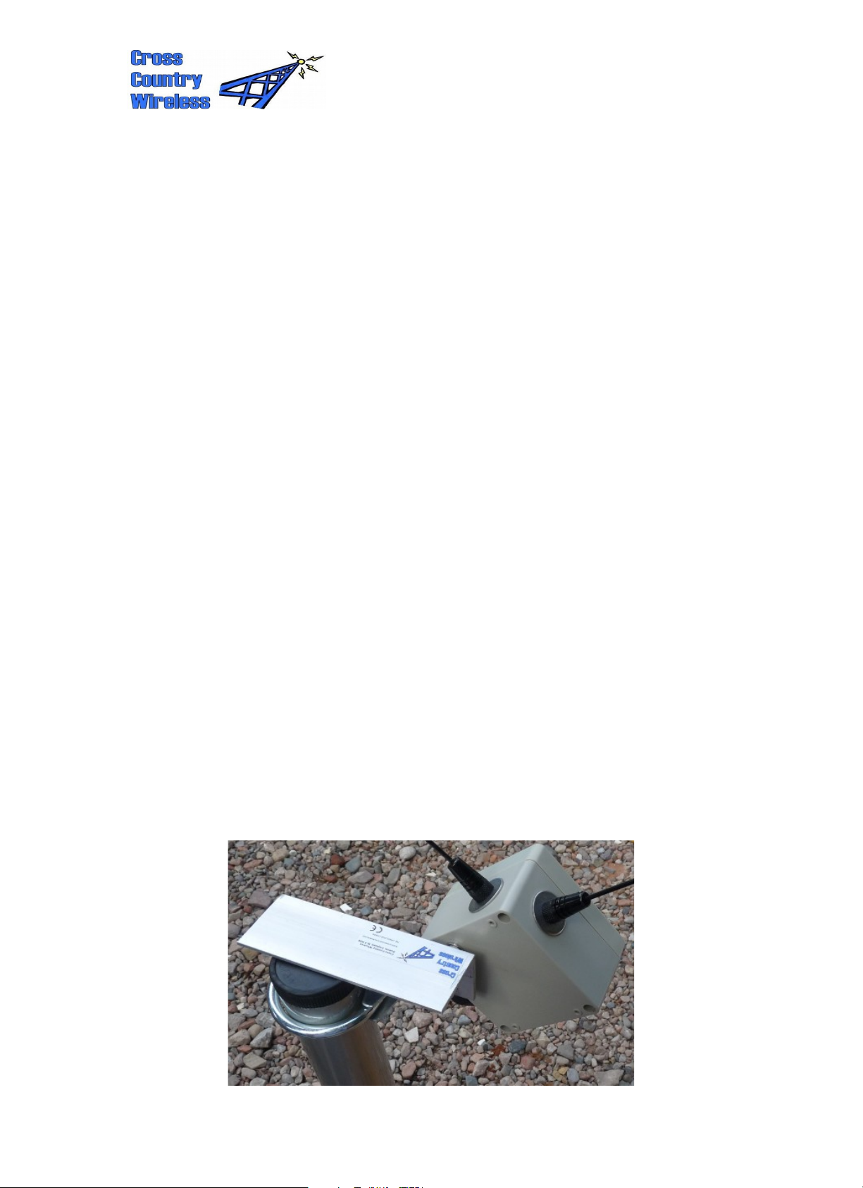
Install the whip elements in the antenna mounts using the allen key. Make sure
that the elements are securely fastened.
The head unit can be mounted onto a pole using the bracket and U bolt
assembly.
Remove the box lid with a Phillips or flat bladed screwdriver.
Loosen the cable gland to allow the RJ-45 connector to go through the gland.
Carefully connect the RJ-45 connector to the socket.
Slide the nitrile rubber sleeve into the cable gland and tighten the gland so that
the sleeve is securely gripped by the cable gland. There is no need to overtighten the gland to make a secure watertight seal.
Base unit
Remove the box lid with a Phillips or flat bladed screwdriver.
Loosen the cable gland to allow the RJ-45 connector to go through the gland.
Carefully connect the RJ-45 connector to the socket.
Slide the nitrile rubber sleeve into the cable gland and tighten the gland so that
the sleeve is securely gripped by the cable gland. There is no need to overtighten the gland to make a secure watertight seal.
Connect a 12 to 15 V supply to the 2.5mm DC power connector. The centre pin is
positive polarity.
The green LED should illuminate when power is applied. If the head unit is
connected to the far end of the cable the red LED will also illuminate.
Page 6
5 LEDs
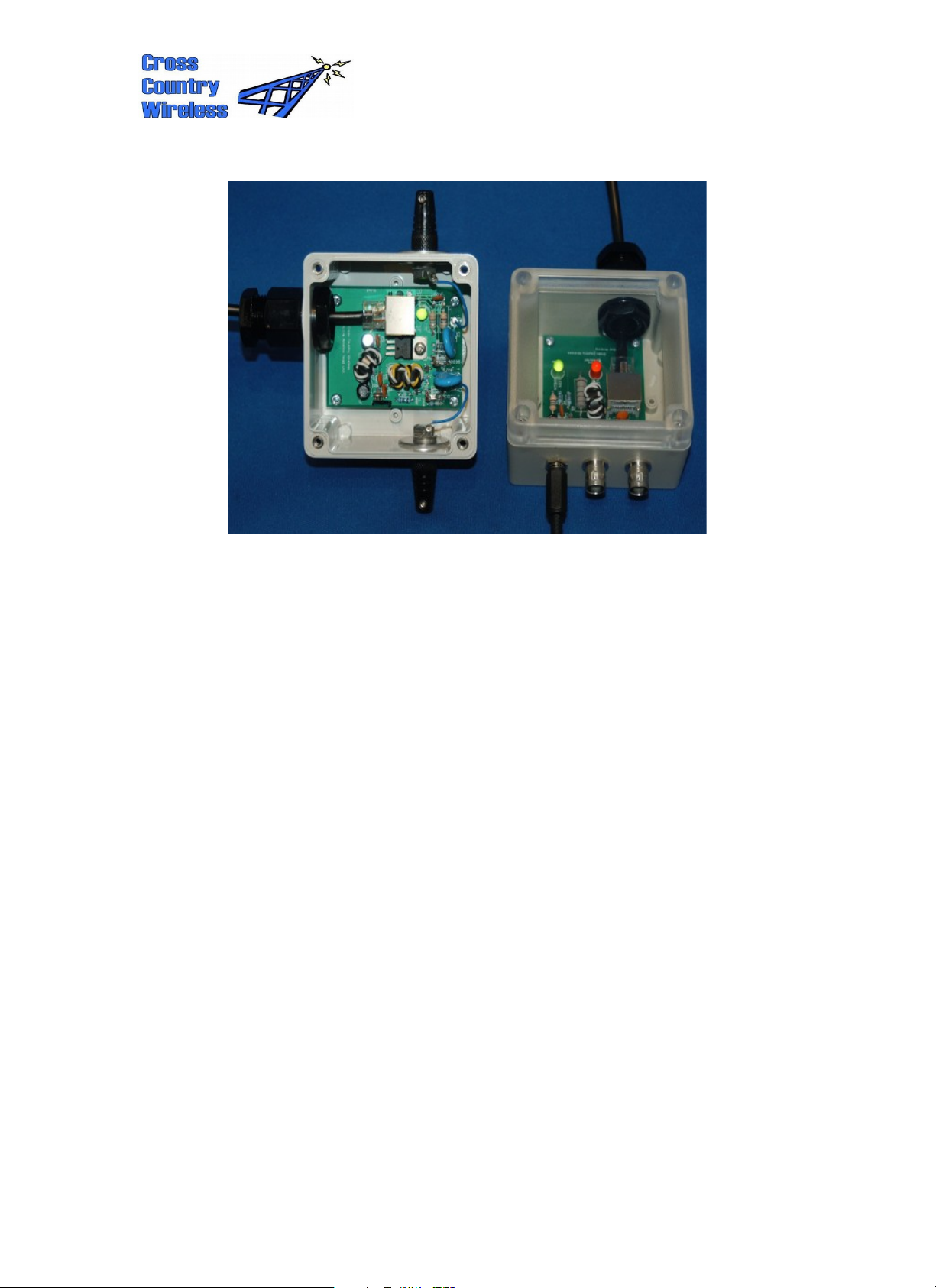
The base unit has two LEDs. The green LED is for DC power indication.
The red LED confirms that DC current is flowing to the head unit.
The head unit has a single green LED to confirm DC power during
installation.
Page 7
6 Ethernet cable
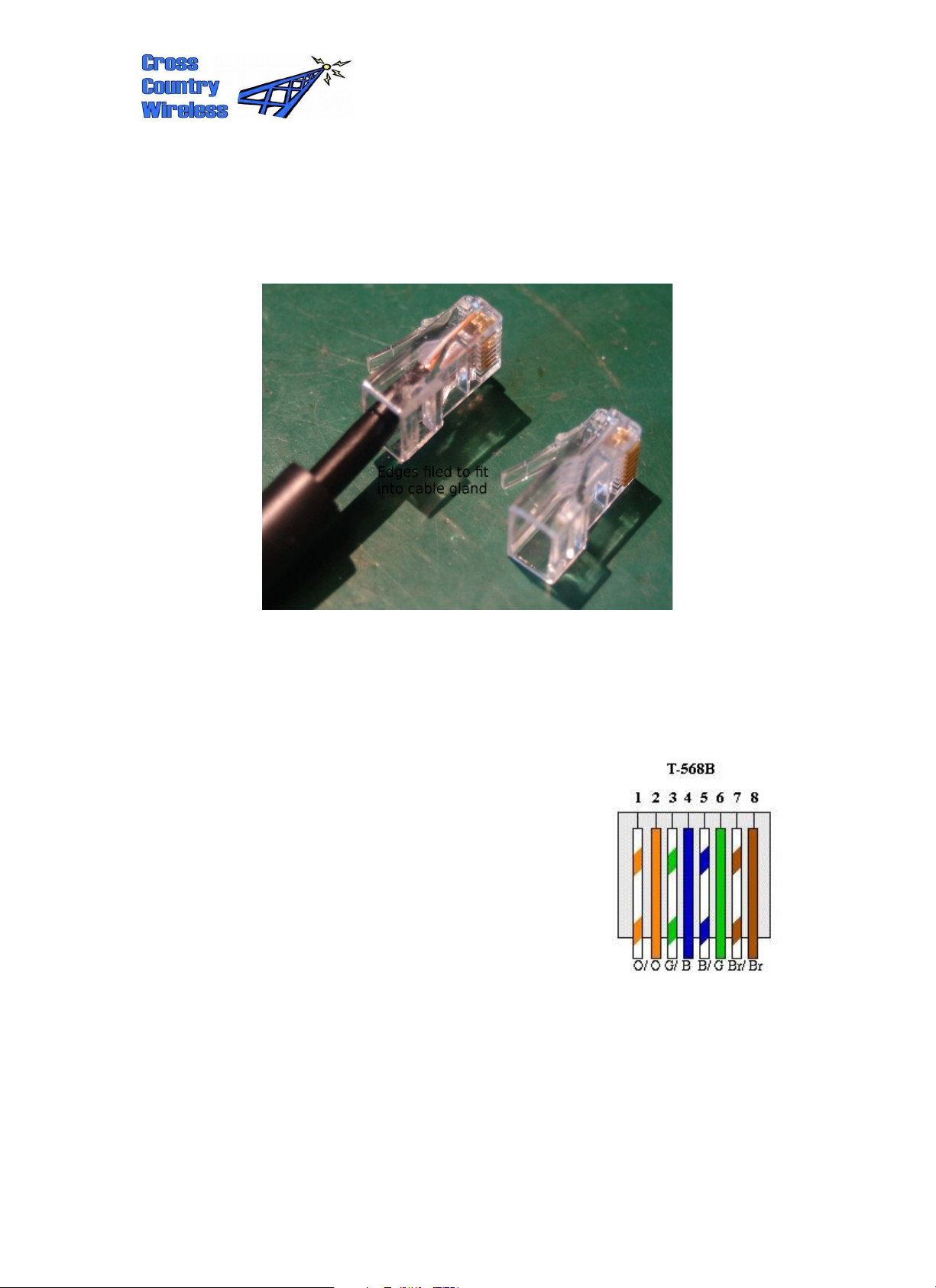
The ethernet cable supplied with the Active Antenna uses standard RJ-45
connectors.
The nitrile rubber sleeve used to seal the cable in the cable gland is :
Smooth nitrile fuel tubing hose Type A DIN 73379 5.4mm ID 9.4mm OD
The cable wiring is straight through to the T-568B colour code below.
Following tests with different types of cable we don't
recommend the use of shielded cable as the extra
capacitance caused extra losses at higher frequencies.
Page 8
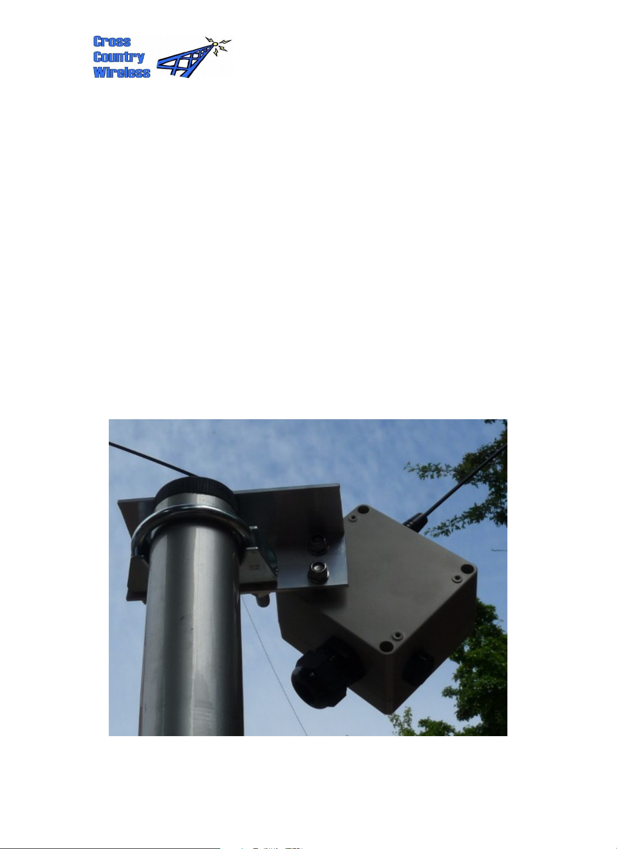
7 Suggestions for installation
The Active Antenna uses a balanced short upright vee dipole as a sensor for the
electric portion of the electromagnetic field.
Keep any nearby metal work as far away as possible.
If the antenna is mounted off the side of a tower keep the distance from the tower
to the antenna elements the same to ensure symmetry.
Mount the antenna as far away as possible from RF noise sources i.e. switch
mode power supplies, computers, phone chargers, electric fences.
The mounting height isn't too critical. If you have a choice of locations go for the
quietest location for RF noise rather than the strongest signal.
If mounting in a tree don't let any leaves or branches touch the antenna
elements. When they get wet they will unbalance the short dipole and may
reduce the antenna performance.
Due to the small size of the antenna look at possible locations as far away from
local RF noise sources as possible.
 Loading...