

Page 1
Revision: 3.0
Technical Manual
Date: Feb 7, 11
Technical Manual
www.crosscontrol.com
CCpilot XL
Page 2

CCpilot XL
Revision: 3.0
Technical Manual
Date: Feb 7, 11
www.crosscontrol.com
Contents
Contents .............................................................................................................................................2
1. Introduction ................................................................................................................................4
1.1. Identification .............................................................................................................................. 4
1.2. Care ............................................................................................................................................. 4
1.3. Environment and Environmental Tolerance ......................................................................... 4
1.4. Cleaning ...................................................................................................................................... 5
2. Overview ....................................................................................................................................6
2.1. CCpilot XL – Display unit ........................................................................................................... 6
2.2. CCpilot XL – PC unit .................................................................................................................. 6
2.3. Connecting the Display to the PC unit ................................................................................. 7
2.4. Connectors ................................................................................................................................. 7
3. Installation ..................................................................................................................................8
3.1. Placing and installing of the unit and peripherals .............................................................. 8
3.2. Mounting the PC unit separately ........................................................................................... 8
3.3. Mounting the display ................................................................................................................ 8
3.4. Integrated installation, PC unit mounted on display unit .................................................. 9
3.5. Mounting Cables ....................................................................................................................... 9
3.6. Connecting the Power supply ................................................................................................ 9
3.7. Heating via Preheating .......................................................................................................... 10
4. Basic operation ........................................................................................................................12
4.1. Function of the Display’s Push-buttons ................................................................................ 12
4.2. Starting Up................................................................................................................................. 12
4.3. Shutting-down .......................................................................................................................... 12
4.4. Touch screen ............................................................................................................................ 13
4.5. Back-up battery ....................................................................................................................... 13
5. External interface description ................................................................................................14
5.1. Power Supply Connector ....................................................................................................... 15
5.2. USB (USB 1, USB 2, USB 3, USB 4) ............................................................................................. 15
5.3. Ethernet (Ethernet) .................................................................................................................. 16
5.4. CAN (CAN1, CAN2) ................................................................................................................ 16
5.5. COM ........................................................................................................................................... 17
5.6. DMI - PC ..................................................................................................................................... 17
5.7. DMI - Display ............................................................................................................................. 18
5.8. Audio ......................................................................................................................................... 19
5.9. Video In (Video1, Video2) ..................................................................................................... 19
5.10. VGA Out ............................................................................................................................ 20
6. Software ....................................................................................................................................21
6.1. Operating System .................................................................................................................... 21
6.2. CCP settings ............................................................................................................................. 21
7. Specifications...........................................................................................................................23
7.1. Computer Core ....................................................................................................................... 23
7.2. Power supply ............................................................................................................................ 23
Page 3

CCpilot XL
Revision: 3.0
Technical Manual
Date: Feb 7, 11
www.crosscontrol.com
3
7.3. Display ....................................................................................................................................... 23
7.4. Environmental tolerance ....................................................................................................... 24
7.5. Weight and dimensions .......................................................................................................... 25
8. Technical Support ....................................................................................................................28
Trade Mark, etc. ..............................................................................................................................29
Index .................................................................................................................................................30
Page 4

CCpilot XL
Revision: 3.0
Technical Manual
Date: Feb 7, 11
www.crosscontrol.com
4
1. Introduction
In this technical manual you, as a user, a reseller or system integrator, will find important
information about CCpilot XL. The handbook will guide you and inform you about this on-board
computer’s technical possibilities and advantages.
This manual covers the standard models of CCpilot XL. The CCpilot XL platform is also available
additional configurations of hardware and software. Additional documentation can then be needed.
This material is copyright protected © 2010 CrossControl. All rights reserved.
1.1. Identification
There is a label on the back of the display and PC-unit of CCpilot XL. Printed on this labels are
numbers which identify your unique computer. During service and other contact with the supplier
it is important to be able to provide these numbers.
1.2. Care
All cables shall be disconnected from your CCpilot XL during welding or other service on
the machine where it is installed.
CCpilot XL shall only be mounted and serviced by authorised personnel. If the unit is
opened by unauthorised personnel, the normal guarantee will cease to be valid.
Scratches, or in the worst case damages, to the display occur easily if it comes in contact
with a sharp edge or hard material. In order to increase the longevity of the screen, this is
naturally something which should be avoided.
The unit can be damaged if it becomes too hot. Therefore, do not cover the unit by laying
things on it, for example hanging a jacket or other clothes on it.
Consider traffic safety when CCpilot XL is installed and whenever it is used. CrossControl
does not recommend that CCpilot XL or its accessories be used actively by the driver when
a risk of injury to people, or damage to property, is present.
Be advised that CCpilot XL draws power from the vehicle battery. This can result in the
inability of the vehicle to start if the onboard computer has been on for a period of time
without the vehicle motor running.
1.3. Environment and Environmental Tolerance
CCpilot XL has been designed to cope with tough environmental demands. Strict tests have been
conducted on the unit in order to ensure that it fulfils the expectations of a rugged unit and much
work has been performed to choose and design internal components so that they, under all
circumstances and in the best possible way, provide you with a dependable and user-friendly
working instrument. Within the chapter Specifications, a list of standards can be found according
to which CCpilot XL has been tested and approved.
CCpilot XL shall preferably be placed under a roof in order to prevent exposure to direct water
contact. It is also important that it is mounted securely on a stand or the like to inhibit the unit
from moving and thereby becoming damaged, damaging the vehicle and/or people during, for
example, a traffic accident.
Page 5

CCpilot XL
Revision: 3.0
Technical Manual
Date: Feb 7, 11
www.crosscontrol.com
5
1.4. Cleaning
To ensure proper and reliable functionality over time, the unit shall be wiped cleaned of dirt and
dust. Use a suitable light damp rag to clean the unit.
Never use alkaline, alcoholic or other chemicals for cleaning which can damage the unit.
Page 6
CCpilot XL
Revision: 3.0
Technical Manual
Date: Feb 7, 11
www.crosscontrol.com
6
2. Overview
CCpilot XL is a compact, robust and versatile on-board computer equipped with, among other
things, a pressure-sensitive touch screen as well as a large number of connection alternatives such
as CAN, COM, Ethernet and USB.
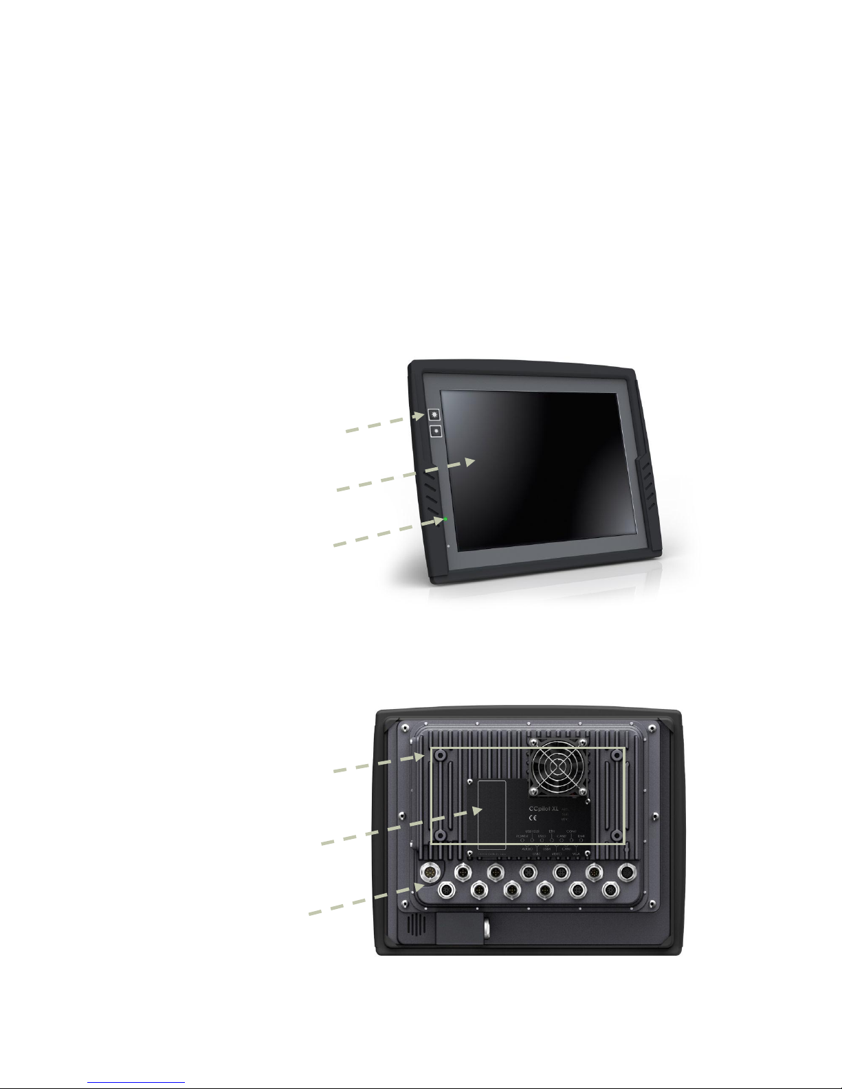
2.1. CCpilot XL – Display unit
On the display unit of CCpilot XL there are buttons for adjusting the screens brightness level and a
status indicator. Depending on the configuration of the display it may also be equipped with a
touch screen.
2.2. CCpilot XL – PC unit
CCpilot XL PC contains the processor unit and hard drive. It also provides easily accessible external
connectors.
Increase and decrease
display’s brightness level
Status indicator
Touch screen
External
Mounting holes
Brand Label and
Page 7
CCpilot XL
Revision: 3.0
Technical Manual
Date: Feb 7, 11
www.crosscontrol.com
7
2.3. Connecting the Display to the PC unit
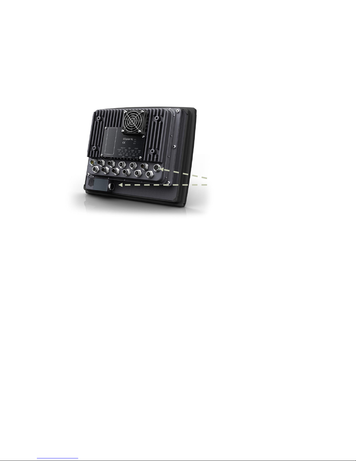
The display unit is connected to the PC unit with a DMI cable. The units can be mounted separately
or, as shown in the illustration below, as an integrated unit when combined with the 12.1” display.
The PC unit can also be configured to work with an external monitor using the VGA out signal or as
a standalone PC unit without any display.
2.4. Connectors
The connectors on CCpilot XL are M12 connectors, except from the display and power supply
connectors. Adapter cables are available as accessories, which make it possible to connect to
standard consumer peripherals connectors. For more information about each interface see the
chapter External interface description.
For more information on installing and setting up CCpilot XL see chapter Installation.
Display connectors
Page 8

CCpilot XL
Revision: 3.0
Technical Manual
Date: Feb 7, 11
www.crosscontrol.com
8
3. Installation
CCpilot XL must be installed in such a way that the unit is not exposed to any unnecessary stress or
present any traffic danger. In this section, some recommendations are made regarding installation.
For information about mounting accessories please contact your CCpilot XL reseller.
CCpilot XL shall only be serviced by authorized personnel. If the unit is opened by non-authorised
personnel, the warranty becomes void.
3.1. Placing and installing of the unit and peripherals
CCpilot XL shall be installed in a ventilated space where air is able to circulate around the unit,
therefore not near hot air vents or the like. There must be at least 50 mm distance between the unit
and the closest partition or any other barrier. If the unit becomes too warm, it may not perform to
its full capacity and, with high temperature, cease to function.
If the preceding instructions are not observed, the cooling of the unit can be degraded which can
lead to overheating, consequently causing permanent damage to the unit.
When CCpilot XL or any device is installed in a vehicle environment it is important that the
installation is traffic-safe. One should also avoid installing the unit where it will block the driver’s
view. This applies to both the instrument panel and the view through windshield. One should also
think about how the placement affects personal safety in the event of a collision.
Consider traffic safety whenever CCpilot XL is installed and used in vehicle installations.
CrossControl does not recommend that CCpilot XL or its accessories are used actively by the driver
or operator when a risk of injury to people, or damage to property, is present.
3.2. Mounting the PC unit separately
The PC unit should be fastened onto suitable panelling in the cabin or someplace similar. This is
done with the six mounting holes on the sides of the unit. Suitable fasteners, such as MRT M4x25
or MC6S M4x25 screws, can be used. The maximum tightening torque allowed is 1.0 Nm.
If the surface, on which the PC unit should be fastened, is not flat, care must be taken so as not to
put mechanical tension on the unit during fastening. This can be solved appropriately by placing
suitable spacers between the PC unit and the surface. An alternative solution is to use a separate,
flat mounting plate for the PC unit. This plate is first fastened onto the desired area with separate
screws, or by other means. Use thread lockers in all screw holes, e.g., Loctite 222.
We recommend installing CCpilot XL in such a way that it is not exposed to unnecessary vibration
or other stress.
3.3. Mounting the display
3.3.1. Bracket mount
CCpilot XL is preferably mounted on a convenient bracket which allows for adjustment of the
display’s position and angle. The bracket should have, or be provided with, a flat fastening plate to
which the unit is bolted. The 10.4” display has mounting holes according to VESA 75 and the 12.1”
display is according to VESA 100). To fasten, use appropriate M6 cap screw of type MC6S (Allen) or
MRT (Torx). Note that the enclosure has blind holes, which give a maximum thread depth in the
Page 9

CCpilot XL
Revision: 3.0
Technical Manual
Date: Feb 7, 11
www.crosscontrol.com
9
enclosure of 6.5 mm. The maximum torque is 2.5 Nm. Apply a thread locker in all bolt holes, e.g.
Loctite 222.
3.3.2. Panel Mount
With a front-mounted installation, use the rubber mask as a seal against the panel plate. The unit is
locked down by applying clamps which are either fixed to the panel (recommended) or fixed to the
unit through holes for VESA installation.
3.4. Integrated installation, PC unit mounted on display unit
An integrated installation can only be carried out on the PC unit together with the 12.1” display
unit.
The same placing demands apply here, as when the units are mounted separately. Mounting,
however, is carried out somewhat differently.
To fasten the PC and display units together, screws of type MC6S (Insex) or MRT (Torx), M4 x 25,
should be used. The maximum tightening torque allowed is 1.0 Nm. Use thread lockers in all screw
holes, e.g., Loctite 222.
The mounting holes on the PC unit’s cooling flanges are used to screw the integrated unit onto a flat
mounting plate. The mounting holes have M6 dimensions and are blind holes with a depth of 10
mm. Use screws of the correct length so that they do not hit the bottom of the mounting holes, and
always use thread lockers in all screw holes, e.g., Loctite 222. Maximum tightening torque allowed
is 9.8 Nm.
Note that the mounting plate, which is screwed onto the cooling flanges, should not cover a large
area. This may cause poor cooling of the computer and damage it permanently.
If the screws used in the mounting holes hit the bottom, it may cause damage to the unit’s
enclosure.
3.5. Mounting Cables
Cables shall be installed so that they don’t run the risk of being damaged, pinched or worn. Strain
relief cable assemblies and avoid bending and twisting cables. The connectors shall always be
screwed-in securely to give good contact and avoid unnecessary strain.
Through adapter cables, as supplied by CrossControl, standard connectors for Ethernet, USB and
COM can be connected to the unit. The hook up of these adapter cables can and should be placed in
a moisture-free, hidden space and should be secured and strain-relived.
3.6. Connecting the Power supply
This instruction addresses vehicle installations but the principle is the same also for other types of
installations. See also the description for the Power Supply Connector pin outs under the section
External interface description.
Carefully follow the connection instructions below. Make sure that the contacts are the right way up
and that they do not have to be forced, but lock gently and pliant.
Page 10
CCpilot XL
Revision: 3.0
Technical Manual
Date: Feb 7, 11
www.crosscontrol.com
10
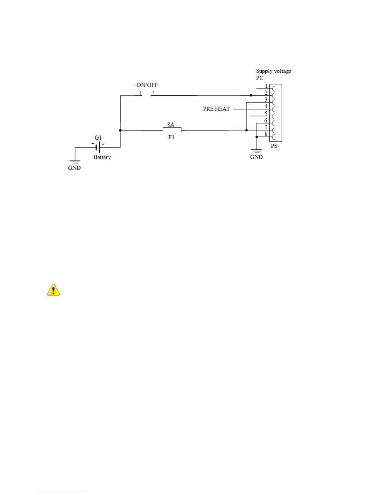
GND is connected to the vehicle’s ground.
ON/OFF (pins 2 and 5) i.e. the computer’s ON/OFF signal is connected to the battery or power
source through a recoiling ON/OFF button.
Battery (pins 3 and 7), i.e. the computer’s power supply (+24 VDC), should be connected directly to
the vehicle’s battery (G1) through an 8A fuse (F1).
Preheating (pin 4) allows preheating of the hard disk.
By connecting the power supply according to above, the on-board computer will start by a short
push signal on the ON/OFF button, equal to starting a normal PC computer. To shut down CCpilot
XL, push the ON/OFF button again or use the operating system shut down functionality.
3.6.1. Precautions
If applicable connect the computer before any main switch, as per the illustration above. If this is
not possible, ensure that the computer is turned off using for example the on/off button or turnkey
functionality before turning off the main switch or in any other way making the computer
powerless.
Sudden power disruptions may cause the computer to shut down, potentially causing lost or
corrupt data. If for example the power fluctuates when starting the vehicle engine, the computer
should be started after the vehicle engine is running.
Ensure that any application data is saved before turning off the computer.
All cables shall be disconnected from your computer before any welding or other service action is
performed on the vehicle.
3.7. Heating via Preheating
Preheating can be used to prepare for a direct start-up of CCpilot XL in low temperatures.
Preheating is initiated by a signal, from an external device, e.g., timer or motor heater, into pin 4 in
the power supply contact on CCpilot XL. When the signal is high the temperature is continuously
checked. If the temperature is below the defined setting the heater element is activated, by default
+5 °C. To save battery power, the LED indication and display is not activated during preheat
function.
Page 11

CCpilot XL
Revision: 3.0
Technical Manual
Date: Feb 7, 11
www.crosscontrol.com
11
The table below shows the time before the unit starts up at different temperatures using the default
settings. External factors may affect the values; use them as an approximate guidance.
-40˚C
-30˚C
-20˚C
-10˚C
Compact Flash
3 min
<1 min
0
0
HDD
20 min
15 min
10 min
5 min
Note that preheating consumes energy from the vehicle’s battery. This can result in the vehicle not
starting, after prolonged preheating of the PC and display, due to a flat battery.
Page 12

CCpilot XL
Revision: 3.0
Technical Manual
Date: Feb 7, 11
www.crosscontrol.com
12
4. Basic operation
This section covers basic operation of CCpilot XL unit such as start-up and shut down.
4.1. Function of the Display’s Push-buttons
In the top left of the CCpilot XL display there are two buttons to control the screen brightness.
Press and hold the button to gradually increase or decrease the display’s brightness.
4.2. Starting Up
The unit is started by sending a short push signal to the ON/OFF pins in the power connector on
CCpilot XL. For more information see the chapter connecting the Power Supply.
4.2.1. Starting in the cold
Rotating hard drives should not be used in low temperature. To prevent damage, the temperature
of the hard drive is checked and if needed warmed before start-up.
CCpilot XL will not start immediately when sending the ON/OFF signal and the temperature is
lower than +5°C (+41°F). Instead, an internal heater will warm up the hard drive. During warm up
the LED on the display will flash and the display will be activated.
Once the temperature for the hard disk is above +5°C, CCpilot will start automatically. The heater
continues to warm the hard drive until it reaches +14°C.
To prepare for a fast start up in low temperatures preheating can be used. For more information see
chapter, Heating via Preheating.
Values for the temperatures mentioned above are default values but can be changed from the CCP
Settings program.
4.3. Shutting-down
To ensure that data does not get lost or the hard disk become corrupt, it is recommended that all
programs are closed before the unit is shut down.
CCpilot XL can be shut down either from the operating system or from a short push signal on the
ON/OFF input in the power connector.
4.3.1. Forced shut-down
Setting the ON/OFF signal high for 5 seconds will perform a forced shut down. The forced shut
down is a direct shut down of the computer without the control of the operating system. This shut
down should normally be avoided and only be used when the computer is not responding to normal
shut down.
Note that any information which was not saved will now be lost.
Page 13

CCpilot XL
Revision: 3.0
Technical Manual
Date: Feb 7, 11
www.crosscontrol.com
13
4.4. Touch screen
The CCpilot XL display is equipped with a touch screen which gives the opportunity to provide an
easy-to-use HMI (Human Machine Interface) for the user.
4.4.1. Double and right click on the touch screen
To perform the equivalent to a right click on the touch screen first tap the place where the right
click is supposed to be pressed and then tap the screen again slightly to the side of the initial tap.
To perform a double click on the touch screen, tap the screen twice in the same place.
4.4.2. Calibration of touch screen
If needed the touch screen can be calibrated. Calibration is started manually via the CCP Settings
application. To keep the calibration data the administrator login must be done in CCP Settings.
Be thorough with this calibration for the best possible performance with your touch screen. You
should use the same object (finger, stylus) during calibration which you think you will use later.
Don’t use sharp or pointed objects on the touch screen since these can damage or scratch it, which
can seriously degrade its functionality.
4.5. Back-up battery
Time and date information on CCpilot XL is stored in a memory sustained by a back-up battery.
This battery has a limited life time and must therefore be exchanged at regular intervals. The life
time of the battery is approximately 3 years.
4.5.1. Exchanging the back-up battery
The battery is located on the hard-drive circuit board accessible behind the hatch on the side of the
computer module. Perform the steps below to exchange the battery.
Before performing the battery exchange make sure that the PC is disconnected from power and any
other connections.
1. Remove the two screws on the plate covering the HD-module
2. Carefully remove the plate
3. Pull out the HD-module using a suitable tool inserted in the two holes on the HD-module
4. Remove the battery from the battery holder
5. Insert a new battery. Type: BR1632 (3V)
6. Carefully push the HD-card back into the PC-unit. Make sure that the HD-module is
inserted correctly.
7. Put back the plate and the screws.
Page 14
CCpilot XL
Revision: 3.0
Technical Manual
Date: Feb 7, 11
www.crosscontrol.com
14
5. External interface description
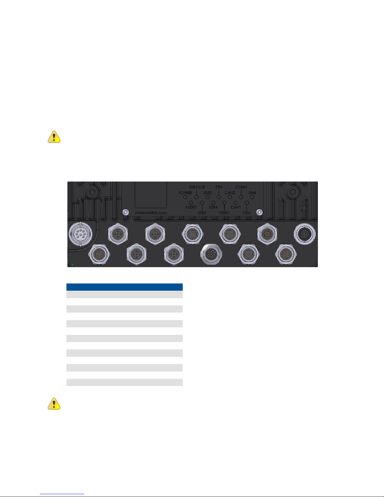
Accessible on the rear of CCpilot XL, there are a number of ports to connect various peripheral
equipments. In order to give CCpilot XL its high environmental classification, the unit is equipped
with DIN M12 connectors. CrossControl provides adapter cables which convert from DIN M12 to
standard connectors.
Use caution and avoid plugging/unplugging of connectors when the computer is on. If the pins
become bent or damaged they may not function correctly, or in the worst case, the onboard
computer or other equipment may be damaged.
The connector legend describes where the connectors are located on your unit. The connectors
available is dependent on the unit’s configuration, therefore connections can be addressed which
may not be available to your unit.
Position
Description
X1
Power Supply
X2
Audio
X3
USB 1
X4
USB 2
X5
USB 3
X6
USB 4
X7
Ethernet
X8
Video In
X9
CAN 2
X10
CAN 1
X11
COM
X12
VGA out
X13
DMI
Notice that the following connector descriptions are those which are located on the unit, not those
that the attached cables shall have in order to mate with them.
Page 15
CCpilot XL
Revision: 3.0
Technical Manual
Date: Feb 7, 11
www.crosscontrol.com
15
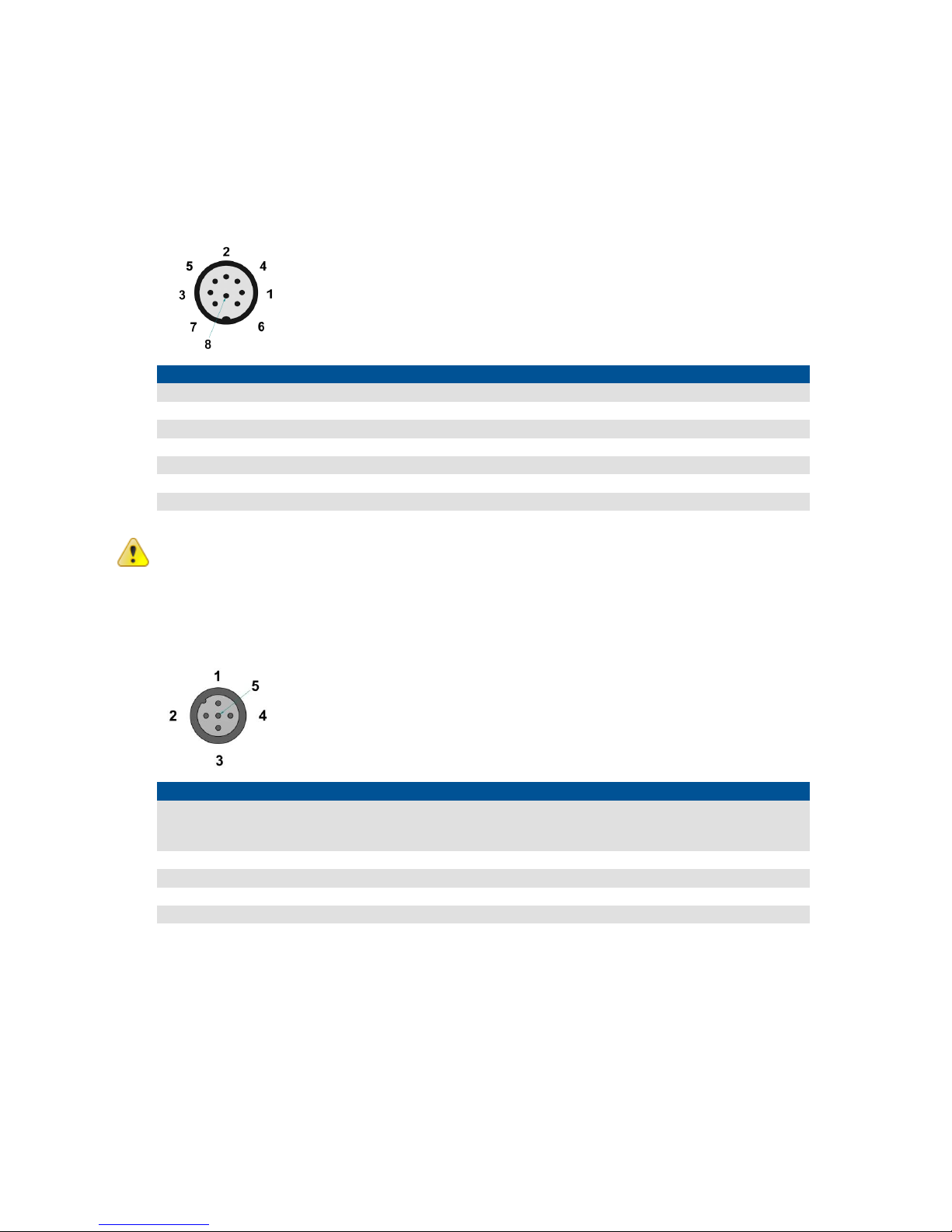
5.1. Power Supply Connector
Marking: POWER IN
Connector Type: Serial 723 8 Pin, male
Pin
Signal
Description
Comments
1
NC Not connected
2
Don
PC on
10-36 V = PC on
3
Dpow
Unswitched power
4 Preheating
Signal to starts preheating of HD
5
Don
PC on
10-36 V = PC on
6
GND
Ground
7 Dpow
Unswitched power
8 GND
Ground
For complete hook up instructions, see the section entitled Installation.
5.2. USB (USB 1, USB 2, USB 3, USB 4)
Marking: USB 1, USB 2, USB 3 and USB 4
Connector Type: DIN M12, 5-pole, A-coded, male
Pin
Signal
Description
Comments
1
Vbus
Power to external USB-unit
5 Volt, max 2A for USB 1 and max 500 mA
for USB 2-4. Internal over current and
shortcut protected.
2
D-
Data
3 D+
Data
4 NC Not connected
5
GND
Ground reference
Via the USB port, you can connect a multitude of devices to CCpilot XL. For some devices, drivers
compatible with the operating system are required to be installed in order for the device to
function.
The USB ports follow the USB 2.0 standard. Due to data communication safety in rough
environments three of the four available USB connectors is limited to full speed (up to 12 Mbps). If
high speed is necessary (up to 480 Mbps) the device must be connected to the USB 1.
USB connector 1 can supply up to 2A, USB 2-4 can supply up to 500mA each. The total current of
all USB ports 1-4 has a max of 2A. The USB ports are internal over current and shortcut protected.
An eventual cable shield is connected to the M12 connectors cover.
Page 16
CCpilot XL
Revision: 3.0
Technical Manual
Date: Feb 7, 11
www.crosscontrol.com
16
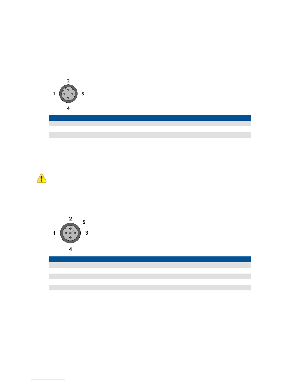
5.3. Ethernet (Ethernet)
Marking: Ethernet
Connector Type: DIN M12 4-pole, D-coded, female
Pin
Signal
Description
Comments
1
TX+ 2 RX+ 3 TX- 4 RX-
With an Ethernet connection, CCpilot XL can access other units and networks. The Ethernet
connector support 10/100 Mbps, i.e. communication speed up to 100 Mbps.
If shielded Ethernet cable is used the cable shield is connected to the M12 connectors cover.
Be aware that connecting CCpilot XL to a network environment can impose a security threat.
5.4. CAN (CAN1, CAN2)
Marking: CAN 2 and CAN 1
Connector Type: DIN M12, 5-pole A-coded, female
Pin
Signal
Description
Comments
1
CAN1 SHLD
2
NC
No connection
3 CAN GND
4
CAN1 H
CAN1 High
5 CAN1 L
CAN1 Low
It is possible to connect two CAN-channels to CCpilot XL to connect a control system or, for
example, the FMS system in a vehicle.
The interface has a PCA82C251 high speed transceiver installed and follows the ISO 11898-24V
standard. Alternatively CCpilot XL CAN2 port can be equipped with the fault tolerant TJA1054AT
transceiver.
Page 17

CCpilot XL
Revision: 3.0
Technical Manual
Date: Feb 7, 11
www.crosscontrol.com
17
Pinning of the CAN connector is according to the CANopen standard. The CAN connectors do not
provide power out to external units. There is no termination in the interface; therefore, this shall be
present in the cable.
CrossControl is well-experienced with control via the CAN-interface and both software and drivers
are tested in various environments and under different conditions. Contact CrossControl if you
need more information about our CAN-solutions.
5.5. COM
Marking: COM
Connector Type: DIN M12, 8-pole, A-coded, male.
Pin
Signal
Description
Comments
1
DCD
Data Carrier Detect
2 RxD
Receive data
3 TxD
Transmit data
4 DTR
Data Terminal Ready
5 GND
Signal reference
6
DSR
Data Set Ready
7
RTS
Request To Send
8 CTS
Clear To Send
The COM port follows the RS232 standard except for the “Ring Indicator” signal, which has been
omitted. The supported communication speed for these ports is 2.4 to 115.2 kbps. An eventual cable
shield is connected to the M12 connectors cover.
5.6. DMI - PC
Marking: DMI
Connector Type: Lemo, female.
Pin
Signal
Description
Comments
1
TXOUT0-
LVDS
2 TXOUT0+
LVDS
3 TXOUT1-
LVDS
4 TXOUT1+
LVDS
5 TXOUT2-
LVDS
6 TXOUT2+
LVDS
7 TXCLK-
LVDS
8 TXCLK+
LVDS
9 DMI power supply
+24 V
10
TFT_ON
TFT power control
11
Beeper
Simple sound unit
12
TS_Tx
Touch screen Tx
13
TS_Rx
Touch screen Rx
Page 18

CCpilot XL
Revision: 3.0
Technical Manual
Date: Feb 7, 11
www.crosscontrol.com
18
14
SPI_MISO
SPI data Display-PC
15
RESET AVR
Reset input to AVR
Low in, while programming AVR. No
connection in the cable
16
SPI_MOSI
SPI data Display-PC
17
SPI_CLK
SPI clock Display-PC
18
ON_OFF_2
On/off button from display
to the PC
Not implemented
19
GND
Ground reference
The DMI cable handles display and control signals between the CCpilot XL Display and PC-unit.
The maximum recommended DMI cable length is 5.5 m.
Outer cable shield and LCDS double-shield is connected to the connector cover.
For information concerning the DMI connector on the display see chapter DMI - Display.
5.7. DMI - Display
Marking: DMI
Connector Type: Lemo, female.
Pin
Signal
Description
Comments
1
TXOUT0-
LVDS
2 TXOUT0+
LVDS
3 TXOUT1-
LVDS
4 TXOUT1+
LVDS
5 TXOUT2-
LVDS
6 TXOUT2+
LVDS
7 TXCLK-
LVDS
8 TXCLK+
LVDS
9
DMI power supply
+24 V
10
TFT_ON
TFT power control
11
Beeper
Simple sound unit
12
TS_Tx
Touch screen Tx
13
TS_Rx
Touch screen Rx
14
SPI_MISO
SPI data Display-PC
15
RESET AVR
Reset input to AVR
Low in, while programming AVR. No
connection in the cable
16
SPI_MOSI
SPI data Display-PC
17
SPI_CLK
SPI clock Display-PC
18
ON_OFF_2
On/off button from display
to the PC
Not implemented
19
GND
Ground reference
20
VGA R
VGA Red
21
VGA G
VGA Green
22
VGA B
VGA Blue
23
H Sync
Horizontal Sync
24
V Sync
Vertical Sync
25
VGA enable
Put to gnd when enabled
26
GND VGA
Ground reference
The DMI cable handles display and control signals between the CCpilot XL Display and PC-unit.
The maximum recommended DMI cable length is 5.5 m.
Page 19

CCpilot XL
Revision: 3.0
Technical Manual
Date: Feb 7, 11
www.crosscontrol.com
19
Outer cable shield and LCDS double-shield is connected to the connector cover.
For information concerning the DMI connector on the PC unit see chapter DMI - PC.
5.8. Audio
Marking: Audio
Connector Type: DIN M12, 8-pole, A-coded, female.
Pin
Signal
Description
Comments
1
Line out L
2
Line out R
3
GND (Speaker)
Shield in cable
4
Microphone
5
Mic. Ref.
Microphone reference
6
Speaker output L
Amplified
7
Speaker output R
Amplified
8
GND (Line out)
Shield in cable
The audio offers possibilities to play everything from warning sound to music directly from CCpilot
XL two channel speaker stereo output. The output offers both line out signal and amplified speaker
out. Microphone in is also available for sound recording or to present the sound from, for example,
cameras.
Volume is set by the volume controls within Windows.
5.9. Video In (Video1, Video2)
Marking: VIDEO
Connector Type: DIN M12, 5-pole, B-coded, male.
Pin
Signal
Description
Comments
1
GND
GND Video A
2 Video A
PAL/NTSC input A
3 Video B
PAL/NTSC input B
4
12V_OUT
Power out +12 V
Power supply to video camera, Max
300 mA
5
GND
GND Video B
Page 20

CCpilot XL
Revision: 3.0
Technical Manual
Date: Feb 7, 11
www.crosscontrol.com
20
The Video connector has two composite video inputs for the attachment of video sources such as
rear view cameras. It supports PAL, the European video format, as well as NTSC, the American
standard.
The video connector can be used to power external cameras using the 12V unfiltered supply. The
output has a current limit that depends on the internal unit temperature. The current is limited to
0.150A at an internal unit temperature of 70 degrees Celsius and around 0.2A in normal working
conditions.
The cable which is used to connect the camera to the computer shall be a 75-Ω coaxial cable, e.g.
M17/94-RG179. An eventual outer cable shield is connected to the M12 connectors cover.
Ensure that there is no DC-offset (supply current) on the video signal connected since this can
cause damage to your CCpilot XL.
5.10. VGA Out
Marking: VGA
Connector Type: DIN M12, 8-pole, A-coded, female.
Pin
Signal
Description
Comments
1
VGA R
VGA Red
2 VGA G
VGA Green
3 VGA B
VGA Blue
4 H Sync
Horizontal Sync
5 V Sync
Vertical Sync
6 GND R
Ground reference Red
Shield on VGA Red cable
7
GND G
Ground reference Green
Shield on VGA Green cable
8
GND B
Ground reference Blue
Shield on VGA Blue cable
The VGA out can be used as external displays to the CCpilot XL PC unit, either as a stand-alone
head display or as dual display together with the CCpilot XL display.
Outer cable shield is connected to the cable connector cover.
Page 21
CCpilot XL
Revision: 3.0
Technical Manual
Date: Feb 7, 11
www.crosscontrol.com
21
6. Software
This section gives a short description to some of the computer specific software supplied with
CCpilot XL.
6.1. Operating System
CCpilot XL is by default supplied with Windows XP and the following described software tools
targets Windows users. CCpilot XL can also be used with other operating systems, contact your
sales representative for more information.
CCpilot XL offers a multitude of connection alternatives, for instance via USB. In order for the
device connected to CCpilot XL to function correctly, sometimes drivers must be installed.
CrossControl can only guarantee the function for applications and devices which are tested and
approved by CrossControl.
6.2. CCP settings
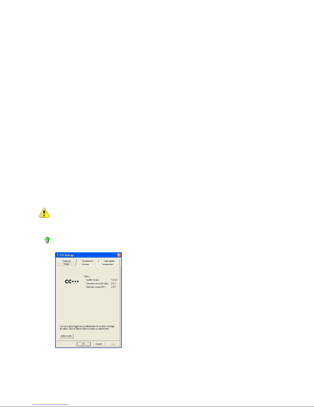
CCP settings is a software to view and configure CCpilot XL specific parameters and settings.
Changes to the parameters are not performed unless an administration login is made into CCP
Settings. Also, many of the settings require administration privileges on the computer to be able to
store the settings. The login is made from the Status tab in CCP Settings and the password is
CCPILOT.
CrossControl does not take any responsibility for any resulting damage or injury given as a result of
reconfiguring CCP settings.
6.2.1. Open CCP Settings
CCP settings is opened either from the Control panel or from the light bulb icon located in the
status notification area in the task bar.
Page 22

CCpilot XL
Revision: 3.0
Technical Manual
Date: Feb 7, 11
www.crosscontrol.com
22
6.2.2. CCP setting status
The colour of the light bulb indicates the CCP setting status.
RED – Not active. The CCP settings service is not started or something is wrong in the
communication with the computer. Within this state the display led and push buttons are not in
communication with the PC unit and therefore not functional.
YELLOW – Active and waiting. The CCP settings service is in idle state.
GREEN – Busy. The CCP settings service is operating with the computer.
6.2.3. The Status tab
The status tab presents information about the firmware versions loaded on the unit.
The status tab also has an administrator login button. The administrator login gives access to more
parameters.
6.2.4. The general tab
From the general tab it is possible to alter the steps for the dimming buttons. It is also possible to
assign other functionality than dimming of the backlight to the dimming buttons.
6.2.5. The temperature tab
The temperature tab gives status information about the unit’s internal temperature as well as
information regarding the temperature control functions.
6.2.6. The shut-down tab
From the shut-down tab it is possible to configure how the computer handles shut down procedure.
6.2.7. The touch-screen tab
The touch-screen tab offers calibration of the touch screen functionality.
Page 23

CCpilot XL
Revision: 3.0
Technical Manual
Date: Feb 7, 11
www.crosscontrol.com
23
7. Specifications
The specification may vary depending on your computer configuration.
7.1. Computer Core
Core Component
Description
Comments
Processor
Intel Pentium Core Duo, 1,6 GHz
Storage
Compact Flash (8 GB to
16 GB) or rotating hard disk (2”5,
40 GB) exchangeable via hatch on
enclosure
40 GB rotating disc default.
RAM
2048 MB SDRAM
Interface
Description
Comments
CAN
2 pcs. 2.0B, ISO 11898 – 24V,
PCA82C251 transceiver,1 Mbit
Optional: TJA1054AT - fault
tolerant transceiver
USB
4 pcs.
Ver. 2.0, 3 full speed,
1 high speed
Video in
2 pcs.
Zoomed composite video signal
RS232
1 pcs.
<= 115 000 baud
Ethernet
2 pcs.
10/100 Base-T
Touch screen
Resistive Touch screen
8-wire
Audio
Line out
Speaker out
Mic in
1V RMS at 10k
4W/channel at 4Ω
VGA out
1pcs
Dual screen or dual display
DMI
1 pcs
VGA out and display signals
7.2. Power supply
Power Supply
Description
Comments
Supply Voltage
24 V nominal
Power Consumption
< 2A at 24 V
7.3. Display
Display
Description
Comments
10”4
Colour, XGA, 320 cd/mm*
Aspect Ratio 4:3
12”1
Colour, XGA, 320 cd/mm*
Aspect Ratio 4:3
Page 24
CCpilot XL
Revision: 3.0
Technical Manual
Date: Feb 7, 11
www.crosscontrol.com
24
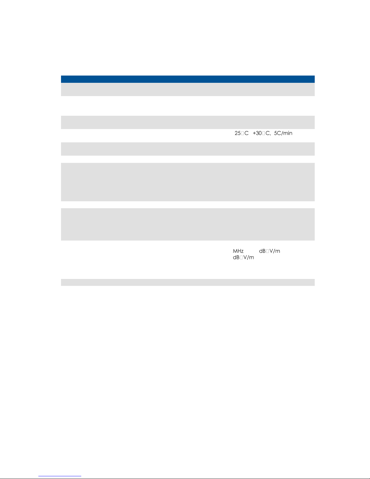
7.4. Environmental tolerance
Environmental Test
Standard
Dry Heat
IEC 60068-2-2 Bd
Operating: +55°C, 24h
Storage: +60°C, 24h
Damp Heat
IEC 60068-2-30 Db
Operation: +25°C / +55°C
>93% RH 6*24h
(without touch screen)
Cold
IEC 60068-2-1 Ad
Operating: -25°C, 24h
Storage: -40°C, 24h
Change of temperature
IEC 60068-2-14 Nb
- -
3hr hold time, 20 cycles
Vibration
IEC 60068-2-64
0,01 g2/Hz 10-200 Hz
1,39g (RMS) 3x0,5h
Shock
IEC 60068-2-29
5 g / 11 ms 3x ±1000 bumps
EMC Electrical Transient
ISO 7637-2
Pulse 1: -50V /2mS
2: +25V /2mS
3a: -220V /1mS
3b: +220V /1mS
4: -5V
5: +70V
EMC Immunity, ESD
EN 61000-4-2
8 kV air, 6 kV contact
EMC Immunity, RF
ISO 11452-2
ISO 11452-4
RF electromagnetic field
200-1000MHz 30V/m 80%AM
Bulk Current Injection
20-200MHz 60mA 80%AM
EMC Emission
ISO 14982
Narrowb. Broadb.
30-75 54-44 64-54
75-400 44-55 54-65
400-1000 55 65
Enclosure
EN 60529
IP54
The tests are performed with 24 V power level. The environmental tolerance may be affected by
external factors like mounting, cables, etc.
Page 25
CCpilot XL
Revision: 3.0
Technical Manual
Date: Feb 7, 11
www.crosscontrol.com
25
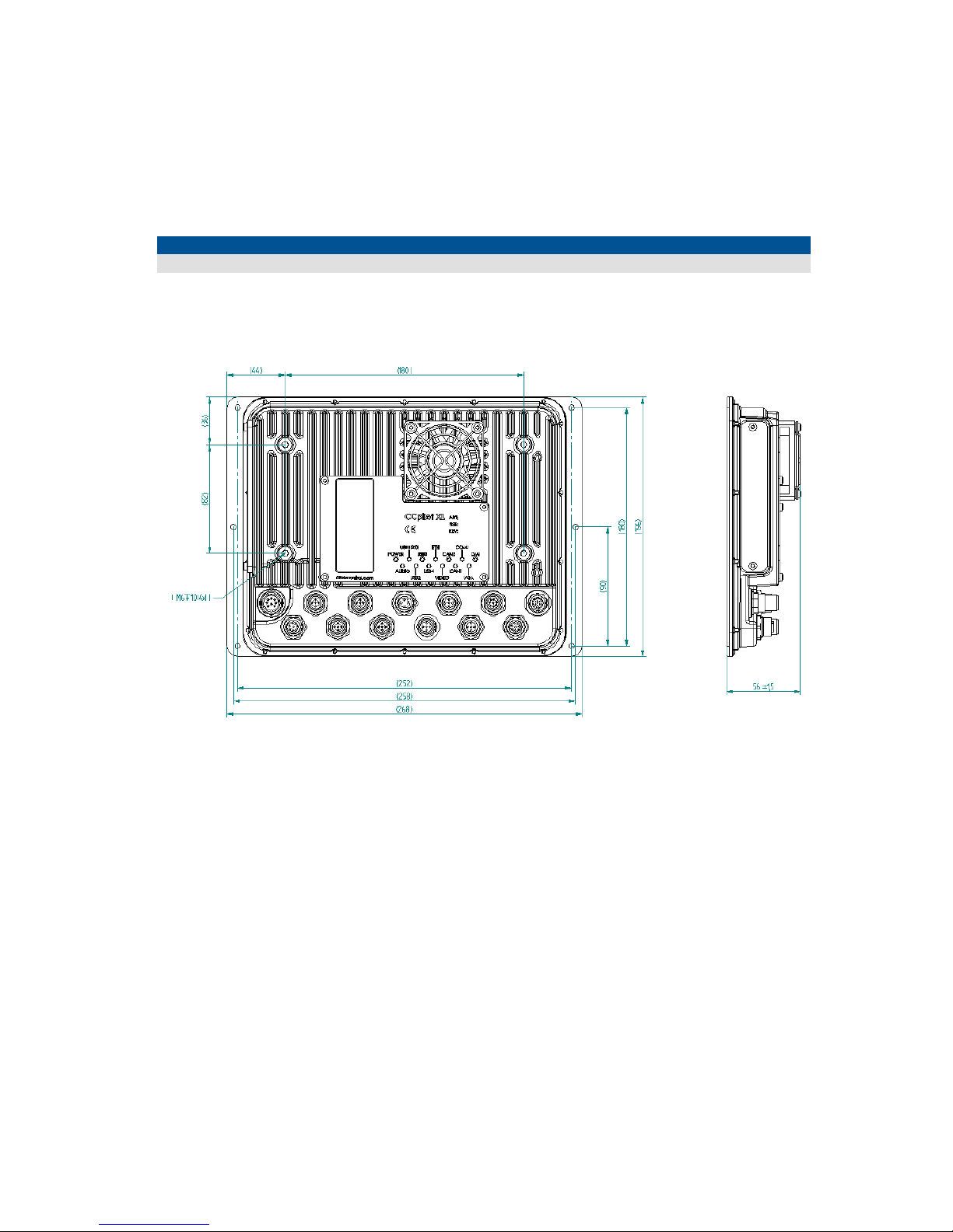
7.5. Weight and dimensions
7.5.1. PC unit
Description
Comments
Enclosure size
268 x 196 x 56 mm (W x H x D)
Page 26
CCpilot XL
Revision: 3.0
Technical Manual
Date: Feb 7, 11
www.crosscontrol.com
26
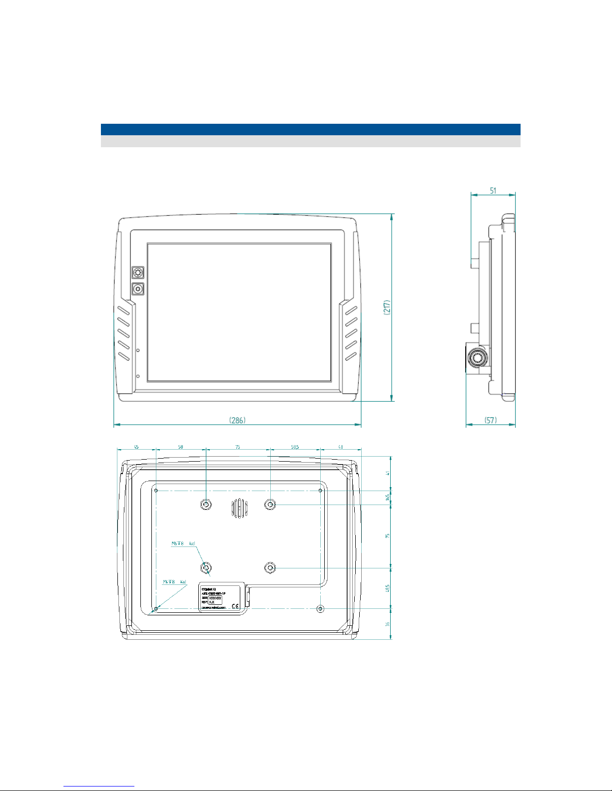
7.5.2. 10.4” Display
Description
Comments
Enclosure size
286 x 217 x 57 mm (W x H x D)
Page 27
CCpilot XL
Revision: 3.0
Technical Manual
Date: Feb 7, 11
www.crosscontrol.com
27
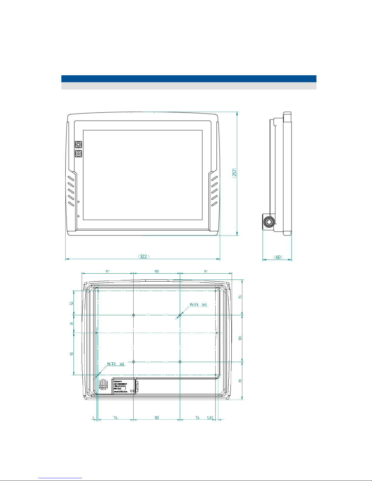
7.5.3. 12” Display
Description
Comments
Enclosure size
322 x 257 x 60 mm (W x H x D)
Page 28

CCpilot XL
Revision: 3.0
Technical Manual
Date: Feb 7, 11
www.crosscontrol.com
28
8. Technical Support
Contact your reseller or supplier for help with possible problems with your CCpilot XL. In order to
get the best help, you should have your CCpilot XL in front of you and be prepared with the
following information before you contact support.
Part number and serial number of the unit, which you find on the brand label
Date of purchase, which is found on the invoice
The conditions and circumstances under which the problem arises
Possible error messages which are shown.
Version number of the operating system, which you find via the Start menu: go to the
Control Panel and click on System.
Information regarding possible external equipment which is connected to CCpilot XL.
Page 29

CCpilot XL
Revision: 3.0
Technical Manual
Date: Feb 7, 11
www.crosscontrol.com
29
Trade Mark, etc.
© 2010 CrossControl AB
All trademarks sighted in this document are the property of their respective owners.
CCpilot is a trademark which is the property of CrossControl AB.
Intel is a registered trademark which is the property of Intel Corporation in the USA and/or other
countries. Linux is a registered trademark of Linus Torvalds. Microsoft and Windows are registered
trademarks which belong to Microsoft Corporation in the USA and/or other countries. CANopen is
a registered trademark of CAN in Automation (CiA).
CrossControl AB is not responsible for editing errors, technical errors or for material which has
been omitted in this document. CrossControl is not responsible for unintentional damage or for
damage which occurs as a result of supplying, handling or using of this material. The information in
this handbook is supplied without any guarantees and can change without prior notification.
Page 30

CCpilot XL
Revision: 3.0
Technical Manual
Date: Feb 7, 11
www.crosscontrol.com
Index
A
Adapter cables................................................... 14
Audio port ............................................................ 19
B
Back-up battery .................................................. 13
Basic operations ................................................. 12
Battery ............................................................. 9, 10
Bracket Mount ...................................................... 8
C
Cable installation.................................................. 9
Calibrate touch screen ..................................... 13
Calibration ........................................................... 13
Camera connection .......................................... 19
CAN ............................................................... 16, 23
Care ........................................................................ 4
CCP settings ........................................................ 21
Cleaning ................................................................ 5
COM ..................................................................... 17
Communication port ......................................... 17
Composite video ................................................ 20
Computer Core .................................................. 23
Connecting the Display to the PC unit ............. 7
Connectors .......................................................... 14
Contact support ................................................. 28
Cooling ................................................................... 8
D
Display .................................................................. 23
Display installation ................................................ 8
Display unit ............................................................. 6
DMI ........................................................................ 23
DMI on display..................................................... 18
DMI on PC unit .................................................... 17
Double click......................................................... 13
E
Enclosure size 10.4 .............................................. 26
Enclosure size 12 ................................................. 27
Enclosure size PC unit ......................................... 25
Environmental test .............................................. 24
Environmental tolerance .................................. 24
Environmental Tolerance .................................... 4
Ethernet ......................................................... 16, 23
External interface description .......................... 14
F
Flash memory ...................................................... 23
Forced Shut Down .............................................. 12
Fuse ......................................................................... 9
G
GPS ........................................................................23
GSM/GPRS ...........................................................23
H
Hook up of Power supply .................................... 9
I
Identification ......................................................... 4
Inputs ....................................................................14
Installation of CCpilot XL ..................................... 8
Installing cables .................................................... 9
Integrated .............................................................. 7
Introduction ........................................................... 4
L
Label ....................................................................... 4
LAN ........................................................................16
M
Maintenance ........................................................ 5
Monitor .................................................................20
Mounting holes ................................................ 8, 9
Mounting the display unit ................................... 8
Mounting the PC unit ........................................... 8
N
Network connector ............................................16
NTSC ......................................................................20
O
ON/OFF ................................................................... 9
ON/OFF signal .............................................. 10, 15
Operating System ...............................................21
Outputs .................................................................14
Overview of CCpilot XL ....................................... 6
P
PAL ........................................................................20
Panel Mount .......................................................... 9
PC unit .................................................................... 6
PC unit installation ................................................ 8
Performance .......................................................23
Pins ........................................................................14
Placement of CCpilot XL ..................................... 8
Ports .......................................................................14
Power ....................................................................15
Page 31

CrossControl AB
P.O. Box 83 • SE-822 22 Alfta • Sweden
Phone: +46 271 75 76 00• [email protected] • www.crosscontrol.com
Power Consumption .......................................... 23
Power Supply Connector .................................. 15
Power supply installation ..................................... 9
Preheating .................................................... 10, 12
Processor .............................................................. 23
Push-buttons ........................................................ 12
R
RAM memory ...................................................... 23
Right click ............................................................. 13
RS232 .............................................................. 17, 23
S
Serial port ............................................................. 17
Shutting-Down ..................................................... 12
Software ............................................................... 21
Specification ....................................................... 23
Starting in the cold ............................................. 12
Starting Up ........................................................... 12
Supply Voltage ................................................... 23
Support ................................................................. 28
T
Technical Support .............................................. 28
Test standards ....................................................... 4
Thread lockers ....................................................... 8
Tightening torque ............................................ 8, 9
Torque ..................................................................... 9
Touch screen ................................................ 13, 23
Trade Mark ...........................................................29
Traffic safety .......................................................... 8
Turning off ............................................................12
Turning on ............................................................12
U
USB .................................................................. 15, 23
Using CCpilot XL ..................................................21
V,W
Warming ........................................................ 10, 12
Warranty ................................................................. 8
Vehicle´s fuse ........................................................ 9
Weight and dimensions .....................................25
VGA ......................................................................20
Video ............................................................. 19, 23
Video camera .....................................................19
Windows XP .........................................................21
 Loading...