

Crossbow RGA300CA User Manual
RGA
SUNSTAR传感与控制 http://www.sensor-ic.com/ TEL:0755-83376549 FAX:0755-83376182 E-MAIL:szss20@163.com
SUNSTAR自动化 http://www.sensor-ic.com/ TEL: 0755-83376489 FAX:0755-83376182 E-MAIL:szss20@163.com
RATE GYRO & ACCELEROMETER PACKAGE
▼ Single Axis MEMS Yaw Rate Gyro
▼ 3-Axis Accelerometer
▼ Roll and Pitch in Static Conditions
▼ EMI & Vibration Resistant
Applications
Land Vehicle Control
▼
GPS Augmentation
▼
Dead Reckoning
▼
RGA300CA
▼
inertial systems
▼
Robotics
The RGA300CA is a high-performance
MEMS gyro and triaxial accelerometer
subsystem. It is an ideal solution for
land vehicles where the majority of the
motion control occurs on the yaw rate
axis. The unit is compensated for static
errors using an on-board DSP processor. Outputs are available in both
analog and digital (RS-232) formats.
Data is available in a polled mode or
continuously at a fixed rate of over
100Hz. No recalibration of the unit is
required, and it is designed for a long
service-free operating life.
The MEMS angular rate sensor is
equiped with a Z-sensitive axis, also
known as yaw rate. In addition to the
rate sensor, a triaxial silicon MEMS accelerometer is included in the
RGA300CA system. The triaxial accelerometer is a bulk-micromachined
capacitive accelerometer. The accelerometer outputs can be used in one of
two ways. In GPS augmentation applications, the accelerometers can be
used to estimate X, and Y velocity by
performing a single integration of the
outputs. A second use for the acceleration signals is an inclinometer. The
acceleration sensors have DC response
and therefore can accurately measure
the gravitational G-force. When the
vehicle is static or quasi-static, the accelerometers will indicate the roll and
pitch of the vehicle. The static roll
and pitch data is calculated in the
RGA300CA and output in analog and
digital (RS-232) formats.
Typical applications for the system include land vehicle guidance and
control. Example equipment includes
construction vehicles and land robots.
Tall buildings, trees, and other obstructions make reliable GPS coverage
challenging. The yaw rate sensor of
the RGA300CA, allows the system engineer to overcome GPS outages.
Each Inertial System comes with a
User’s Manual offering helpful hints on
programming, installation, and product
information. In addition, Crossbow’s
GYRO-VIEW software is included to
assist you in system development and
evaluation, and allows you to perform
data acquisition.
60
Document Part Number: 6020-0036-01
▼
crossbow technology, inc ▼ 41 daggett drive ▼ san jose, ca 95134-2109
Specifications RGA300CA Remarks
SUNSTAR传感与控制 http://www.sensor-ic.com/ TEL:0755-83376549 FAX:0755-83376182 E-MAIL:szss20@163.com
SUNSTAR自动化 http://www.sensor-ic.com/ TEL: 0755-83376489 FAX:0755-83376182 E-MAIL:szss20@163.com
Performance
Update Rate (Hz) > 100 Continuous Update Mode
Start-up Time Valid Data (sec) < 1
Fully Stabilized Data (sec) < 1 Static conditions
Attitude
Range: Roll, Pitch (°) ± 180, ± 90
Static Accuracy (°) ± 1.5
Resolution (°) < 0.1
Angular Rate
Range: Yaw (°/sec) ± 100
Bias: Yaw (°/sec) <± 2.0
Scale Factor Accuracy (%) < 1
Non-Linearity (% FS) < 0.3
Resolution (°/sec) < 0.025
Bandwidth (Hz) > 25 -3 dB point
Random Walk (°/hr
Acceleration
Input Range: X/Y/Z (g) ± 2
Bias: X/Y/Z (mg) <± 30
Scale Factor Accuracy (%) < 1
Non-Linearity (% FS) < 1
Resolution (mg) < 1.0
Bandwidth (Hz) > 50 -3 dB point
Random Walk (m/s/hr
Environment
Operating Temperature (°C) -40 to +71
Non-Operating Temperature (°C) -55 to +85
Non-Operating Vibration (g rms) 6 20 Hz - 2 KHz random
Non-Operating Shock (g) 1000 1 ms half sine wave
Electrical
Input Voltage (VDC) 9 to 30
Input Current (mA) < 200
Power Consumption (W) < 3 at 12 VDC
Digital Output Format RS-232 See “Digital Data Format”
1
Range (VDC) ± 4.096 Pins 8, 9, 10, 12, 13, 14
Analog
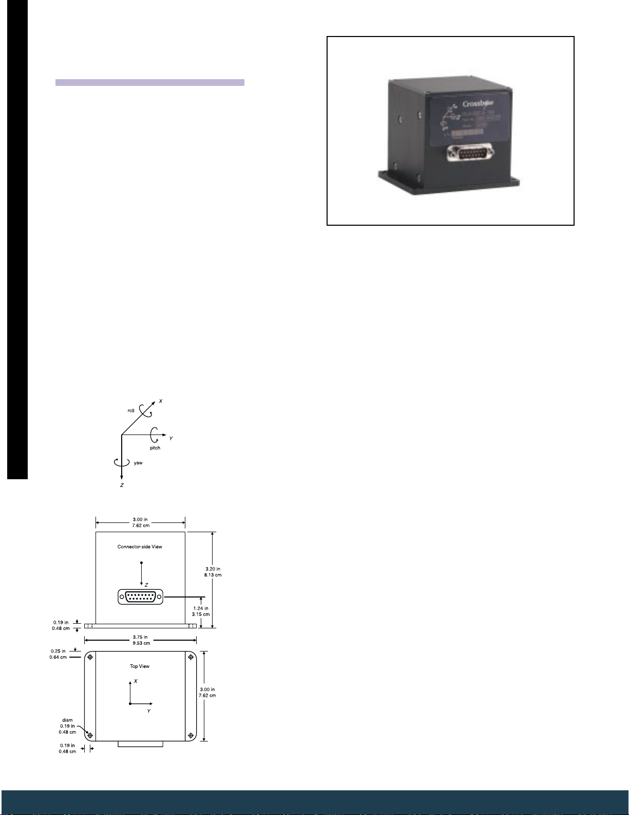
Physical
Size (in) 3.0 x 3.75 x 3.20 Includ. mounting flanges
Weight (lbs) < 1.3
Connector 15 pin sub-miniature “D” male
Notes
1
All DAC analog outputs are fully buffered and are designed to interface directly to data
acquisition equipment.
Specifications subject to change without notice
1/2
) < 2.25 Typical
1/2
) < 0.15
0 to 5.0 Pins 5, 6, 7
(cm) 7.62 x 9.53 x 8.13 Includ. mounting flanges
(kg) < 0.59
C
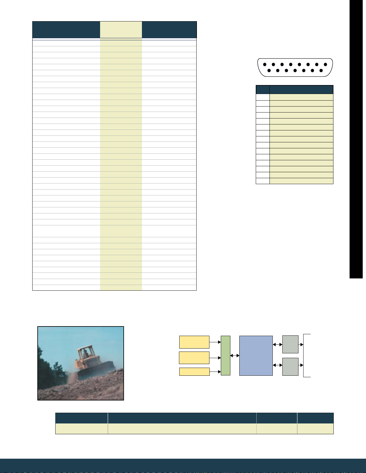
15 Pin "D" Connector Male Pinout
1 2 3 4 5 6 7 8
9 10 11 12 13 14 15
Pin Signal
1 RS-232 Transmit Data
2 RS-232 Receive Data
3 Input Power
4 Ground
5 X-axis Accel Voltage
6 Y-axis Accel Voltage
7 Z-axis Accel Voltage
8 X-axis Acceleration
9 Y-axis Acceleration
10 Z-axis Acceleration
11 NC – Factory Use Only
12 Roll Angle
13 Pitch Angle
14 Yaw-axis Angular Rate
15 NC – Factory Use Only
Notes
1 The accelerometer voltage outputs are taken
directly from the accelerometers without
compensation or scaling.
2 The compensated accelerometer analog
outputs are scaled to represent G. Outputs are
created by a D/A converter.
3 Roll and Pitch angle analog outputs are
scaled to represent degrees. Outputs are
created by a D/A converter.
4 The angular rate analog output is scaled to
represent degrees/second. The Output is
created by D/A converter.
3
Pin Diagram
1
1
1
2
2
2
3
4
▼
Tri-axial
Accelerometer
14-bit A/D
Yaw-Rate
Gyroscope
Temp Sensor
RGA Block Diagram
Ordering Information
Model Description Gyro (°/sec) Accel (g)
RGA300CA-100 Yaw Rate Gyro and Accelerometers ±100 ± 2
CALL FACTORY FOR OTHER CONFIGURATIONS
phone: 408.965.3300 ▼ fax: 408.324.4840 ▼ e-mail: info@xbow.com ▼ web: www.xbow.com
RS-232
CPU + EEPROM
Digital
Output
Calibration
Algorithm
Document Part Number: 6103-0036-01
12-bit
DAC
Analog
Output
Roll and
inertial systems
Pitch Angle
XYZ
Acceleration
Yaw
Angular Rate
61
▼
 Loading...