

Cross SwitchUPS SU1000, SwitchUPS SU1400XR, SwitchUPS SU1400, SwitchUPS SU1800, SwitchUPS SU2200 User Manual
...Page 1
Uninterruptible Power System
SU1000,1400,1400XR,1800,
2200/SU RM Series
User’s Manual
www.switchups.com
Part Number 2001-0110 / Revised 01/2001
Page 2

Table of contents
1. Introduction
2. Safety precaution
3. Presentation
4. Installation
5. Operation
6. UPS monitoring
7. Battery cartridge replacement
8. Difficulty
9. Storing the UPS
10. Specifications.
Page2
Page 3

Important safety instructions!
Please read this manual!
Thank you for selecting this CROSS Uninterruptible Power System (UPS). It has
been designed for many years of reliable, maintenance free service. This manual
provides safety, installation and operating instructions that will help you derive the
fullest performance and service life that the UPS has to offer.
PLEASE SAVE THIS MANUAL! It includes important instructions for the safe
use of this UPS and for obtaining factory service should the proper operation of the
UPS come into question. Down the road, service or storage issues may arise and
require reference to this manual.
Please save or recycle the packaging materials!
The UPS’s shipping materials were designed with great care to provide protection
from transportation related damage. The shipping materials will become invaluable
to you in case the UPS must be returned to the factory for service (damages
sustained in transit when shipped from the user are not covered under warranty).
WARNING: Changes or modifications to this unit not expressly approved by the
party responsible for compliance could void the user’s authority to operate the
equipment.
Page3
Page 4
1. Introduction
Overview
This SwitchUPS is a high performance standby uninterruptible power system
(UPS) designed to provide clean, reliable AC power to computer loads and
electronic devices. When utility failure, low or high voltage intermittently, UPS
can feed your computer or electronic appliances without any interruption. It
can keep you away from brownouts, spikes, lightning and high frequency
interference. It can automatically save your computer data, protect your
software, even the hardware, to ensure your computers or precision equipment
work functionally and efficiently.
1.1 Operation principle
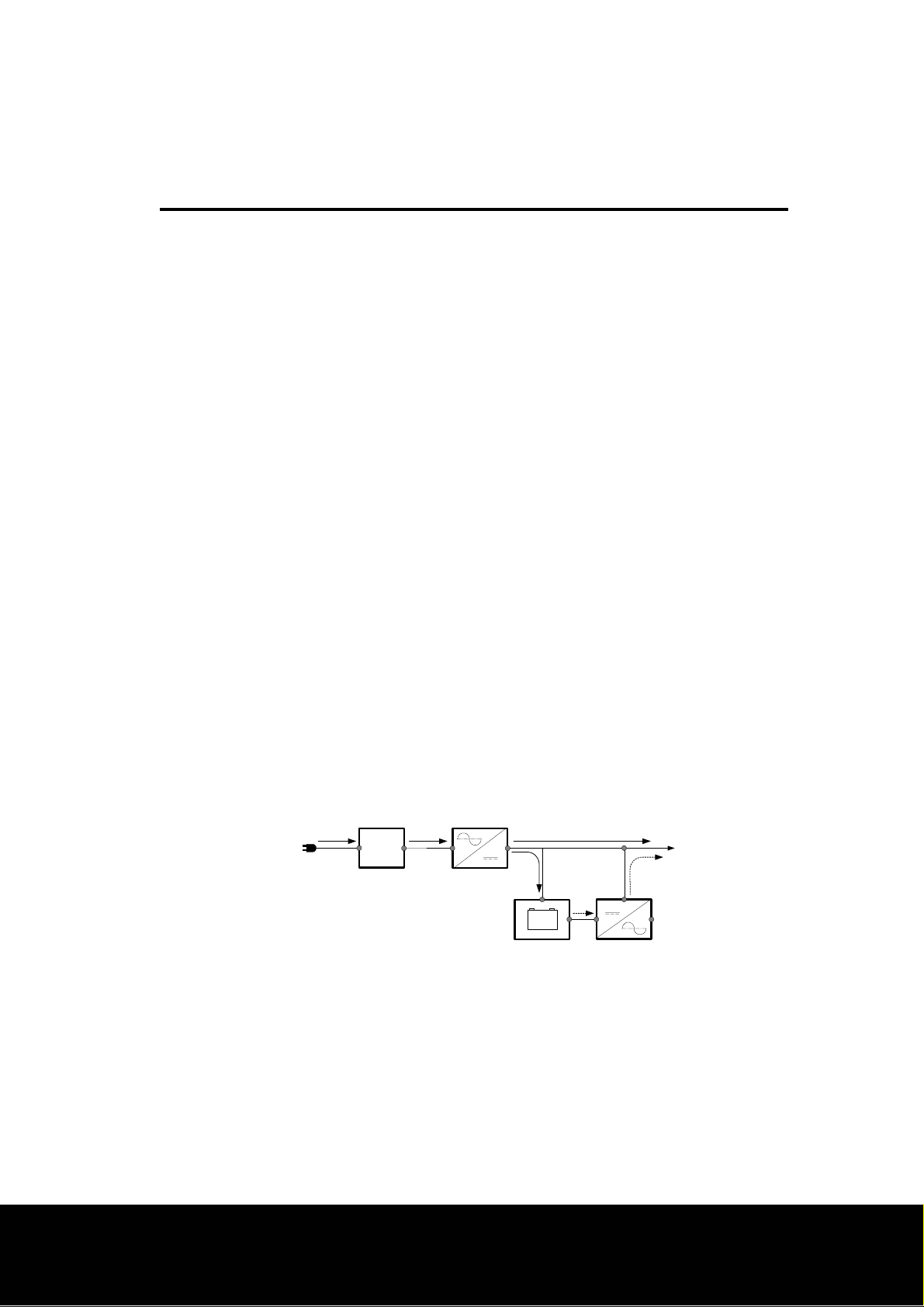
1.1.1 Utility normal: The UPS offers the pure and stable AC output power by
the synchronous voltage regulator and EMI/RFI filter. A unique mode of
operation, named AutoBoost, serves to regulate the load voltage by
compensating for brownouts or sags, and AutoTrim allows continuous
on-line operation during over line voltage conditions. This is
accomplished without the need to draw power from the UPS’s battery.
In anticipation of utility failure, the UPS continuously monitors the line
and prepares the inverter frequency for synchronous transfer of the
load.
AC INPUT
EMI/RFI
FILTER
CONVERTER
AC
DC
LOAD
+-
BATTERY
INNVERTER
Page4
Page 5
1. Introduction
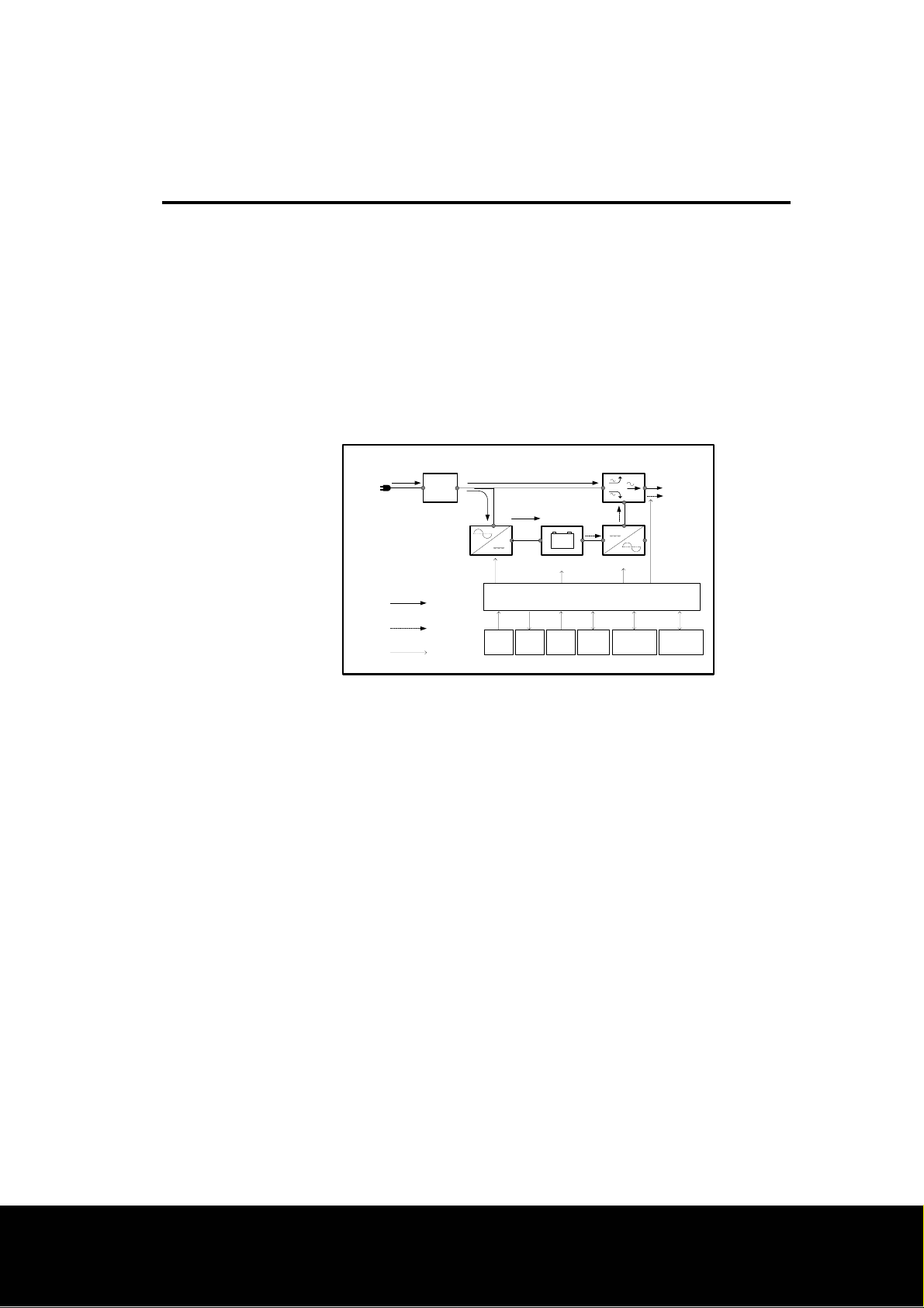
1.1.2 Utility failure or abnormal: Upon occurrence of utility voltage failure
such as a blackout, severe brownout or an over-voltage condition, the
UPS transfers the load to power derived from battery. Transfer to the
“On-battery” mode of operation takes place typically within 2
milliseconds. The inverter’s output voltage wave shape is a low
distortion sine wave. Resynchronization and retransfer to on-line
operation is automatic upon recovery of the line voltage to within
normal limits.
AC INPUT
1.2 Products features
1.2.1 AutoBoost/AutoTrim
AutoBoost/AutoTrim allows continuous on-line operation during
extended brownouts or low/high line voltage conditions. The UPS
compensates for the reduced/increased line voltage by
boosting/trimming the load voltage to a value 10% above the input.
Reliability is enhanced because the limited battery capacity is saved for
complete utility failures.
EMI/RFI
FILTER
CONVERTER
Line operation
Backup operation
Microprocessor soperation
Auto Boost
/Auto Trim
LOAD
AC
DC
Test
&Load
Button
+-
BATTERY
MICROPROCESSOR
Front
Volage
Start
Selector
Monitor &
Protection
LED
Display
INVERTER
RS-232
DATA
Communication
SNMP
Communication
1.3.2 Battery replacement indicators and test
The UPS provides both visual and audible Replace Battery indications.
The Indications are based on the result of an actual load test on the
battery. By exercising the UPS’s battery during a startup test, the UPS
is able to detect a weak battery before it is put into service. In
applications where the UPS is not turned off daily, or where the UPS is
purposely left operating unattended, the UPS automatically conducts this
self test.
Page5
Page 6

1. Introduction
1.3.3 Remote interfaces
The UPS provides a remote computer interface capable of full bidirectional RS-232 communications. When combined with UPS
monitoring software and a serially connected local PC, power quality
related events can be logged. UPSilon2000 offers all the features of
UPS monitoring and management software, plus the ability to control
orderly and unattended network or multi-user computer system
shutdown during an extended power outage. Also available for the UPS
is the SNMP (Simple Network Management Protocol) Adapter to provide
load type independent remote monitoring and management across
Ethernet or Token Ring based LANs or WANs capable of routing IP
messages. Using any standard Network Management System (NMS)
and the SNMP Adapter, the UPS becomes manageable through a single
familiar interface-from across your building to across the world.
UPSilon2000 software provides complete data protection for most
operating systems such Windows, Linux, Unix, Win NT, LAN manager.
This software is a background process that monitors the UPS through a
RS-232 serial port on the host.
1.3.4 Input and output frequency
The UPS allows any of input frequency, 50Hz or 60Hz. Via the UPS’s
microprocessor, the input frequency can be internally selected. Also
the UPS provides the pure and stable output frequency.
Page6
Page 7

2. Safety
2.1 Connect the UPS to a two-pole, three-wire grounding mains receptacle.
The receptacle must be connected to appropriate branch protection (fuse
or circuit breaker). Connection to any other type of receptacle may result
in a shock hazard and may violate local electrical codes.
2.2 To reduce the risk of electric shock, disconnect the UPS from the mains
before installing computer interface signal cable (when used). Reconnect
the power cord only after all signaling interconnections have been made.
2.3 Do not open the UPS cabinet without the instruction from the local service
center, or UPS will not be valid for warranty.
2.4 This UPS has an internal energy source (the battery) that cannot be deenergized by the user. The output may be energized when the unit is not
connected to a mains supply.
2.5 To properly de-energize the UPS in an emergency, move the rear panel I/O
switch to O (off) position and disconnect the power cord from the mains.
2.6 Avoid installing the UPS in locations where there is water or excessive
humidity.
2.7 Do not allow water or any foreign object to get inside the UPS. Do not put
objects containing liquid on or near the unit.
2.8 To reduce the risk of overheating the UPS, avoid exposing the unit to the
direct rays of the sun. Avoid installing the unit near heat emitting
appliances such as a room heater or stove.
Page7
Page 8
3. Presentation
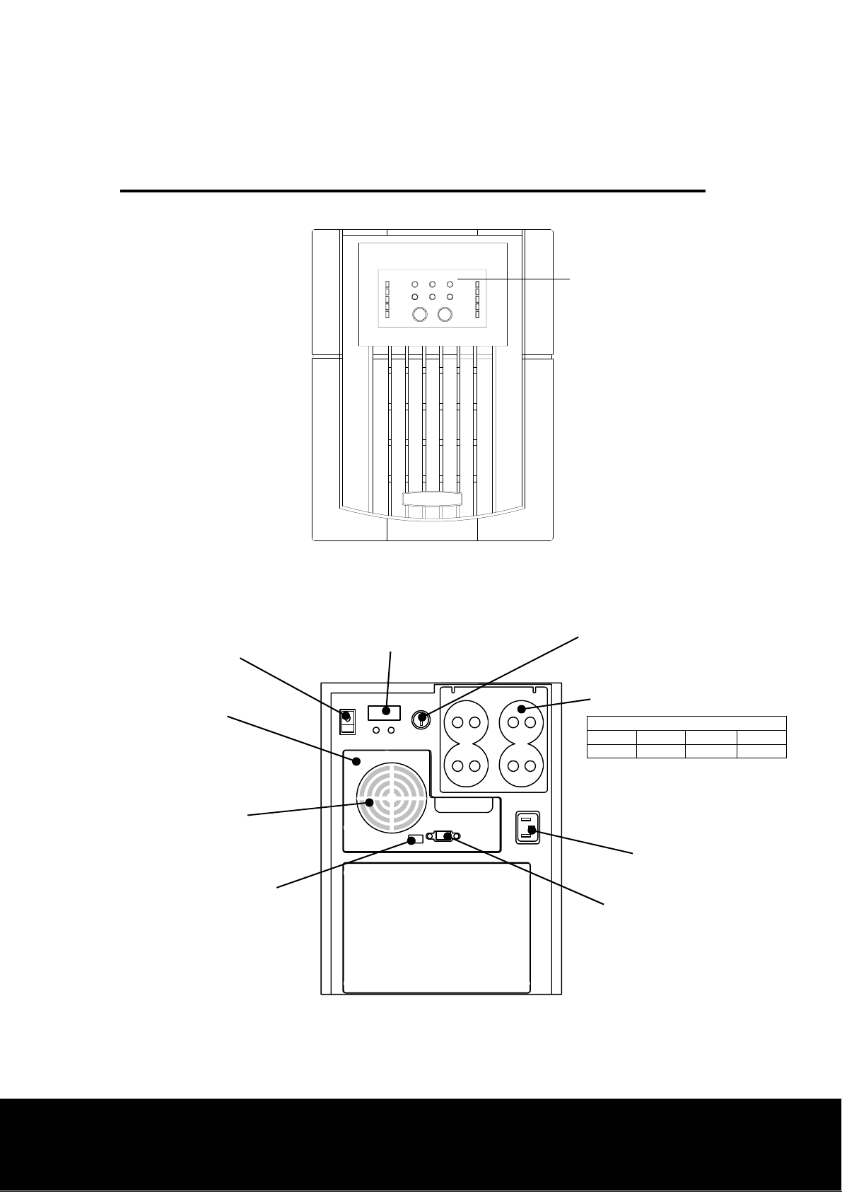
3.1 Front view I (Display features shall cover all models of SwitchUPS.)
3.2 Rear view I (for Models SU1400XR/SU1800/SU2200)
UPS Enable/On switch
Electronics enclosure
Extensional battery pack coupler
Display features
See section
5.1
Input protection fuse
Output couplers
Capacity of input protection fuse (250V of rating)
1kVA 1.4kVA 1.8&2.2kVA 3kVA
7Amps 10Amps 15Amps 20Amps
Ventilator
Inlet
Option switches
Computer interface port
Battery enclosure
Note : output couples are manufacthrer’s Standard, and it shall be changed according to customer’s requirements
Page8
Page 9
3. Presentation
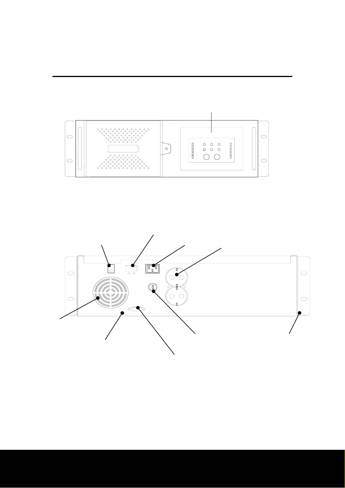
3.3 Front view II (19” Rack mount models)
Display features
See section
5.1
3.4 Rear view II
(for Models SURM1000/SURM1400/SU1400XR/SURM1800/SURM2200)
UPS Enable/On switch
Battery enclosure
Extensional battery pack coupler
Inlet Output couplers
Ventilator
Option switches
Input protection fuse
Computer interface port
Page9
Rack-mounting clamp
Page 10
3. Presentation
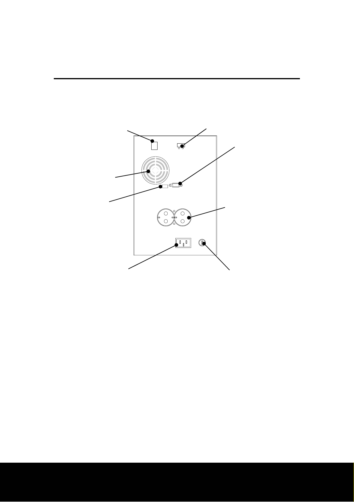
3.5 Rear view III (for Models SU1000/SU1400)
UPS Enable/On switch
Ventilator
Option switches
Inlet
Extensional battery pack coupler
Computer interface port
Output couplers
Input protection fuse
Page10
Page 11
4. Installation
Receiving inspection
4.1
Once the UPS has been removed from its shipping container, if should be
inspected for damage that may have occurred while in transit. Immediately
notify the carrier and place of purchase if any damage in found. The packing
materials are made from recyclable materials and should be saved for reuse or
disposed of properly.
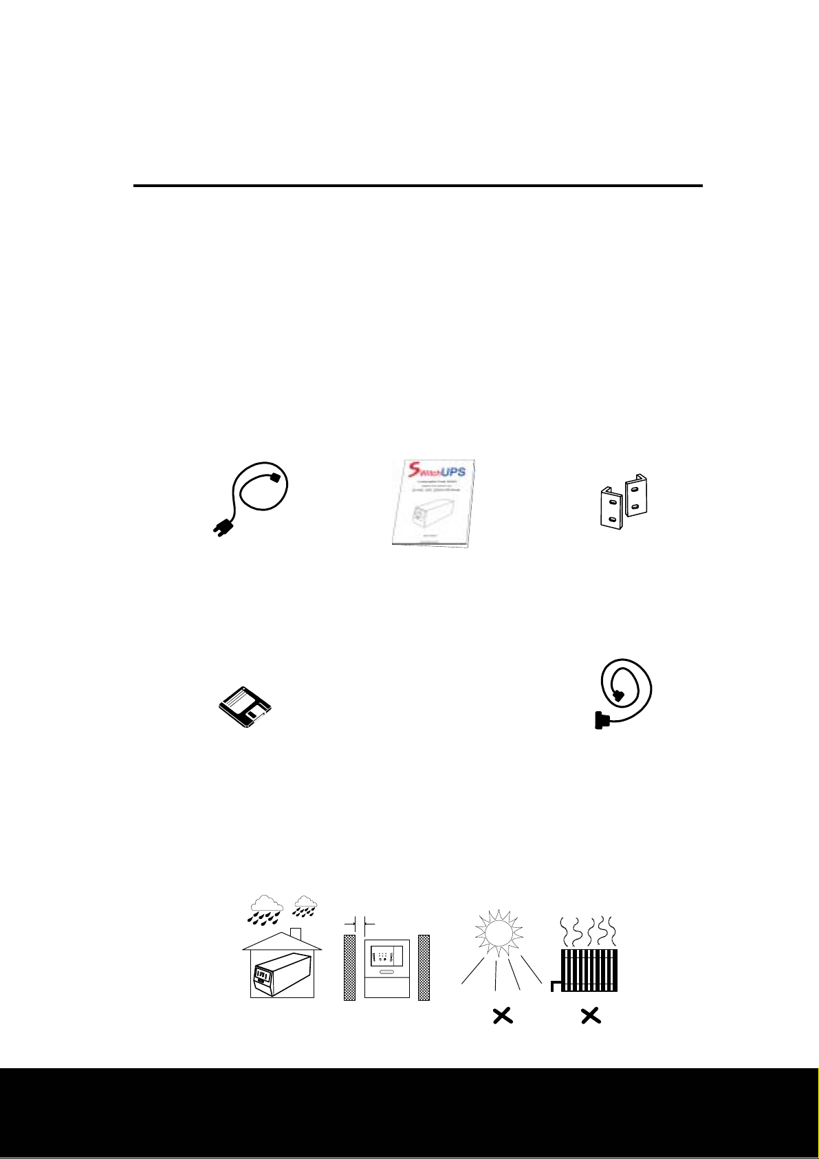
4.1 Checking accessories
4.1.1 Standard accessories
( Input power cord X 1pc )
4.1.2 Optional accessories
(UPS monitoring software CD or 3.5” floppy disk ) ( Computer interface cable )
( User’s manual X 1copy ) Rack-mounting clamp
(if you purchased Rack mount type)
4.2 Placement
The UPS may be installed in any protected environment. The location should
provide adequate airflow around the unit, in an atmosphere free from excessive
dust.
2.5 cm
Page11
Page 12
4. Installation
Note: Allow 2.5cm minimum clearance on all sides for proper ventilation.
Do not operate the UPS in an environment where the ambient temperature or
humidity is outside the limits given in the Specifications section of this manual.
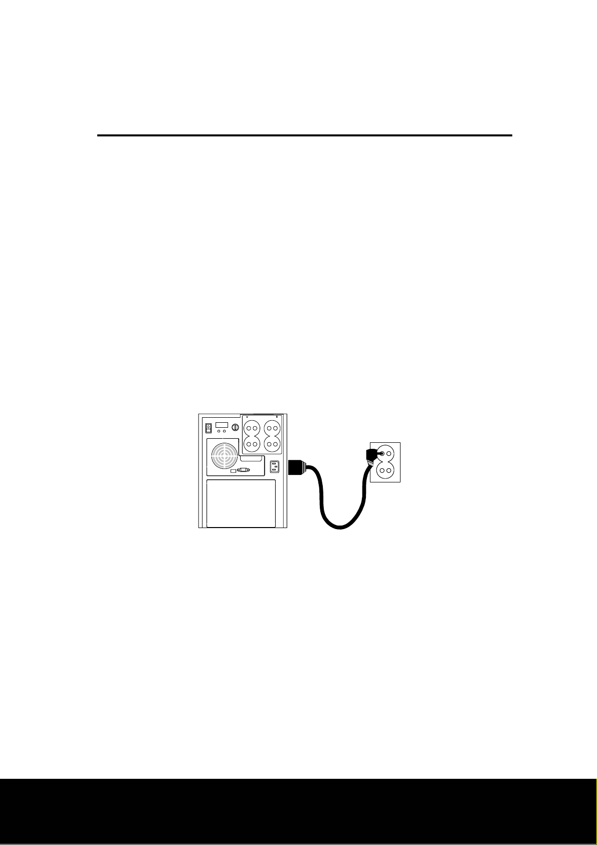
4.3 Connect UPS to service and switch on
Plug the UPS into a working wall outlet which of two-pole, three wire grounding
receptacle using by factory supplied input power cords.
SwitchUPS is compatible with all 200, 220 and 230Vac mains vo ltages. The UPS
may be configured to operate where 220Vac service is provided. When Option
switch 1 is set to the “ON” position, the UPS’s transfer and on-battery output
voltages are adjusted for proper operation on 200Vac service. Also if Option
switch 2 is set to the “ON” position, the UPS’s transfer and on-battery output
voltages are adjusted for proper operation on 230Vac service.
4.3.1 Connect extension battery pack – PowerCell GUARD only (Optional parts)
No need any tool to connect extension battery pack. Just mate the battery
pack coupler to the electronics enclosure.
PowerCell GUARD can provide over 2 times longer run time than standard
model.
Page12
Page 13
4. Installation
4.4 Plug loads into UPS
Plug all loads to be protected into the UPS. Do not exceed the UPS’s capacity as
given in section 9. Once switched ON, the UPS will monitor and display the
magnitude of the applied load.
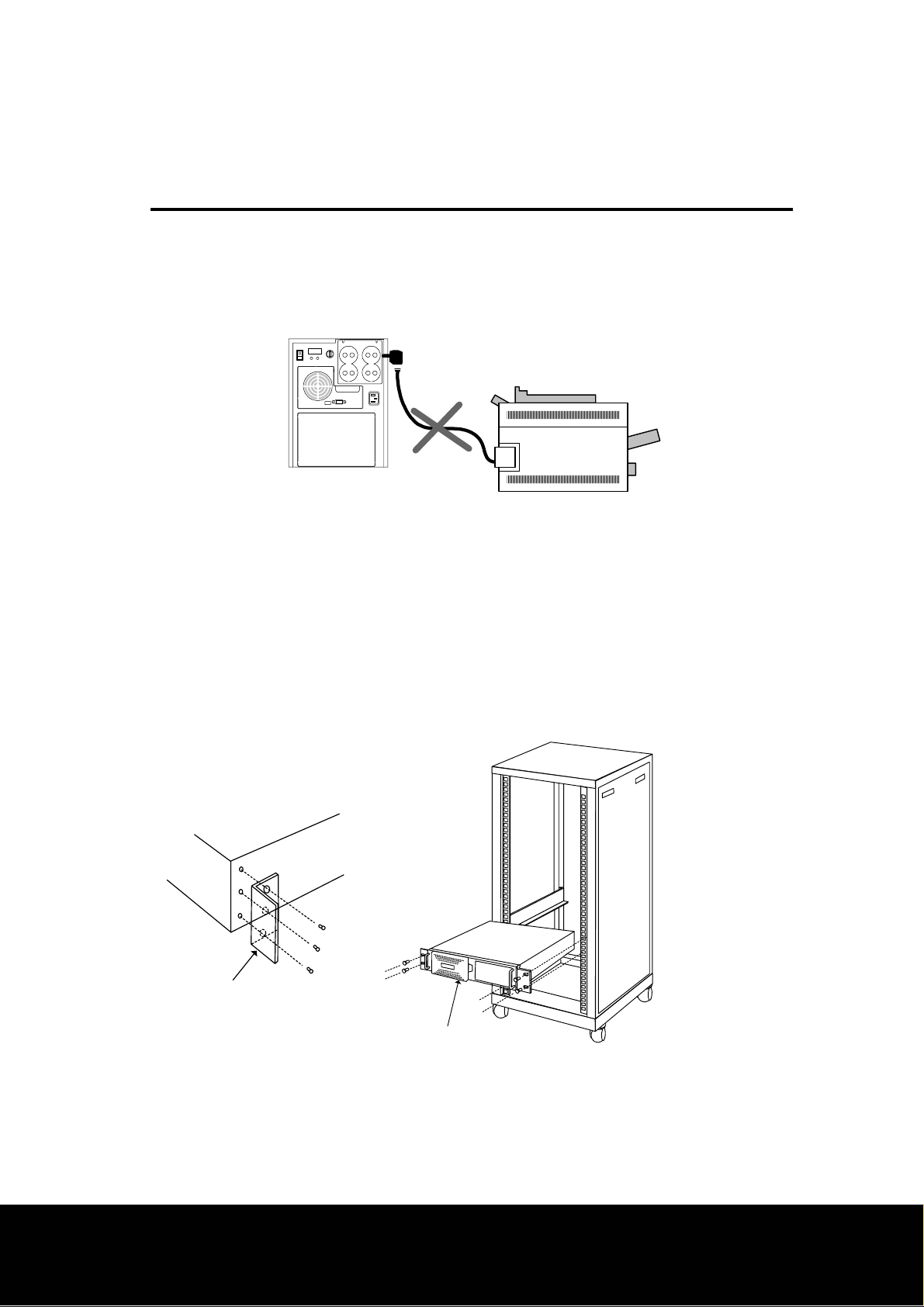
Note: Do not plug laser printers, refrigerators, electric stoves or hair dryer etc into
this UPS. These devices draw a considerable amount of power. These will
reduce the available backup time and in some cases will cause the UPS to signal an
overload.
4.5 Install Rack mount UPS (models SwitchUPS RM)
SwitchUPS Rackmount are designed for 19 inches width of rack structure, and the
UPS’s height is 5.25 inches tall.
랙 고정 유니트
SU RM 1000~2200 Series
-Mate the Rack mount clamp to left and right side of the UPS enclosure.
-Fasten Rack mount clamp to lock in place using by screwdriver.
-Put the UPS into the rack, and fasten Rack mount clamp to lock in place.
Page13
Page 14
5. Operation
5.1 Display features
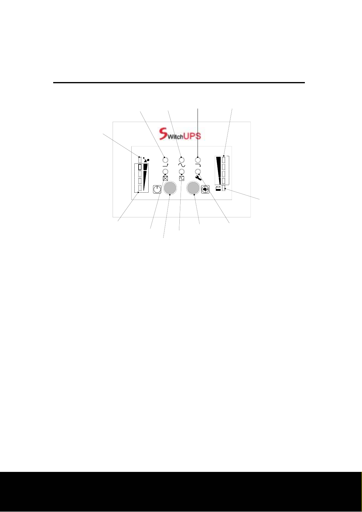
AutoBoost indicator On-line indicator AutoTrim indicator Battery bar graph
Over load indicator
Load Level Batt. Level
TEST
Low battery indicator
Output power bar graph
Replace battery indicator
On battery indicator
On/Test pushbutton
Alarm disable pushbutton
Trouble indicator
5.1.1 Enable/Switch on the UPS
The Enable/On switch is used to control activation of the UPS and to energize the load
when Option switch 5 is set to the ON (I) position (See section 5.6). When shipped, this
switch is in the “OFF” position to prevent accidental activation of the UPS. The
batteries will not appreciably discharge if this switch is left “ON”(See section
3.2/3.4/3.5).
Note: The UPS may be configured to operate on Auto starting mode (Option switch 5 is
set to the ON (I) position. See section 5.6.
Once powered, all indicators will blink, and the UPS will initiate a battery test.
During the test, the UPS will operate the load from power derived from the
battery. This test function ensures that the UPS is working properly and that
its battery does not require replacement. The test will take about 15 seconds,
and the test is completed when the On Line indicator illuminate. After battery
test, the UPS’s battery charger will be started if required.
In the event the batteries are too weak to support the load during the test,
trouble indicator will be illuminated, and the UPS emits continuous beeps. The
UPS’s battery charger will operate when the utility voltage is over 154Vac
Page14
Page 15

5. Operation
while trouble indicator is illuminated. Th e on-line indicat or will be illuminated
when the batteries is charged as sufficient as to activate control of the UPS.
The trouble warning cannot be muted.
If you need to do battery test where mains are not available, set Option switch
4 to the ON (I) position. See section 5.6.
Note: If the red Load indicator is illuminated, the UPS is overloaded. Unplug
equipment that does not require backing up, such as a printer, and restart the UPS.
Allow the UPS to charge its battery for at least 8 hours before use. The UPS
recharges its battery whenever the utility voltage is normal and UPS Enable/On
switch is ON. While the UPS was shipped from the factory with the batteries in a
fully charged state, the batteries may lose some charge during shipping and storage.
You may use the UPS immediately without charging, but the Low Battery indicator
may illuminate and the UPS may have reduced backup time until the battery has had
an opportunity to charge.
Note: When moved the switch to the OFF (O) position, this control will de-energize the
UPS and all protected loads.
TEST
will initiate a battery test when Option switch 5 is set to the ON (I) position. This will
force the UPS to operate on-battery for a brief time during which the UPS determines
the strength of the battery. In the event the batteries are too weak to support the load
during the test, the UPS will immediately return to on-line operation.
When Option switch 4 is set to the ON (I) position, pressing the button will switch on
the UPS when the mains are not available.
Once the UPS conn ected to the mains and Op tion switches 4 and 5 are set to the OFF
(O) position, pressing the button will switch on the UPS.
5.1.2 On/Test pushbutton: Once the UPS is energized, pressing the button
Page15
Page 16

5. Operation
5.1.3 AutoBoost: Illumination of AutoBoost indicator means that the AutoBoost
circuitry has been engaged to compensate for unacceptably low line voltage. The UPS
is capable of operating in this mode continuously without draining charge from the
battery.
5.1.4 On Line indicator: Illumination of the On Line indicator means that the load is
being supplied conditioned power derived from the utility service. The indicator outs
during the blackout, low voltage or over voltage conditions.
5.1.5 AutoTrim: Illumination of AutoTrim indicator means that the AutoTrim
circuitry has been engaged to compensate for unacceptably over line voltage.
5.1.6 Battery capacity bar graph: The battery capacity bar graph continuously displays
the state of battery charge. Where power quality is fair, the UPS will be able to
maintain the battery at 100% of rated capacity. In the event of an extended utility
failure, the capacity shown will decrease at a rate dependent on the load drawn from
the UPS. Large computer loads will cause the battery capacity indication to fall at a
faster rate.
5.1.7 Low battery indicator: When low battery conditions are reached, the bottom-
most bar will illuminate.
5.1.8 Trouble indicator: In the event of an short-circuit of output cable, weak
battery, over/low output voltage or miscellaneous trouble of UPS, the trouble indicator
will illuminate and emits constant tone.
5.1.9 Alarm disable pushbutton: This button may be pressed to silence the
trouble audible warning which of caused by utility failure only.
5.1.10 On battery indicator: Illumination of the On Battery indicator means that
load has been transferred to power derived from the UPS’s battery and that utility
voltage is not within normal limits.
Page16
Page 17
5. Operation
TEST
5.1.11 Test pushbutton: Once the UPS is energized, pressing the button will
initiate a battery test. This will force the UPS to operate on-battery for a brief time
during which the UPS determines the strength of the battery. In the event the
batteries are too weak to support the load during the test, the UPS will immediately
return to on-line operation.
5.1.12 Replace Battery indicator: Illumination of the Replace Battery indicator and
emits “chirps” occasionally means that the automatic battery test has found that the
battery is weak and requires replacement. The indicator is extinguished following a
successful battery test.
5.1.13 Output power & line voltage bar graph: The output power bar graph displays the
power drawn from the UPS as a percentage of the UPS’s full rated capacity.
5.1.14 Over load indicator: If the UPS becomes overloaded, the overload
indicator will illuminate and the UPS will sound an alarm.
5.2 Battery capacity bar graph
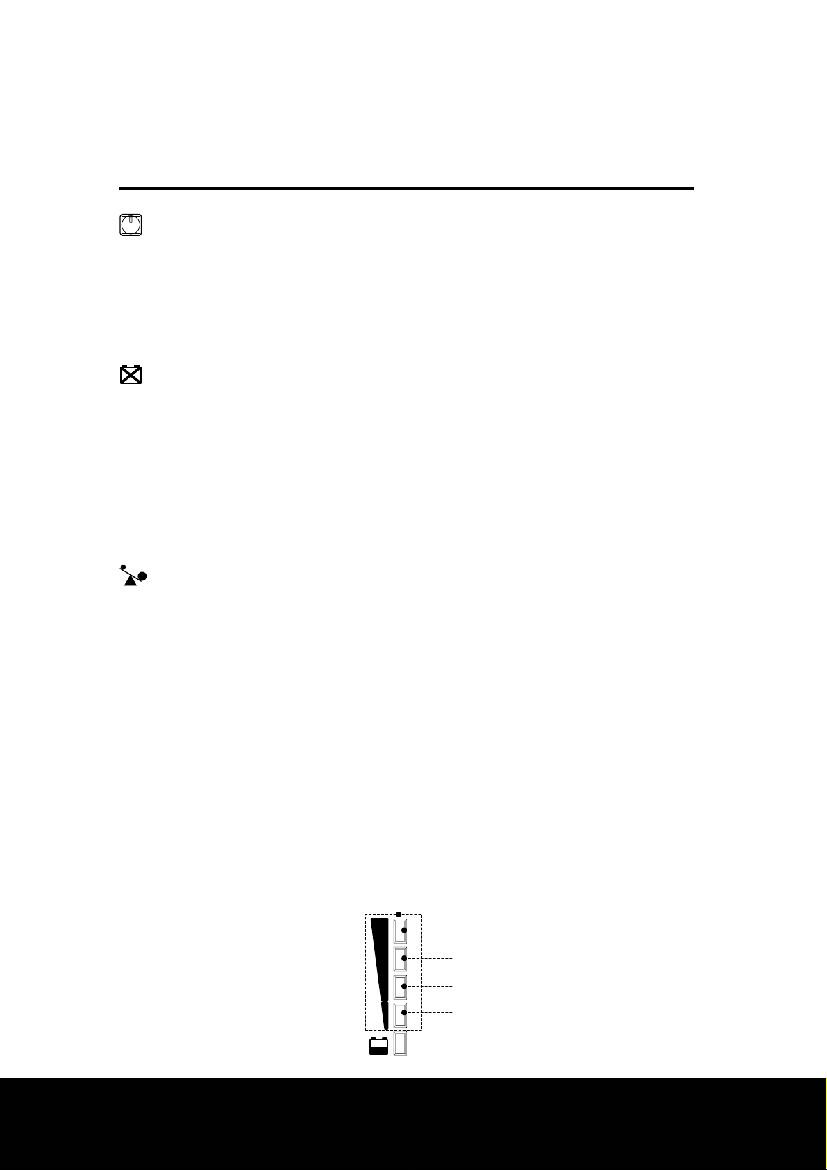
The battery capacity bar graph continuously displays the state of battery charge. In
the above example, the display shows that 75% of rated battery capacity is available.
Where power quality is fair, the UPS will be able to maintain the battery at 100%of
rated capacity. In the event of an extended utility failure, the capacity shown will
decrease at a rate dependent on the load drawn from the UPS. Large computer loads
will cause the battery capacity indication to fall at a faster rate. When low battery
conditions are reached, the bottom-most bar will illuminate, and the UPS emits a short
beeps every 1 seconds.
Battery capacity bar graph
100%
75%
50%
25%
Batt. Level
Page17
Page 18
5. Operation
5.3 Output power bar graph
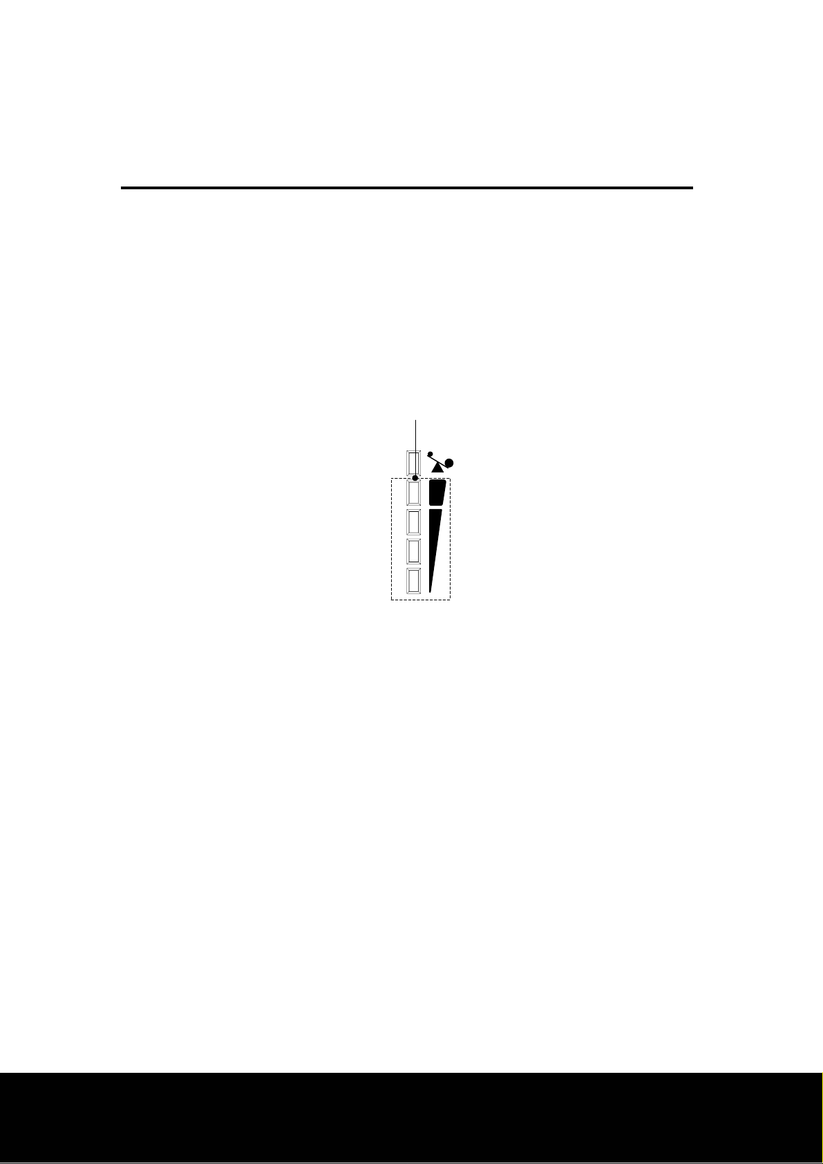
The output power bar graph displays the power drawn from the UPS as a percentage of
the UPS’s full rated capacity. This example shows that the load equipment is drawing
between 75% and 100% of the rated capacity. When the UPS is loa ded such that four
bar illuminated, thoroughly test your complete system to be sure the UPS will not
become overloaded. A thorough test includes running backup tape drives, disk drives,
etc. If the UPS becomes overloaded, the overload bar will illuminate and the UPS will
sound an alarm.
Output bar graph
Load Level
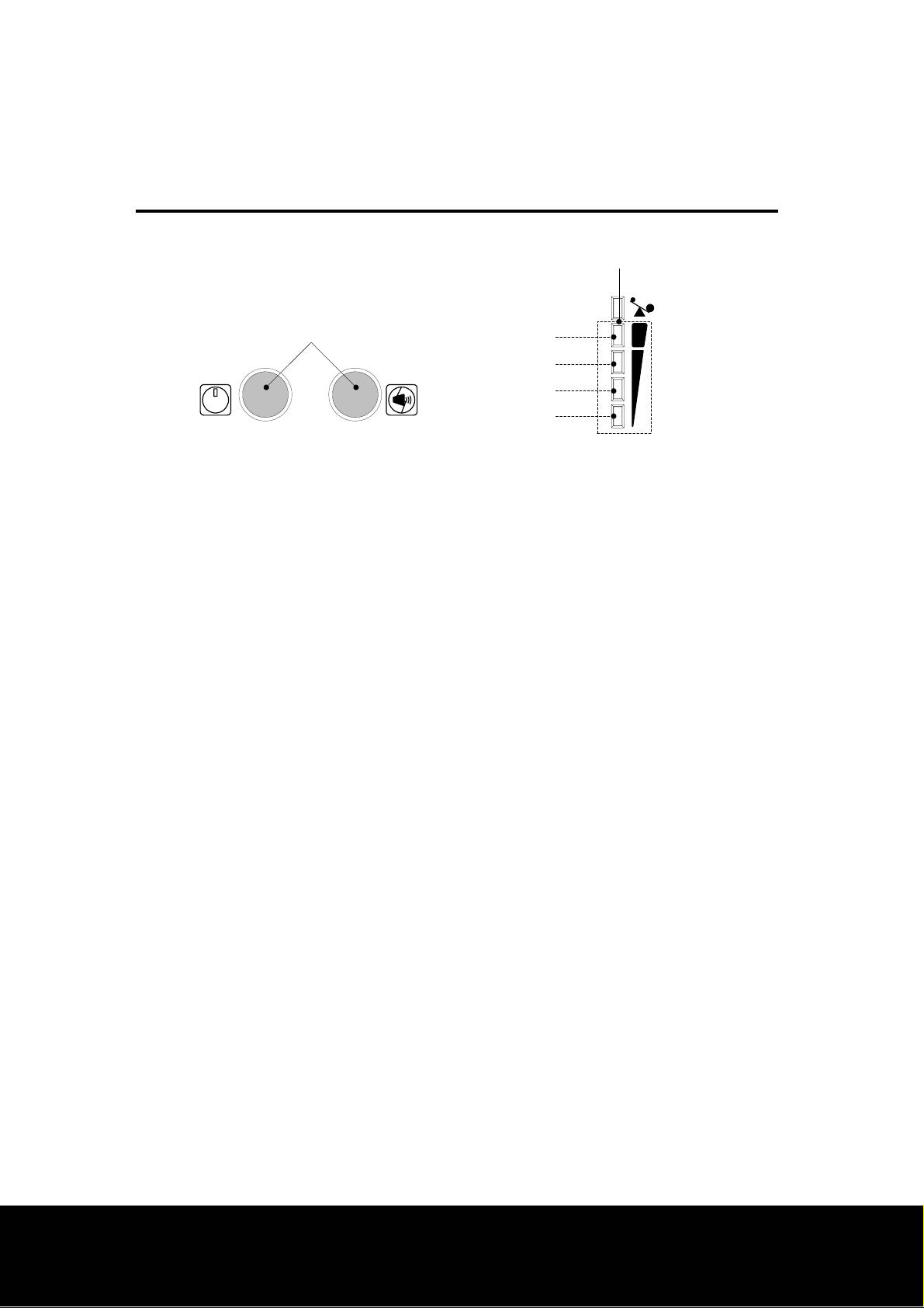
5.4 Line voltage bar graph
The line voltage bar graph displays the UPS’s input voltage in discrete steps. Line
voltage is disp layed when the On/Test and Alarm disa ble pushbutton are pressed and
held. The example above shows that the UPS’s input line voltage is between 210 and
229 Vac. If no bars are illuminated, an d the UPS is plugged into a known work ing wall
outlet, the line voltage is extremely low. Low input voltage could be a result of an
overloaded branch circuit, a misadjusted service pole transformer or intentional local
service brownout. The UPS will compensate for this problem by boosting the load
voltage supplied to your computer equipment. If all four bars are illuminated, the line
voltage is high and should be checked by a qualified electrician. The UPS will
compensate for this problem by trimming the load voltage supplied to your computer
equipment.
Page18
Page 19
5. Operation
TEST
☜
275~290Vac
210~229Vac
180~209Vac
150~179Vac
Output bar graph
Load Level
5.5 Audible alarm
The UPS contains a beeper that emits sound through the ventilation opening. Events
that cause the beeper to sound are listed below.
5.5.1 On-battery operation
The UPS emits a short beeps every 4 seconds following failure of the utility. The
audible alarm is silenced when the Alarm disable pushbutton is pressed.
5.5.2 Low battery
During an extended utility failure, the UPS will eventually emit a short beeps every 1
second before shut down due to battery capacity exhaustion. The low battery warning
cannot be muted.
5.5.3 Overload
The UPS will emit a short beeps every 1 second when overloaded. The alarm will
sound until the overload is removed. W hen the overload is appli ed while on-battery,
the alarm will be silenced after 18 seconds which of upon the UPS shut downed if the
overload does not removed immediately.
5.5.4 Replace battery
In the event the UPS’s battery fails a battery test, the UPS will emit “chirps” every 3
seconds until the battery replaced or the UPS Power I/O switch is switched off.
Page19
Page 20
5. Operation
5.5.5 Miscellaneous UPS’s trouble
In the event of miscellaneous UPS’s trouble such as short-circuit of output cable,
over/low output voltage or other miscellaneous trouble, the trouble indicator will
illuminate and emits a short beeps every 1 second. If Trouble indicator is illuminated,
the UPS should be checked and tested by an electrician who is qualified by the
manufacturer.
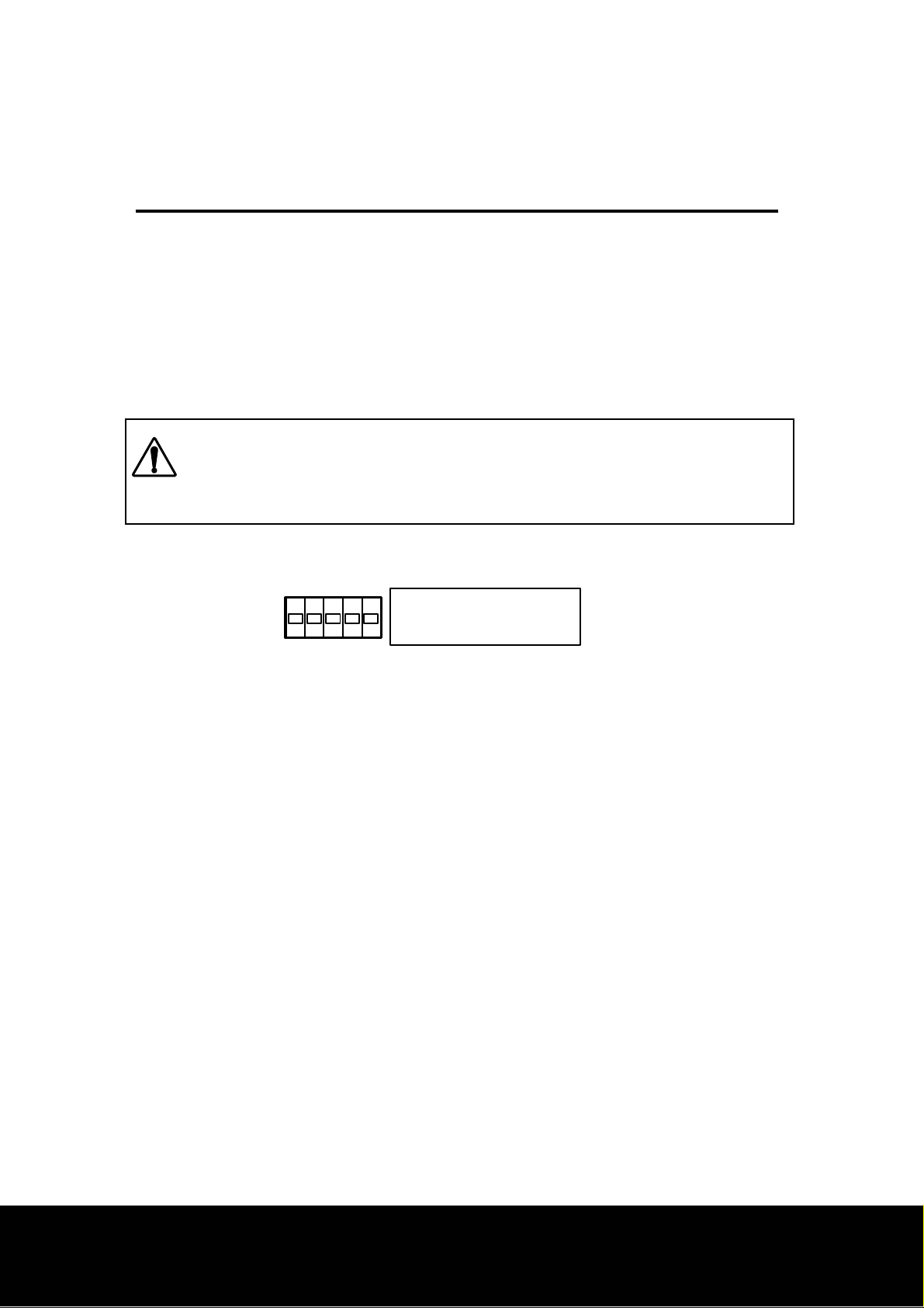
5.6 Option switches
Note: Option switches may not be effect during activation of the UPS.
The Enable/On switch is moved to the OFF (O) position for to set Option
switches.
Option switch
DIP SWITCH
12345
1 : 200Vac
2 : 220Vac
3 : 230Vac
4 : DC START
5 : AUTO START
5.6.1 Option switches 1, 2 & 3
The UPS’s factory set on-battery output voltage and input voltage limits for on-line and
AutoBoost/AutoTrim operations are appropriate for use in regions where the nominal
line voltage is 200 to 230Vac. When the Option switches 1, 2 or 3 is set to the ON (I)
position, the UPS’s transfer and on-battery output voltage are adjusted for proper
operation on its service voltage.
5.6.2 Option switch 4
The Option switch 4 is used to do battery test and energize the loads when the mains
are not available. Once the Enable/On switch moved to the ON (I) position, pressing
the On/Test pushbutton will initiate a battery test and energized the loads.
5.6.3 Option switch 5
Switch on of the Option switch 5 means that the UPS is on automatic starting mode that
the UPS’s control is activated and the loads energized automatically when Enable/On
switch move to the ON (I) position and the UPS is plugged into a working outlet.
Page20
Page 21
5. Operation
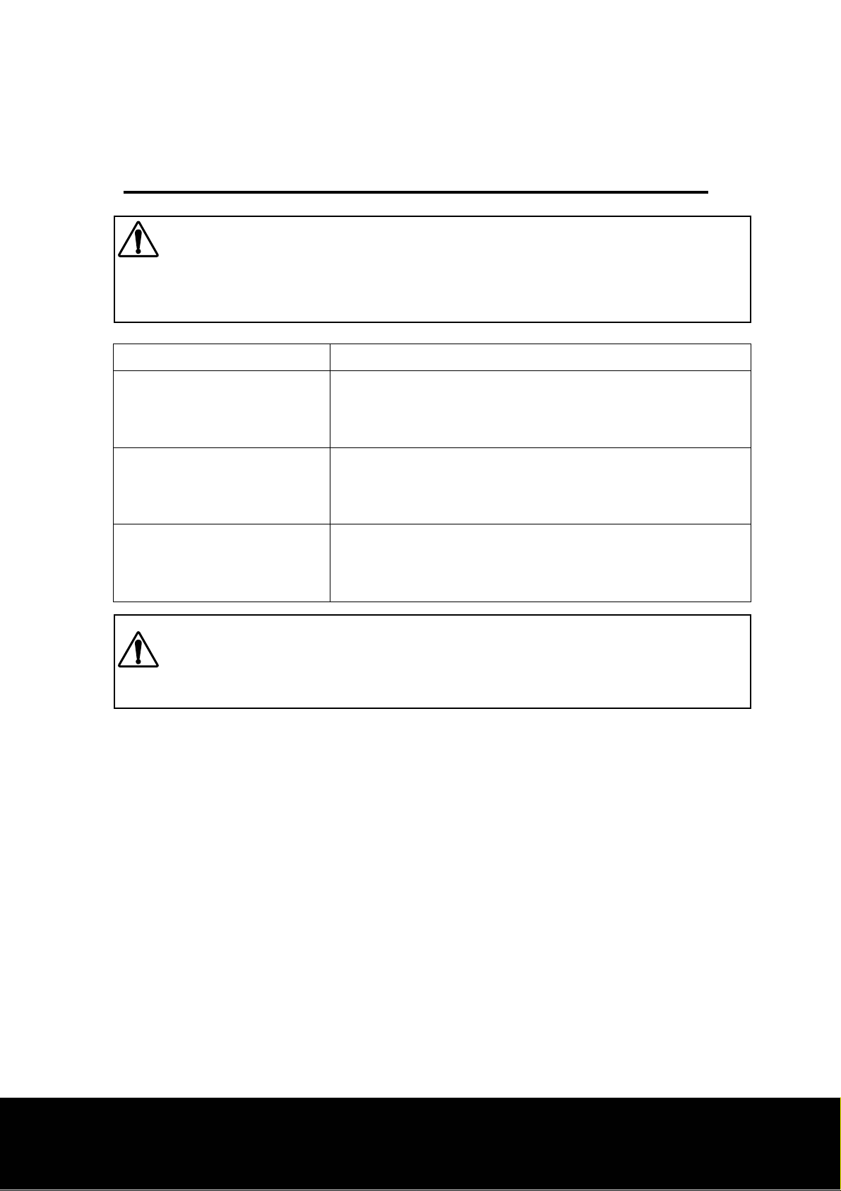
Note: To initiate a battery test and to energize the loads, On/Test pushbutton is
pressed when Option switch 4 & 5 is moved to the OFF (O) position and the UPS
is plugged in the normal utility. In the event the UPS does not connected to the
mains, the UPS does not be activated and the loads will not be energized.
Option switch status How to switch on the UPS
(Automatic starting mode)
Option switch 4 “OFF”
Option switch 5 “ON”
(DC starting mode)
Option switch 4 “ON”
Option switch 5 “OFF”
(Auto & DC starting off mode)
Option switch 4 “OFF”
Option switch 5 “OFF”
1. Plug the UPS into a working outlet
2. Move the Enable/On switch to the ON (I) position
1. Move the Enable/On switch to the ON (I) position
2. Press On/Test pushbutton
1. Plug the UPS into a working outlet
2. Move the Enable/On switch to the ON (I) position
3. Press On/Test pushbutton
Note: Do not set both Option switches of 4 and 5 to the “ON” position on the
same time. Also, only one switch is set to the ON (I) position among the Option
switch 1, 2 & 3.
5.7 Extended capabilities
The following sections briefly describe the UPS’s extended capabilities. These
advanced functions are accessed by a computer running optional UPSilon2000 UPS
monitoring software. See the UPS monitoring software literature for more information
on the application of these functions.
5.7.1 Status reporting
● Operating status – When queried, the UPS reports its current operating status.
Reported modes includes on-line, on-battery, Auto Boost, Auto Trim, overloaded output,
low battery, shut down and internal fault.
● Test results – When queried, the UPS reports the stored results of the last automatic
or manually initiated battery test. The user may also test the operation of the UPS’s
visual and audible indicator.
Page21
Page 22

5. Operation
5.7.2 Monitoring
● Battery capacity – When on-battery, the UPS continuously monitors the remaining
battery capacity as a percentage of the fully charged condition.
● Line voltage and frequency – The UPS continuously monitors the rms line voltage
and the line frequency. Transients lasting less than 0.5 seconds are not reported.
This information can be logged using UPS monitoring software.
● Minimum and maximum line voltage – The minimum and maximum line voltage is
recorded to provide a snapshot of power quality over a user specified interval.
Transients lasting less than 0.5 seconds are not recorded.
● Output power – The UPS continuously monitors the power consumed by the load.
The value given is a percentage of the full load rating of the UPS. This information can
be logged using UPS monitoring software.
● Output voltage, internal temperature, battery voltage, battery capacity – The UPS
continuously monitors the rms output voltage, internal temperature in degrees Celsius,
battery voltage, and the remaining battery capacity as a percentage of the fully charged
condition. This information is valuable for troubleshooting purposes.
5.7.3 Power management
● Shut down – While operating on-battery, the UPS may be directed to shut down
following a user set delay. Controlled shut down of the UPS conserves battery
capacity and exten ds battery l ife because th e UPS is not all owed to run until all battery
capacity is exhausted.
● Shut down with delayed restart – The UPS may be directed to shut down in any
mode following a user set delay, then restart after another user set delay.
● Turn off – The UPS may be directed to turn off immediately or following a user
settable delay.
Page22
Page 23

6. UPS Monitoring
6.1 Overview
A UPS system alone provides excellent protection from brief power problems.
However, during an extended power outage an unattended computer system will
eventually shut down due to battery capacity exhaustion. To prevent data corruption
when the UPS shuts down, the computer must be informed by the UPS of impending
shut down and take appropriate file-saving measures. This important function is called
“UPS monitoring.” The UPS’s computer interface port is the means by which your UPS
communicates with a computer system.
Some computer operating systems have built-in UPS monitoring. These systems
require various hardware interfaces. Interface kits for all operating systems that
support UPS monitoring are available from your dealer. In addition, your dealer also
offers UPSilon2000 software which enhances such built-in UPS monitoring.
6.2 Interface Kits
A series of interface kits is available for operating systems that provide UPS monitoring.
Each interface kit includes the special interface cable required to convert status signals
from the UPS into signals which individual operating systems recognize. Each kit
includes all necessary installation instructions.
6.3 UPSilon2000
UPSilon2000 software provides complete data protection for most operating systems.
This Software is a background process that monitors the UPS through a RS-232 serial
port on the host. UPSilon2000 offers user notification of impen ding shut down, power
event logging, auto-restart upon power return and UPS battery conservation features.
For selected operating systems, UPSilon2000 offers sophisticated power diagnostic and
network power management features. These include interactive battery testing;
scheduled server shut downs, re-boots and battery testing; detailed power quality
logging and a remote, real time, graphical power status display showing UPS loading
and battery conditions.
Page23
Page 24
6. UPS Monitoring
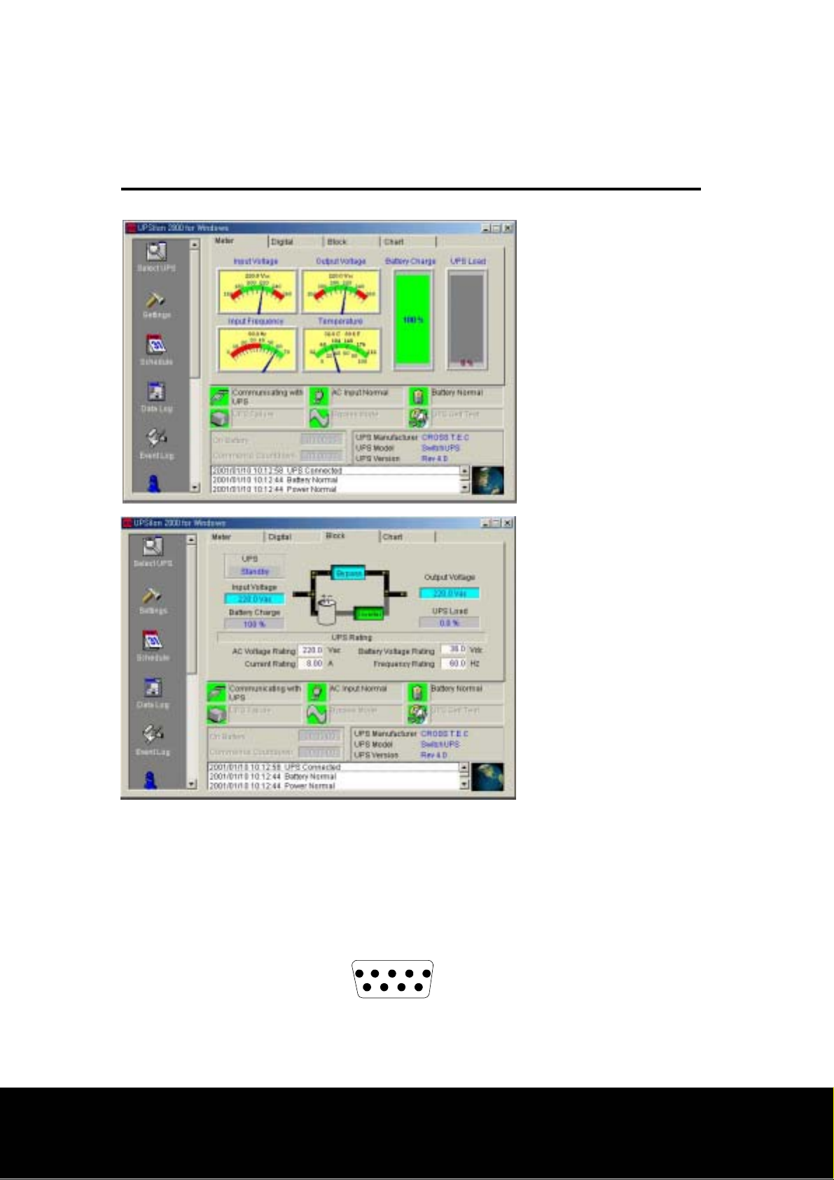
6.4 Computer interface port
The computer interface port is diagramed below for your reference. Those with
technical abilities wishing to use this port in a special application should be aware of the
following limitations and capabilities of the interface.
Pin 2: RXD(Receive Data)
Pin 3: TXD(Transmit Data)
12345
Pin 4: GND(Ground)
6789
Page24
Page 25
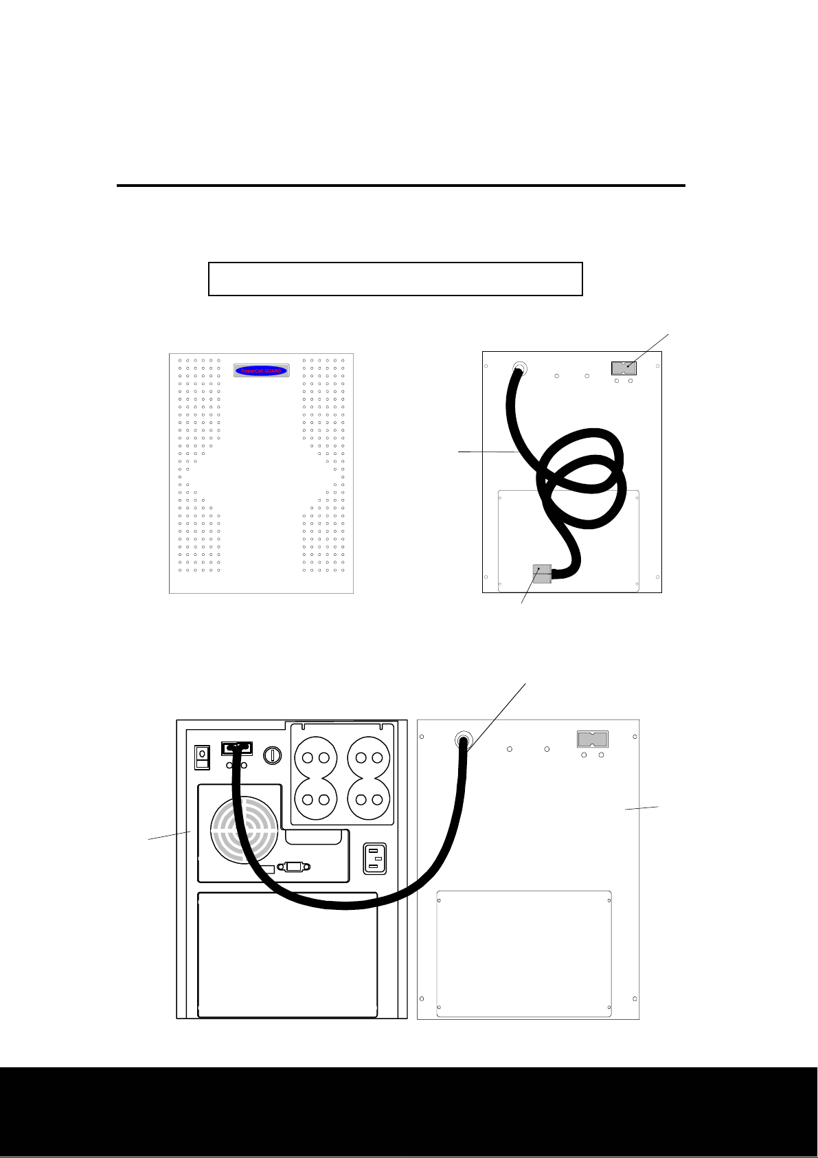
7. Battery cartridge replacement
7.1 Models SU1000XR, SU1400XR, SU1800 & SU2200
Extended battery pack - PowerCell GUARD
PowerCell GUARD
Battery pack cable
Coupler to the UPS PACK
((FRONT VIEW))
Battery pack cable
PG2406 배터리 연결선
Extension battery
pack plate for 2nd
additional
Battery pack
((REAR VIEW))
UPS
Battery pack
Page25
Page 26
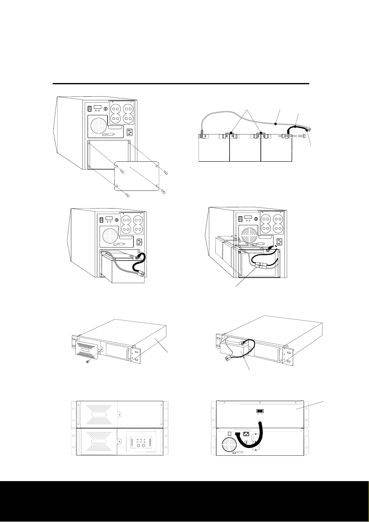
7. Battery cartridge replacement
Connection bus bar
Battery coupler
-
+
7.2 Models SwitchUPS Rackmount(SU1000/1400/’1800/2200/3000)
19” Rack mount UPS
24AH or 7AH
Extension
battery pack
Page26
Page 27

8. Difficulty
This UPS contains potentially hazardous voltages. Do not attempt to disassemble the
unit. The unit contains no user serviceable parts. Repairs are performed only by
trained service personnel.
This UPS uses batteries. The batteries will eventually become too weak to provide
rated autonomous operation. Due to the potential health and environmental hazards
posed by the batteries, they may be replaced only at factory authorized Service Centers.
To obtain battery replacement or repair service, please call the Customer Service
telephone number written on the cover of this manual for information on the Service
Center nearest you.
The batteries used by this UPS are recyclable. Proper disposal of the batteries is
required. The batteries contain lead and pose a hazard to the environment and human
health if not disposed of properly. Please refer to local codes for proper disposal
requirements or return the unit to a factory authorized Service Center for battery
replacement or disposal.
Battery replacement should be performed or supervised by personnel familiar with the
danger of batteries and the required precautions. Keep unauthorized personnel away
from batteries. When replacing batteries, use the same number and type of sealed lead
acid batteries as were originally contained in your UPS.
CAUTION – Do not dispose of batteries in a fire. The batteries may explode.
CAUTION – Do not open or mutilate batterie s. They contain an electrolyte, which is
toxic and harmful to the skin and eyes.
CAUTION – A battery can present a risk of electrical shock and high short circuit
current. When replacing batteries, wrist watches and jewelry such as rings should be
removed. Use tools with insulated handles.
Page27
Page 28

8. Difficulty
8.1 Troubleshooting chart
PROBLEM POSSIBLE CAUSE ACTION TO TAKE
UPS will not turn on 1. UPS Enable switch is in the
OFF position or front panel
switch not pressed.
2. UPS’s input protection fuse
is melted.
3. Very low utility voltage or
dead outlet.
UPS operates onbattery even though
normal line voltage is
thought to exist.
1. Very high, low or badly
distorted line voltage
2. UPS’s input protection fuse
is melted.
1. Turn on the rear panel
UPS Enable switch or
press front panel switch
to power UPS and
loads.
2. Replace fuse by new
one which of suitable
capacity.
3. Check outlet with a
table lamp. If very
dim, have utility voltage
checked by an
electrician.
1. Test the input voltage
with UPS’s line voltage
bar graph.
2. Replace fuse by new
Trouble indicator is
illuminated and UPS
emits constant tome.
Over load indicator is
illuminated and UPS
emits a short “beeps”
UPS does not provide 1. UPS’s battery is weak due 1. The UPS’s batteries
1. Internal UPS fault
2. Short circuit of loads
UPS is overloaded. Unplug non-critical
one which of suitable
capacity – see below.
1. Do not attempt to use
UPS. Turn off UPS and
have it serviced
immediately.
2. Turn off UPS and turn
on the rear panel UPS
Enable switch after
short circuit is
recovered.
equipment such as printers.
Page28
Page 29

expected back up time. to recent utility outage or
require recharging
Low battery light is
illuminated and on-line
light is extinguished.
Replace battery light is
wear.
2. UPS is overloaded.
UPS is shut down and batte ry
is discharged due to extended
power failure.
Weak battery Allow the batteries to
following an extended
outage. The batteries
will wear faster when
put into service often
and when operating at
elevated temperatures.
2. Check load using UPS’s
output power bar
graph-see section 5.1.
Unplug non-critical
equipment such as
printers.
UPS will return to normal
operation when power is
restored and battery has
charged sufficiently.
illuminated and UPS
emits “chirps”
Capacity of input protection fus e (250Volts of rating)
1kVA: 7Amps
1.4kVA: 10Amps
1.8kVA: 15Amps
2.2kVA: 15Amps
3kVA: 20Amps
recharge for at least 8
hours. If the problem
persists after recharging,
the batteries should be
replaced.
8.2 Battery replacement check
You can expect to receive 2 to 4 years of service life from the UPS’s batteries when
installed in a cool, dry location. Battery life is shortened when operated in an
environment where the ambient temperature is normally above 30℃ (86℉).
Page29
Page 30

8. Difficulty
The UPS automatically performs a battery test upon start up. Th is test actually loads
the battery for a brief time and will detect a weak battery before it is put into service
during a power failure. If the battery is too weak to support the load during this test,
the UPS will illuminate the Trouble indicator and emits continuous beeps. Even in this
case the UPS’s battery charger will operate if utility voltage is over 154Vac if trou ble
indicator is illuminated.
Note: The minimum charging voltage is –20% of nominal input voltage.
The UPS will illuminate the Replace Battery indicator when it is detected that the
batteries can no longer sustain sufficient charge. This means that the UPS would b e
unable to provide power for longer than half the normal interval during an extended
utility failure.
If the UPS illuminates the Replace Battery indicator, perform the following procedures
to be sure that the batteries need replacing.
8.2.1 Use the UPS’s Line voltage bar graph to check that the utility voltage is within a
normal range. The UPS will charge the batteries at a slower rate when operated from
very low input voltage.
8.2.2 Allow the UPS to charge the batteries for at least 8 hours following an extended
utility failure.
8.2.3 Recheck the UPS’s batteries by conducting a battery test. Press the On/Test
pushbutton to initiate the battery test.
8.2.4 If the Replace Battery indicator does not illuminate following the battery test, the
batteries do not require replacement. Extended storage without recharge, or
successive power outages can causes false indications.
8.2.5 If the Replace Battery is illuminated following the battery test, the batteries are
worn and need to be replaced.
Page30
Page 31

8. Difficulty
8.2.6 Call the Customer Service phone number given on the cover of this manual to
obtain information about battery replacement service or battery replacement kits.
Note: Please see the battery cautions at the beginning of this section.
8.3 Obtaining Service
The troubleshooting chart in section 8.1 covers most of the difficulties that a user may
encounter under conditions other than a failure of the UPS itself. For problems not
covered in the chart, the procedures outlined below should be followed.
If your UPS should require service:
◆ See the troubleshooting chart and eliminate the obvious.
◆ Note your UPS models, serial number and date of purchase. Contact the Customer
Service Department or local distributor at the phone number given on the cover of this
booklet.
◆ Be prepared to provide a description of the problem. A technician will help you
solve the problem over the phone if possible, or will give you a Return Material
Authorization Number (RMA#)
◆ If the UPS is within the warranty period, repairs will be performed free charge. If it
is not within the warranty period, there will be a charge for repair.
◆ Pack the UPS in its original packaging. If you no longer have the original shipping
materials, ask the technician about obtaining a new set. It is very important that you
pack the UPS properly to avoid damage in transit. Never use styrofoam beads for
packaging the UPS because it will settle through beads and become damaged.
Damages sustained in transit are not covered under warranty. Enclose a letter in the
package with your name, RMA#, address, copy of sales receipt, description of trouble,
phone number and check (if necessary).
◆ Mark your RMA# on the outside of the package. The factory cannot accept any
package without this marking.
◆ Return your UPS via insured, prepaid carrier to the address on the rear of this
booklet.
Page31
Page 32

9. Storing the UPS
9.1 Storage conditions
The UPS should be covered and stored upright in a cool dry location. The UPS
should be stored with its battery in a fully charged state. That is, the indicated
battery capacity should be 100% before the UPS is switched off for storage.
Disconnect accessories or cables connected at the computer interface port as such
devices may unnecessarily drain battery charge.
9.2 Extended storage
To achieve expected run time following extended storage, the UPS should be
allowed to refresh its batteries every 6 months in environments where the ambient
temperature is –15℃ to +30℃. For extended storage in environments where the
ambient temperature is +30℃ to +45℃, the UPS should be allowed to refresh its
batteries every 3 months.
Page32
Page 33

10. Spe c ifica t io n s
Power Capacity(KVA)
1000(950w)
1400va (1120w)
Topology Synthetic power On-line UPS
Isolation transformer Provides a galvanic isolation while operating the inverter operating
Recharge time(normal) 8 hours
Extended Battery Option Yes(PowerCell Guard)
Typical transfer time with load 2msec(Synthetic power On-line UPS)
1800va
(1440w)
2200va
(1540w)
3000va
(2520w)RM
Input Specification
Nominal input voltage and Frequency range
1 phase 200/220/230(user’s require)Voltage ±20% / Frequency 50/60 HZ ±5%
Output Specification
Nominal output voltage 1 phase 200/22/230 Dip switch selectable
Output voltage regulation
(Auto Boost & Auto Trim)
Output voltage waveform Sine wave
Load crest factor supported(c.f) Up to 5 : 1
Power factor tolerance Loads with 0.5 to 1.0 power factor
Normal 10% / On line 3%
Efficiency inverter at full load >95%
Audible noise(front 1.5m away) 43 Dba
Overload capacity Up to 110% for 10 seconds then transfer to inverter
Internal power distribution unit(PDU) 2 and 4 plugs
Feature
Runtime(Battery)Expandability Yes(PowerCell Guard)
User serviceable (SNMP Service) Quick SNMP & OTERS Win95/Win98)
Indicators, Interface & control
LED Indicators
Power cord Yes
Intelligent serial interface
(O/S management protocol)SNMP
Load level(25-100%), Battery level(25-100%, Auto Boost & Auto Trim, Inverter,
Battery abnormal, Alarm, Input voltage level(5 grade)
Yes(Quick SNMP & Power Mon II & SmartMon & Others GUI Protocol)
Others
DC Characteristics 27 – 39V
Battery type Lead-acid maintenance free & user’s optional
Page33
Page 34

Individual voltage & current monitoring Self diagnostic, replace battery warning indicator
Method of replacement Hand plug compatible & hot swappable
Dimension
(SU 1000/1400/1400XR/1800/2200)
Dimension
(SURM1000/1400/1800/2200/300)
Weight SU 1000/1400(14KG)
Extension battery (Power CELL Guard)
On site service Optional
SU 1000/1400
(H*W*D)310*240*460
(H*W*D)135*433(483)*510(540)
1800/SU2200/SURM1800/SURM2200(38kg)
PG2406(H*W*D)310*240*580 Weight(53kg)
PG2406RM(H*W*D)135*433(483)*510(540) Weight(54.2kg)
SU1400XR/1800/2200
(H*W*D)310*240*550
SU1400XR(SURM XR 1400)/SU
Page34
 Loading...