

Page 1

FP3000 RAID
USER'S MANUAL
1
CROSS T.E.C www.crossups.com
USER'S
MANUAL
Frontier power
-3000
U
NINTERRUPTIBLE
P
OWER
S
YSTEM
CROSS T.E.C Co., Ltd.
Page 2

FP3000 RAID
USER'S MANUAL
2
CROSS T.E.C www.crossups.com
CONTENTS
1. INTRODUCTION
2. SYSTEM DESCRIPTION
2.1. Foreword
2.2. Composition & Function
2.3. Operation
2.4. Electrical Characteristics
3. DELIVERY AND INSTALLATION
3.1. Delivery
3.2. Installation
4. OPERATION PROCEDURE
4.1. Preoperational Requirement
4.2. Preparations
4.3. Operational Procedure
4.4. Ending Operation Procedure
4.5. Emergency Operation
5. MAINTENANCE
AND SERVICES
5.1. Maintenance & Service
5.2. Handling
5.3. Display Panel Reading
5.4. Battery Maintenance
5.5. Operational Record
5.6. Inspection of Overall Operation of System
5.7. Status & Alarm Indication
5.8. Troubleshooting
6. LIMITED WARRANTY
Page 3

FP3000 RAID
USER'S MANUAL
3
CROSS T.E.C www.crossups.com
1. INTRODUCTION
First of all, we wish to thank each of you whom purchases our premier UPS F3000
RAID of CROSS TEC
The name of Frontier was originated from the key words of our company motto, which
is
"We, each and every member of
CROSS TEC(www.crossups.com)
shall head toward to
reach the top in the field as we try together with the original idea and the research
investment, firmly based on the concord and the sincerity of our good will"
. Those
keywords are Electricity, Sincerity, Concord, Original idea, Research investment,
and Top. As expressed in the name of FRONTIER itself, F3000 RAID
UPS system
serves as the guardian of all the sensitive power equipment including computers &
telecommunication systems and computerized instruments, and as well as our
confident and widely known representative product.
The F3000 RAID
Uninterruptible Power System
of CROSS TEC. is a truly advanced 3-phase on-line
sine wave UPS which Utilizes new power electronic technology such as Pulse Width
Modulation by IGBT(Insulated Gate Bipolar Transistor), and is designed to offer
high efficiency, low operational noise, compact size, better reliability, and easy
access for maintenance and service to our most valuable customer.
We put all together of our inspiration, intuition, energy, effort, and resources
in our premier F3000
-3000 Uninterruptible Power Supply System
.
2. SYSTEM DESCRIPTION
2.1. Foreword
This UPS system facilitates sine wave Pulse Width Modulation which
instantaneously controls the waveform to supply the uninterrupted constant
voltage and constant frequency balanced 3-phase AC power to the critical load
for smooth operation and fortified protection against unstable commercial
power failure such as outage, sag, surge, voltage transient, frequency change,
flicker, and etc.
Page 4

FP3000 RAID
USER'S MANUAL
4
CROSS T.E.C www.crossups.com
2.2. Composition and Functions
The F-
3000 system
is composed of numerous parts as follows,
- Input Transformer
- Rectifier & Battery Charger
- Inverter
- Output Transformer
- Static Switch
- Control Circuitry
- Digital Display
2.2.1. Input Transformer
This transformer is manufactured as H class dry type. The output voltage is
designed to correspond the input voltage of inverter and charging voltage of
battery, and the output current, to sufficiently match the sum of the
charging current and the rated current of inverter.
2.2.2. Rectifier & Battery Charger
This unit includes the thyristor module, heat dissipation board, and many
other components. It will convert input AC power to DC power, supply the
inverter, and simultaneously charge the battery with the best condition
possible.
Also, the filtering circuit composed of reactor and condenser, is employed
to filter out the ripple characteristics contained in the rectified DC power,
in order to yield the best possible DC power.
2.2.3. Inverter
This unit contains IGBT (Insulated Gate Bipolar Transistor) module, heat
dissipation board, rapid firing fuse for the semi-conductor protection and
other relevant component. The high frequency switching and the sine wave
Pulse Width Modulation, are utilized in this unit. The inverter will
revert the DC power obtained from rectifier to PWM AC output, and then the
AC filter will make it very similar to the balanced sinewave AC voltage to
supply the critical load.
Page 5

FP3000 RAID
USER'S MANUAL
5
CROSS T.E.C www.crossups.com
2.2.4. Output Transformer
The primary lead shall be connected to inverter and the secondary to output
in this isolation transformer. It is specially designed to contain the
reactance and partially serves as output filter.
Also, it minimizes the current harmonics, and maximizes efficiency. The
input and output voltage and frequency are synchronized by phase lock loop
oscillator. The synchronized transfer units are placed at the bypass line
and at the inverter section.
2.2.5. Static Switch
This unit operates as an automatic transfer device between inverter and
bypass feed. At the moment of detection of any abnormal operation in
inverter or over-load condition, the static switch will simultaneously
transfer the power supply to bypass feed (commercial power), not to
interrupt the load operation. When the inverter operation returns to
normal, the static switch will then retransfer supply line to inverter,
again without any interruption.
In order to avoid the possible rush current evolved from the phase difference,
this unit is constituted with only semi-conductors.
2.2.6. Control Circuitry
This unit consists of inverter control, alarming circuit, static switch
control, and etc. It is designed to operate though the internal unexpected
voltage transient intervenes. Its power comes from the battery by DC/DC
converter, and thus, power outage or start-up peak current would not affect
the control circuitry operation.
Page 6

FP3000 RAID
USER'S MANUAL
6
CROSS T.E.C www.crossups.com
2.2.7. Digital Display
This unit is placed in upper site of front panel for monitoring easiness and
displays the followings.
1) Measurement
- AC input voltage, current, & frequency measurement for each phase.
- AC output voltage, current, & frequency measurement for each
phase.
- Battery voltage measurement.
- Bypass input voltage, current, & frequency measurement for each
phase.
2) Operating condition
- Rectifier in operation ( RECT. ON )
- Rectifier out of operation ( RECT. OFF )
- Battery equalize charging ( EQU. )
- Battery float charging ( FLO. )
- Inverter in operation ( INV. ON )
- Inverter out of operation ( INV. OFF )
- Synchronized operation ( SYNC. )
- UPS in normal operation ( UPS NORMAL )
- Rectifier abnormal ( RECT. ALARM )
- DC line abnormal ( DC ALARM )
- Inverter operation abnormal ( INV. ALARM )
- Commercial bypass line abnormal ( BYPASS ALARM )
3) Control switches
- Circuit breakers ( CB1 - CB5 )
- Manual Transfer Button
- Lamp Test Button
- Reset Button
- Inverter ON & OFF Button
- Enable Button
Page 7

FP3000 RAID
USER'S MANUAL
7
CROSS T.E.C www.crossups.com
2.3. Operation
2.3.1. Normal
The rectifier and charger will get the AC commercial power and convert it to
DC, and then, send it to inverter for the reverse to AC and to battery
for charging. The filtered AC power from inverter will be supplied to the
load without interruption.
2.3.2. Power Outage
When commercial power fails, the battery starts to let out the reserved
DC power to inverter and it continues to feed the load during the power outage
for the defined time period.
2.3.3. Power Recovery
When the commercial power is recovered, the battery stops to feed and starts
to recharge. At the same time, the commercial power passes through the
normal routine.
2.3.4. Internal Failure & Over-load
The output voltage and frequency of inverter are synchronized with the
commercial power supply at all times. Thus, in case of internal
failure or over-load, the static switch transfers power to bypass feed and
the synchronized power is constantly fed to the load.
FOR THE ELECTRICAL CHARACTERISTICS
ON
PAGE 7.
INPUT VOLTAGE, OUTPUT VOLTAGE, BATTERY TYPE, CAPACITY ( BACK -UP TIME),
QUANTITY, SHALL BE SPECIFIED AT TIME OF PURCHASE.
* : When power outage, input power varies, or 0-100% load changes.
** : At rated input/output, and rated load.
*** : Control circuits, semi-conductors, condensers, and noise filters are excepted.
**** : When measured from 1.5m away, and 1.5m high.
Page 8
FP3000 RAID
USER'S MANUAL
8
CROSS T.E.C www.crossups.com
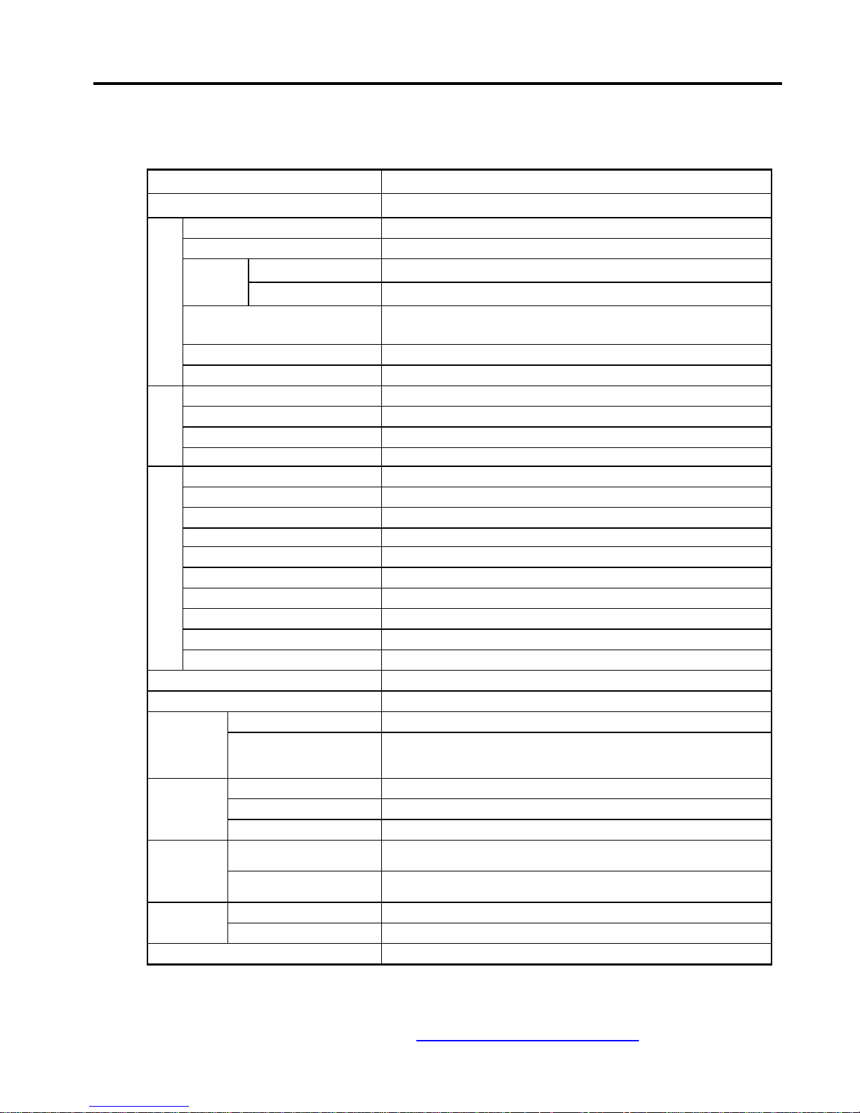
2.4. Electrical Characteristics
TYPE FP 3000 RAID
CAPACITY ( KVA )
COOLING MEYHOD Forced Air Cooling
OPERATION 100% Continuous
CONTROL 6 Phase Full-Bridge Controlling
RECT. &
CHRG.
SEMI-CONDUCTOR Thyristor
INVERTER CONTROL
Instantaneous Sine Wave PWM by IGBT
( Individual Phase Controlling )
ST/SW TRANSFER Automatic Synchronized Power Transfer by Semi-Conductor
G
E
N
E
R
A
L
TRANSFORMER H Class
No. OF PHASE 3 4 W
RATED VOLTAGE 380V
VOLTAGE VARIATION Rated Voltage 10%
I
N
P
U
T
RATED FREQUENCY 60 Hz 5%
No. OF PHASE 3 4 W
RATED VOLTAGE 380V
VOLTAGE STABILITY Within 2%
RATED FREQUENCY 60 Hz 0.5 Hz
* VOLTAGE REGULATION Within 5%
* RESPONSE TIME Less Than 20mS
VOLTAGE ADJUSTMENT Over 5%
WAVEFORM DISTORTION Less than THD 3% ( 100% Linear Load )
OVER-LOAD CAPACITY 120%, 10 Minutes
O
U
T
P
U
T
POWER FACTOR 0.8 Lag.
**** AUDIBLE NOISE 60 dBA
** TOTAL EFFICIENCY Over 87%
TRANSFER TIME Less than 4mS
STATIC
TRANSFER
TRANSFER CONDITION
o INVERTER FAILURE o OVER-LOAD
o DC LOW VOLTAGE o MANUAL TRANSFER
RATED VOLTAGE 240V
MAXIMUM VOLTAGE 270V
DC POWER
MINIMUM VOLTAGE 210V
*** WITHSTAND VOLTAGE AC 1500V, 60Hz for 1 Minute
INSUL- ATION
*** INSULATION RESISTANCE With DC 500V Megger, Over 5M
TRANSFORMERS Below 140 Degree
TEMP.
RISE
SEMI-CONDUCTORS Below 80 Degree
COLOR ( CASE COATING ) 5 Y 7/1 ( in Munsell No. )
Page 9

FP3000 RAID
USER'S MANUAL
9
CROSS T.E.C www.crossups.com
3. DELIVERY & INSTALLATION
3.1. Delivery
3.1.1. Advice
When delivering the UPS, the weight lifter of more capacity than the UPS's
weight is necessary and it should be applied to the bottom support of UPS
or the bottom part of the container. Also, the equipment should not be
neither shaken nor vibrated. If forced by nature, avoid the inclination of
the equipment more than 15 from the horizon.
3.1.2. Shipment inspection
- Inspect the delivered equipment in detail for any missing part or any
visible damage. If found any, notify CROSS T.E.Co. immediately.
- Never apply any sharp edged material or tool to the equipment.
- Avoid any form of physical shock to the equipment.It may cause the
malfunction of the system.
3.1.3. Storage Before Installation
Before installation, the UPS needs to be stored in a protected place from
humidity, dust and other damaging factors to the system performance.
3.2. INSTALLATION
3.2.1. Condition for installation
- Ambient Temperature : 0 C - 40 C
- Relative Humidity : Below 95% Non-Condensing
- Operating Altitude : Up to 1000m above sea level
Note
: This equipment is designed for indoor usage. Avoid installation where
exposed to rain, wind, direct sunlight, heat, and other damaging factor.
Page 10

FP3000 RAID
USER'S MANUAL
10
CROSS T.E.C www.crossups.com
3.2.2. Pre-installation Requirement
All the circuitry and the control panel are very delicate parts.
Hence, the careful handling is required. Sufficient space (about 20cm
distance) is necessary for the ventilation intake and outlet which are
placed in front and back of the equipment for air cooling.
3.2.3. Connection of Power
First of all, the size of the cable needs to be calculated according to the
necessary capacity of current, and then ensure the position where the cables
are connected. Make sure that all the circuit breakers are at "OFF"
position, and rearrange the input transformer wiring, as appropriate,
depending on AC input power. After completing the wiring of input
cables to the relevant terminal, battery cables need to be connected as
well with enough care and concern about the positive and the negative cables.
Note
: All the connections are to be made FIRM.
4. OPERATION PROCEDURE
4.1. Preoperational Requirement
4.1.1. Before starting the operation of the system, the operator (or whoever
wants to instruct the machine) is supposed to obtain enough
information and knowledge about start-up, shut-off, repair, routine
check, maintenance, and all other relevant system operation.
4.1.2. Make sure that cables are all at the appropriate places.
4.1.3. During the maintenance, if the UPS needs to be stopped, check and
ensure that the power is disconnected at least at the service required
section, in order to avoid the possible an electric shock.
4.2. Preparations
4.2.1. Check and verify that the input circuit breaker(CB1) and the output
circuit breaker(CB3) are in "OFF" position.
4.2.2. Check and verify that all the connectors and the circuit boards are at
Page 11

FP3000 RAID
USER'S MANUAL
11
CROSS T.E.C www.crossups.com
the right place, and the connections are firmly done.
4.3. Operational Procedure
Watch carefully for the front display panel throughout the procedure.
4.3.1. When all the circuit breakers are in "OFF" position, turn "ON" the
input circuit breaker(CB1).
( As the consequence of this action, RECT. ON, INV. OFF, INV.
ALARM, BYPASS ALARM LEDs will light "ON". )
* In order to clear any alarm status indication, PRESS "RESET" button of
selection switch section right side of front display panel.
( When any alarm condition is cleared, the UPS NORMAL LED will light "ON". )
4.3.2. Turn the battery circuit breaker (CB2) "ON".
( According to the amount of charging current detection, FLO. LED or
EQU. LED will light "ON". )
4.3.3. PRESS "ON" button and "ENABLE" button simultaneously for the
INVERTER operation.
( In several seconds, INVERTER will softly start its operation, and
the static switch will start to synchronize the inverter output
frequency and that of bypass commercial power. At this moment, the INV. OFF
LED will be "OFF", and the INV. ON and SYNC. LED will light "ON". )
4.3.4. Turn "ON" the bypass circuit breaker (CB4), so when the inverter
operation is interrupted, it can be transferred to the commercial
bypass line.
4.3.5. Turn on the output circuit breaker(CB3) in order to feed the load.
Note
: The EMERGENCY circuit breaker (CB5) shall be in "OFF" position during
the INVERTER operation.
Page 12

FP3000 RAID
USER'S MANUAL
12
CROSS T.E.C www.crossups.com
------
WARNING
---------------------------------------------------------
BEFORE turning on the output circuit breaker(CB3), operation of UPS MUST be done.
NOT CB3 then UPS. If done incorrectly, it may damage the load equipment and the
system itself.
-------------------------------------------------------------------------------
4.4. Ending Operation Procedure
4.4.1. Turn off any load fed from UPS, in order to separate the load and
UPS, and then turn the output circuit breaker (CB3) "OFF".
4.4.2. PRESS "OFF" button and "ENABLE" button switch together to halt
the INVERTER operation and to transfer to bypass mode.
4.4.3. Turn "OFF" the battery circuit breaker (CB2).
4.4.4. Turn "OFF" the bypass circuit breaker (CB4).
4.4.5. Turn "OFF" the input circuit breaker(CB1) to stop the system
operation.
4.5. Emergency Operation
If system must supply the power to the load, even though the inverter behaves in
abnormal way, PRESS "OFF" and "ENABLE" button switch to transfer to bypass feed
from inverter operation.
If worse gets worst and the bypass feed is impossible, TURN the EMERGENCY
circuit breaker (CB5) "ON" for the direct commercial power, and inform ASEA E&T
Co. for service as soon as possible.
Page 13

FP3000 RAID
USER'S MANUAL
13
CROSS T.E.C www.crossups.com
5. MAINTENANCE
&
SERVICE
5.1. Maintenance & Service
-------
WARNING
--------------------------------------------------------
There are no customer servicable units inside.
DO NOT open the cover and attempt to fix the unit. High voltage may remain when
the equipment is shut-off. The unauthorized service or attempt will void the
warranty and could cause the serious injury and the costly damage.
-------------------------------------------------------------------------------
The possible causes for the abnormal operation of UPS, are as follows;
5.1.1. Input power out of operational range.
5.1.2. Over-load out of operational range.
5.1.3. Ambient(surrounding) condition out of operational range.
5.1.4. Misuse.
5.1.5. Component failure.
5.1.6. etc.
5.2. Handling
The static UPS shall be treated and used as a delicate and sensitive equipment
like computer systems. At all times, adequate operational environment shall
be maintained such as ambient temperature of below 40 C, clean air,
sufficient ventilation, and so on.
5.3. Display Panel Reading
Periodically, checking and inspection of display panel reading is highly
recommended. It may offer the clues of future problem and may provide the
possible preparations of foreseen disaster.
Also, it is advised to read the display panel after any change was made to the
load, input, and operation of the system.
Page 14

FP3000 RAID
USER'S MANUAL
14
CROSS T.E.C www.crossups.com
Table #1 : SELECTION SWITCHES ( Right side of display ).
CATEGORY DESCRIPTION REMARK
INPUT To select the input power condition. White
BATT. To select the battery power condition. "
OUTPUT To select the output power condition. "
BYPASS To select the commercial power condition. "
V To check the volatge measurement. "
A To check the current measurement. "
F To check the frequency measurement. "
A To select the power condition of phase R. "
B To select the power condition of phase S. "
C To select the power condition of phase T. "
ON
To start the INVERTER operation.
( together with "ENABLE" button )
Green
OFF
To stop the INVERTER operation.
( together with "ENABLE" button )
Red
LAMP TEST To check the LED lamp operation. White
RESET To clear the alarm state. Blue-Green
MANUAL TRANSFER
To transfer to bypass mode manually.
( together with "ENABLE" button )
White
ENABLE
To start or stop the INVERTER operation.
( together with "ON", "OFF", or "MANUAL
TRANSFER" button )
"
Page 15

FP3000 RAID
USER'S MANUAL
15
CROSS T.E.C www.crossups.com
Table #2 : STATUS & SYSTEM OPERATION DIAGRAM.
5.4. Battery Maintenance
The battery employed in our UPS system is a maintenance free type, and thus, it
requires no periodic check-up. But, it is recommended to test the battery
discharging capability and the cable connection from time to time for optimum
performance.
5.5. Operational Record
Our UPS system is designed for easy maintenance and very little customer
maintenance is required. It is advisible to record the operational behavior in
routine bases for smooth operation and easy service, if necessary.
CATEGORY DESCRIPTION REMARK
AC INPUT LED
BYPASS INPUT LED Input Voltage measurement Green LED
BATTERY LED Input Current measurement "
INV. LED Output Voltage measurement "
AC OUTPUT LED Output Current measurement "
BYPASS ON LED Output Frequency measurement "
RECT. ON Battery Voltage measurement "
RECT. OFF Digital Meter for each measurement
Center part of
Display Panel
EQU. Audible alarm along with Fault LED.
Refer to Electrical
Characteristics.
FLO.
INV. ON
INV. OFF
SYNC.
UPS NORMAL
RECT. ALARM
DC ALARM
INV. ALARM
BYPASS ALARM
METER
Page 16

FP3000 RAID
USER'S MANUAL
16
CROSS T.E.C www.crossups.com
5.6. Inspection of overall operation of system
Inspection of all component in detail is required more than twice a year.
5.6.1. Deterioration of component performance.
5.6.2. Looseness of all connection.
5.6.3. Change in set-values.
5.7. Status and alarm indication
CATEGORY DESCRIPTION REMARK
ANY DAMAGE
ALARMING CONDITION
LED INDICATIONS & CIRCUIT BREAKERS
STATUS
LOAD CONDITION
REPLACEMENT
OTHER
STATUS
INPUT
LINE
INVERTER ON BYPASS ON FAULT BUZZER
CONDITION SOLUTION
ON ON - - - Normal
- ON - -
Every
4 sec.
Normal,
Power Outage
- ON - -
Every
1 sec.
Normal,
Battery Discharge
ON ON - -
Every
4 sec.
Rect. Abnormal Call for Service
1. UPS Stopped.
PRESS
"ON" Push Button
ON - ON - -
2. OVER-LOAD
Refer to
Troubleshooting
Guide.
- - - ON Continuous
Power Outage &
Battery
Over-Discharge
PRESS
"OFF" Push Button
ON - ON ON " Inverter Failure
Refer to
Troubleshooting
Guide.
Page 17

FP3000 RAID
USER'S MANUAL
17
CROSS T.E.C www.crossups.com
5.8. Troubleshooting
TROUBLE CAUSE SOLUTION
1. INVERTER is not in
operation.
1. Start the INVERTER operation by
PRESSING "ON" Button.
INPUT LINE & BYPASS ON
LEDs are "ON".
2. OVER-LOAD
1. REDUCE some load.
2. If no change, call for service.
INPUT LINE LED is
"OFF" & Alarm sounds
periodically.
POWER OUTAGE
1. Check the Power source.
2. If the power source is normal,
call for service.
1. INPUT & BYPASS
LEDs are "ON".
1. PRESS "OFF/RESET" Button, and
then "ON" Button.
2. If no change, call for service.
FAULT LED is "ON" &
Alarm sounds
continuously.
2. INPUT LINE LED is
"OFF"
1. Possibly, battery cut-off.
2. If the power recovers, PRESS
"OFF/RESET" Button.
3. If no change, call for service.
When power outage, no
output from UPS.
Battery Over-Dischrged
( Shutdown )
1. If the power recovers, turn the input
CB "ON" and recharge the battery
for at least 6 hours.
2. If no change after charging and then
discharging, call for service.
INPUT LINE & INV. ON
LEDs are "ON", and
Alarm sounds.
RECT. ABNORMAL call for service.
All LEDs are "OFF" as
well as alarm.
OUTPUT SHORT
1. REMOVE the load from UPS.
2. CHECK the fuse. Replace it
if blown.
3. RESTART UPS. If no change,
call for service.
Page 18

FP3000 RAID
USER'S MANUAL
18
CROSS T.E.C www.crossups.com
6. LIMITED WARRANTY
Our premier Frontier Power 3000 RAID UPS system is warranted against all
defectes in workmanship and material under normal use for the period of
1
year
from the date of initial operation by our serviceman to the original user.
The condition of this warranty and the extent of the responsibility of ASEA E&T
Co. under this warranty as follows;
- The warranty does not apply if the product has been subjected to
physical abuse, improper installation, unauthorized service, or
modification.
- If it becomes necessary to send a defecting unit to CROSS T.E.Co., the
product shall be shipped in its original package or with adequate protection,
and the shipping charges shall be prepaid.CROSS T.E.Co., will not assume any
responsibility for any loss or damage incurred during shipping.
- CROSS T.E.CO. shall not be liable for any damage arising from the use
or misuse of this product.
Note
: Any unauthorized repair or attempt will void the warranty in any
case, in any situation. Hence, If any problem is found during the
system operation, it is highly advised to inform CROSS T.E.Co.,or the relevant
department as urgent as possible.
 Loading...