

Page 1

Service
This manual is to be used by qualified appliance
technicians only. Maytag does not assume any
responsibility for property damage or personal
injury for improper service procedures done by
an unqualified person.
RV Freestanding
Gas Ranges and
Gas Cooktops
This Base Manual covers general information
Refer to individual Technical Sheet
for information on specific models
This manual includes, but is
not limited to the following:
ALY1680BD*
ALY2280BD*
ALY2289BD*
ALZ8580AD*
ALZ8589AD*
ALZ8590AD*
CG11000AD*
CLY1610BD*
CLY1620BD*
CLY1628BD*
CLY2210BD*
CLY2220BD*
CLY2260BD*
CPL1110AD*
YPL1110AD*
16023515
April 2005
©2005 Maytag Services
Page 2
Important Information
Pride and workmanship go into every product to provide our customers with quality products. It is possible, however,
that during its lifetime a product may require service. Products should be serviced only by a qualified service
technician who is familiar with the safety procedures required in the repair and who is equipped with the proper tools,
parts, testing instruments and the appropriate service information. IT IS THE TECHNICIANS RESPONSIBILITY TO
REVIEW ALL APPROPRIATE SERVICE INFORMATION BEFORE BEGINNING REPAIRS.
Important Notices for Servicers and Consumers
!
To avoid risk of severe personal injury or death, disconnect power before working/servicing on appliance to avoid
electrical shock.
To locate an authorized servicer, please consult your telephone book or the dealer from whom you purchased this
product. For further assistance, please contact:
WARNING
Customer Service Support Center
CAIR Center
Web Site Telephone Number
WWW.AMANA.COM................................................ 1-800-843-0304
WWW.MAYTAG.COM ............................................. 1-800-688-9900
CAIR Center in Canada ........................................... 1-800-688-2002
Amana Canada Product ........................................... 1-866-587-2002
Recognize Safety Symbols, Words, and Labels
DANGER!
DANGER—Immediate hazards which WILL result in severe personal injury or death.
WARNING!
WARNING—Hazards or unsafe practices which COULD result in severe personal injury or death.
CAUTION!
CAUTION—Hazards or unsafe practices which COULD result in minor personal injury, product or property
damage.
2 16023515 ©2005 Maytag Services
Page 3

Table of Contents
Important Information ................................................... 2
Important Safety Information
Safety Practices for Servicer .................................... 4
Servicing .................................................................. 4
Receiving Oven ........................................................ 5
Using the Oven ........................................................ 5
Baking, Broiling, and Roasting ................................. 6
Connecting Range to Gas ........................................ 6
Product Safety Devices ........................................... 6
General Information
Cooking Nomenclature ............................................. 7
Specifications .......................................................... 8
Placement of Oven or Cooktop ................................ 8
Do Not Block Air Vents ............................................ 8
Location of Model Number ....................................... 8
Model Identification .................................................. 8
Service .................................................................... 8
Parts and Accessories............................................. 8
Extended Service Plan ............................................. 8
Range Description ................................................... 9
Troubleshooting Procedures ....................................... 10
Testing Procedures .................................................... 12
Disassembly Procedures
Replacing Range/Cooktop ..................................... 14
Replacing Open Surface Burner (Select Models) .. 14
Replacing Sealed Surface
Burner (Select Models). ...................................... 14
Replacing Sealed Surface Burner Orifice.............. 14
Replacing Maintop Assembly ................................. 15
Replacing Manifold Assembly ................................ 15
Replacing Surface Burner Valve Control
Assembly (Select Models) ................................... 15
Replacing Igniter Assembly (Select Models) .......... 15
Replacing Control Panel Assembly ........................ 15
Replacing Regulator ............................................... 15
Replacing Flashtube Assembly (Select Models) ..... 15
Replacing Oven Control Valve (Select Models) ...... 15
Replacing Oven/Safety Valve (Select Models) ....... 16
Replacing Bake Burner (Select Models) ................ 16
Replacing Oven Pilot Burner (Select Models) ........ 16
Replacing Oven Bottom Plate (Select Models) ....... 16
Replacing Elbow Block Assembly (Select Models) . 16
Replacing Thermostat Sensor (Select Models) ...... 16
Replacing Oven Flue Box
Assembly (Select Models) ................................... 16
Replacing Main Back ............................................. 17
Replacing Side Trim .............................................. 17
Oven Door Removal (Select Models) ...................... 17
Replacing Oven Door Handle (Select Models) ....... 17
Replacing Oven Door Hinge (Select Models) ......... 17
Oven Door Disassembly (Select Models) ............... 18
Replacing Spark Module (Model ALZ8590AD*) ..... 18
Appendix A: Installation Instructions
All Models except ALZ8590AD*, CG11000AD*,
CPL1110AD*, YPL1110AD* .............................. A-2
Model ALZ8590AD* .............................................. A-5
Models CG11000AD*, CPL1110AD*,
YPL1110AD* ..................................................... A-8
Appendix B: Use and Care Information
Use and Care Information, Gas Range ................. B-2
Cleaning Information, Gas Range ......................... B-6
Use and Care Information, Gas Cooktop .............. B-8
Cleaning Information, Gas Cooktop .................... B-10
Appendix C: LP Conversion Instructions
Model CG11000AD*, CPL1110AD*
YPL1110AD* ..................................................... C-2
©2005 Maytag Services 16023515 3
Page 4
Important Safety Information
As with all appliances, there are certain rules to follow
for safe operation. Verify everyone who operates the
oven or cooktop is familiar with the operations and with
these precautions.
Use appliance only for its intended purpose as
described. Pay close attention to the safety sections of
this manual. Recognize the safety section by looking for
the symbol or the word safety.
Recognize this symbol as a safety precaution.
!
WARNI NG
!
If the information in this manual is not followed exactly,
a fire or explosion may result causing property
damage, personal injury or death.
Do not store or use gasoline or other flammable
vapors and liquids in the vicinity of this or any other
appliance.
WHAT TO DO IF YOU SMELL GAS
• Extinguish any open flame.
• Do not try to light any appliance.
• Do not touch any electrical switch; do not use any
phone in your building.
• Immediately call your gas supplier from a neighbor’s
phone. Follow the gas supplier’s instructions.
• If you cannot reach your gas supplier, call fire
department.
WARNI NG
!
This gas appliance contains or produces a chemical
or chemicals which are known to the state of
California to cause cancer, birth defects, or other
reproductive harm. To reduce the risk from substances
in the fuel or from fuel combustion make sure this
appliance is installed, operated and maintained
according to the instructions in this manual.
Due to the nature of cooking, fires can occur as a
result of overcooking or excessive grease. Although a
fire is unlikely, if one occurs proceed as follows:
Oven Fires
1. Do not open the oven door.
2. Turn all controls to OFF.
3. As an added precaution turn off the electricity at
the main circuit breaker or fuse box and the gas
at the main supply valve.
4. Allow the food or grease to burn itself out in the
oven.
If smoke or fire persists, call the local fire department.
To avoid the risk of property damage or personal
injury, do not obstruct the flow of combustion or
ventilation air to the oven.
To avoid the risk of electrical shock, serious personal
injury or death: Make sure your oven has been
properly grounded and always disconnect the
electrical supply before servicing this unit.
Installation and service must be performed by an
authorized installer, service agency or gas supplier.
!
WARNI NG
To avoid risk of electrical shock, property damage,
personal injury, or death, verify wiring is correct, if
components were replaced. Verify proper and
complete operation of unit after servicing.
4 16023515 ©2005 Maytag Services
NOTE: The maximum gas supply pressure for these
models must not exceed 14 inches W.C.P.
Safety Practices for Servicer
Safe and satisfactory operation of gas ranges depends
upon its design and proper installation. However, there is
one more area of safety to be considered:
Servicing
Listed below are some general precautions and safety
practices which should be followed in order to protect
the service technician and consumer during service and
after service has been completed.
1. Gas smell—Extinguish any and all open flames and
open windows.
2. Turn gas off—Service range with gas turned off
unless testing requires gas.
Page 5

Important Safety Information
3. Checking for gas leaks—Never check for leaks with
any kind of open flame. Soap and water solution
should be used for this purpose. Apply solution to
suspected area and watch for air bubbles which
indicates a leak. Correct leaks by tightening fittings,
screws, connections, applying approved compound,
or installing new parts.
4. Using lights—Use a hand flashlight when servicing
ranges or checking for gas leaks. Electric switches
should not be operated where leaks are suspected.
This will avoid creating arcing or sparks which could
ignite the gas. If electric lights are already turned on,
they should not be turned off.
5. Do not smoke—Never smoke while servicing gas
ranges, especially when working on piping that
contains or has contained gas.
6. Check range when service is completed—After
servicing, make visual checks on electrical
connections, and check for gas leaks. Inform
consumer of the condition of range before leaving.
7. Adhere to all local regulations and codes when
performing service.
Receiving Oven or Cooktop
• Installer needs to show consumer location of the range
gas shut-off valve and how to shut it off. Cooktop units
are not equipped with a shut-off valve.
• Authorized servicer must install the range or cooktop
in accordance with the Installation Instructions.
Adjustments and service should be performed only by
authorized servicer.
• Insure all packing materials are removed from the
range or cooktop before operating it, to prevent fire or
smoke damage should the packing material ignite.
• Ensure range or cooktop is correctly adjusted by a
qualified service technician or installer for the type of
gas (Natural or LP). Some ranges can be converted
for use with Natural or LP gas.
• With prolonged use of a range, high floor
temperatures could result. Many floor coverings will not
be able to withstand this kind of use. Never install
range over vinyl tile or linoleum that cannot withstand
high temperatures. Never install range directly over
carpeting.
Using the Oven or Cooktop
• Do not leave children alone or unattended where a
range or cooktop is hot or in operation. They could be
seriously burned.
• Do not allow anyone to climb, stand or hang on the
oven door. They could damage the range and cause
severe personal injury.
• Wear proper apparel. Loose fitting or hanging
garments should never be worn when using range or
cooktop. Flammable material could ignite if brought in
contact with flame or hot oven surfaces which may
cause severe burns.
©2005 Maytag Services 16023515 5
• Never use range for warming or heating a room. This
may cause burns, injuries, or a fire.
• Do not use water on grease fires.
• Do not let grease or other flammable materials collect
in or around range or cooktop.
• Do not repair or replace any part of range or cooktop
unless it is recommended in this manual.
• Use only dry potholders. Moist or damp potholders
used on hot surfaces may result in a burn from steam.
• Do not let a potholder touch the flame. Do not use a
towel or a bulky cloth as a potholder.
• Never leave range or cooktop unattended while
cooking. Boilovers can cause smoking and may ignite.
• Only certain types of glass/ceramic, earthenware, or
other glazed utensils are suitable for oven use.
Unsuitable utensils may break due to sudden
temperature change.
• Use care when opening oven door. Let hot air or steam
escape before removing or replacing food.
• Do not heat unopened food containers in oven.
Build-up of pressure may cause a container to burst
and result in injury.
• Keep range vent ducts unobstructed.
• Place oven racks in desired location while oven is
cool. If a rack must be moved while oven is hot, use a
dry potholder.
• Do not use aluminum foil to line oven bottom or racks.
Aluminum foil can cause a fire will seriously affect
baking results, and damage to porcelain surface's.
• Do not touch interior surfaces of oven during or
immediately after use. Do not let clothing or other
flammable materials come in contact with bake or broil
burners.
• Other areas of the range can become hot enough to
cause burns, such as vent openings, window, oven
door and oven racks.
• To avoid steam burns, do not use a wet sponge or
cloth to wipe up spills on hot cooking area.
• Do not store combustible or flammable materials, such
as, gasoline or other flammable vapors and liquids
near or in range or cooktop.
• Do not clean oven door gasket located on back of the
door. Gasket is necessary to seal the oven and can be
damaged as a result of rubbing or being moved.
• Do not drape towels or any materials on oven door
handles. These items may ignite causing a fire.
!
CAUTI ON
Do not store items of interest to children in cabinets
above range or cooktop. Children may climb on oven
to reach these items and become seriously injured.
Page 6

Important Safety Information
Baking, Broiling, and Roasting
• Do not use oven area for storage.
• Stand back from range when opening door of a hot
oven. Hot air or steam can cause burns to hands,
face, and eyes.
• Do not use aluminum foil anywhere in the oven. This
could result in a fire hazard and damage the range.
• Use only glass cookware appropriate for use in gas
ovens.
• Always remove broiler pan from oven when finished
broiling. Grease left in pan can catch fire if oven is
used without removing grease from the broiler pan.
• When broiling, meat that is close to the flame, may
ignite. Trim any excess fat to help prevent excessive
flare-ups.
• Make sure broiler pan is placed correctly to reduce
any possibility of grease fires.
• Should a grease fire occur in the broiler pan, turn off
oven, and keep oven door closed until fire burns out.
Connecting Range to Gas
Install manual shut-off valve in gas line for easy
accessibility outside range. Be aware of the location of
the shut-off valve. This does not apply to cooktops.
Product Safety Devices
Safety devices and features have been engineered into
the product to protect consumer and servicer. Safety
devices must never be removed, bypassed, or altered in
such a manner as to defeat the purpose for which they
were intended.
Listed below are various safety devices together with the
reason each device is incorporated in the gas ranges.
Pressure Regulator Maintains proper and
steady gas pressure for
operation of oven
controls.
Regulator must be set
for the type of gas being
used Natural or LP.
After servicing regulator,
make certain it is set
properly before
completing service.
Gas Burner Orifices Universal orifices are
used on most valves.
They must be adjusted
for the type of gas being
used Natural
After servicing a valve
or orifice verify it is
adjusted properly before
completing service.
or LP.
Oven Safety Valve Oven valve is designed
to be a safety valve. Two
basic designs are used
in gas ranges:
Hydraulic and Electric
Both types are safety
valves because they are
indirectly operated by
the oven thermostat,
which controls a pilot
flame or electric ignitor,
to open and close the
oven valve.
Cooktops are not
equipped with an oven
shut-off valve.
Grounded Oven Frame Ground prong on power
cord is connected to the
frame, usually a green
lead fastened by a
screw. In addition, any
part or component
capable of conducting
an electric current is
grounded by its
mounting.
If any ground wire,
screw, strap, nut, etc. is
removed for service, or
any reason, it must be
reconnected to its
original position with
original fastener before
the appliance is put into
operation again.
Failure to do so can
create a possible shock
hazard.
6 16023515 ©2005 Maytag Services
Page 7
General Information
This manual provides basic instructions and suggestions
for handling, installing and servicing gas ranges and
cooktops.
The information and warnings in this manual were
developed from experience with, and careful testing of
the product. If the unit is installed according to this
This manual contains information needed by authorized
service technicians to install and service gas ranges and
cooktops. There may be, however, some parts which
need further explanation. Refer to the Installation
Instructions, Use and Care, Technical Sheets or the tollfree technical support line.
manual, it will operate properly and will require minimal
servicing. A unit in proper operating order ensures the
consumer all the benefits provided by clean gas cooking.
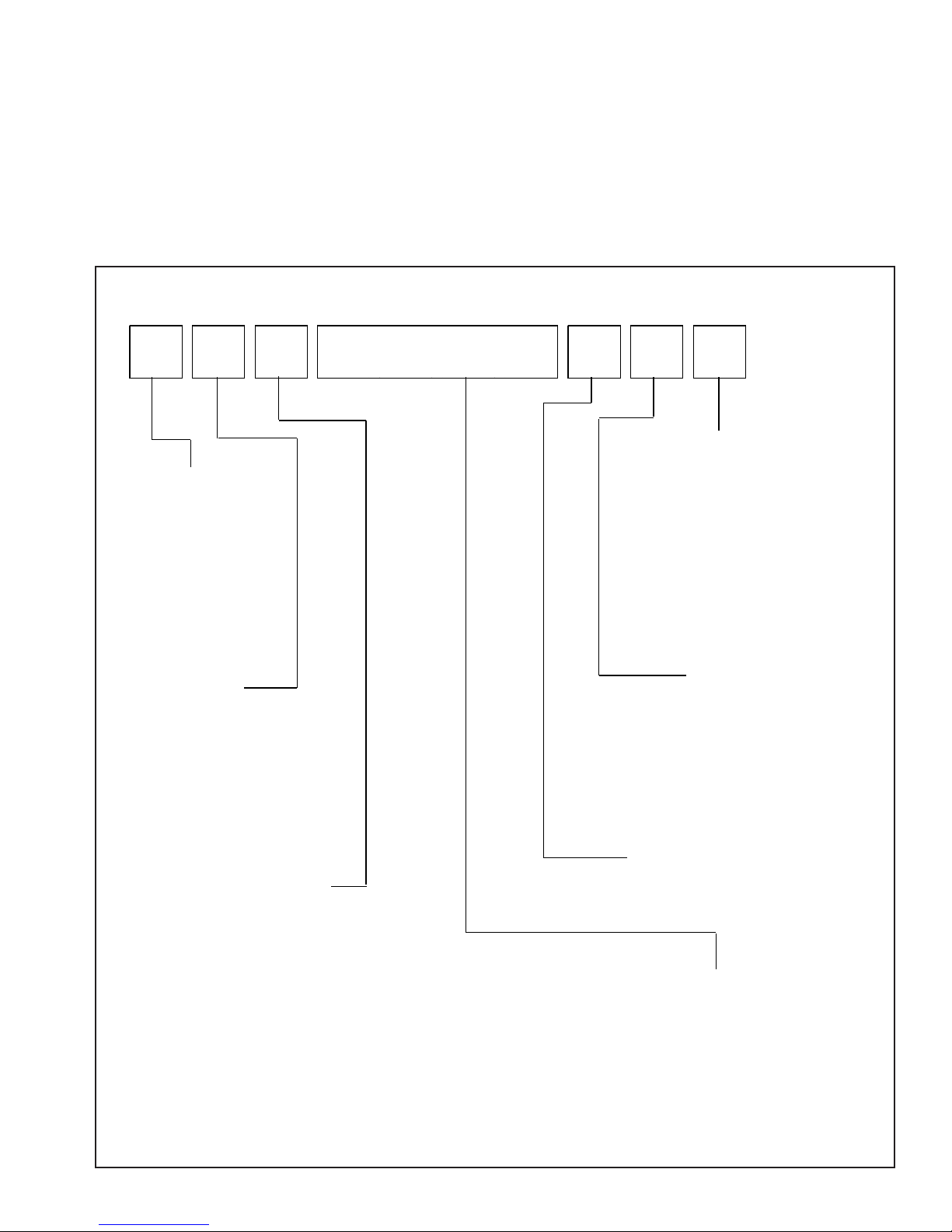
Cooking Nomenclature
A L Y 2 2 8 0 A D S
Color
A Almond on Almond
Brand
A Amana
C Magic Chef
G Graffer &
Sattler
H Hardwick
J Jenn-Air
M Maytag
N Norge
U Universal
Y Crosley
Fuel
B Butane
D Dual Fuel
E/J Electric
G Gas, Natural
L Liquid Propane
M Microwave
P Standing Pilot
X No Fuel
W Warming Drawer
Product Type
A Accessory/Cartridge
C Cooktop Updraft/Countertop
D Downdraft Cooktop or Warming Drawer
E Eyelevel Range
G Grill
L Range (20")
M Range (36")
P Drop In (24")
Q Wall Oven (27")
R Range, Free-Standing (30")
S Slide-In (30")
T Range Hood
V OTR
W Wall Oven
Y RV Range
Z RV Top
©2005 Maytag Services 16023515 7
B Black
C Brushed Chrome
H Traditional White
L Traditional Almond
P Prostyle
Q Monochromatic Bisque
S Stainless
T Traditional Bisque
W White on White
F Frost White (True Color White)
N Natural Bisque (True Color Bisque)
Listing
A UL/AGA
C CSA/CGA/CUL
D Dual Listed
G 220-240 V / 50-60 Hz
M Military Model
P PSB Approved
(Singapore)
X Export 120 V / 60 Hz
Production Code
This identifies the
production version.
Feature Content
1000-3999 Brands
4000-6999 Maytag/Amana
7000-9999 Jenn Air
Page 8
General Information
Specifications
Refer to individual Technical Sheet for specification
information.
Placement of the Oven or Cooktop
The freestanding range or cooktop must be placed in the
kitchen or comparable room. All safety guidelines must
be followed and free air flow around the range is
essential (see Chapter 2).
Do Not Block Air Vents
All air vents must be kept clear during cooking. If air
vents are covered during operation, the oven may
overheat. If this occurs, a sensitive, thermal safety device
automatically removes power to the oven, rendering the
oven inoperable. The oven will remain in this state until it
has sufficiently cooled.
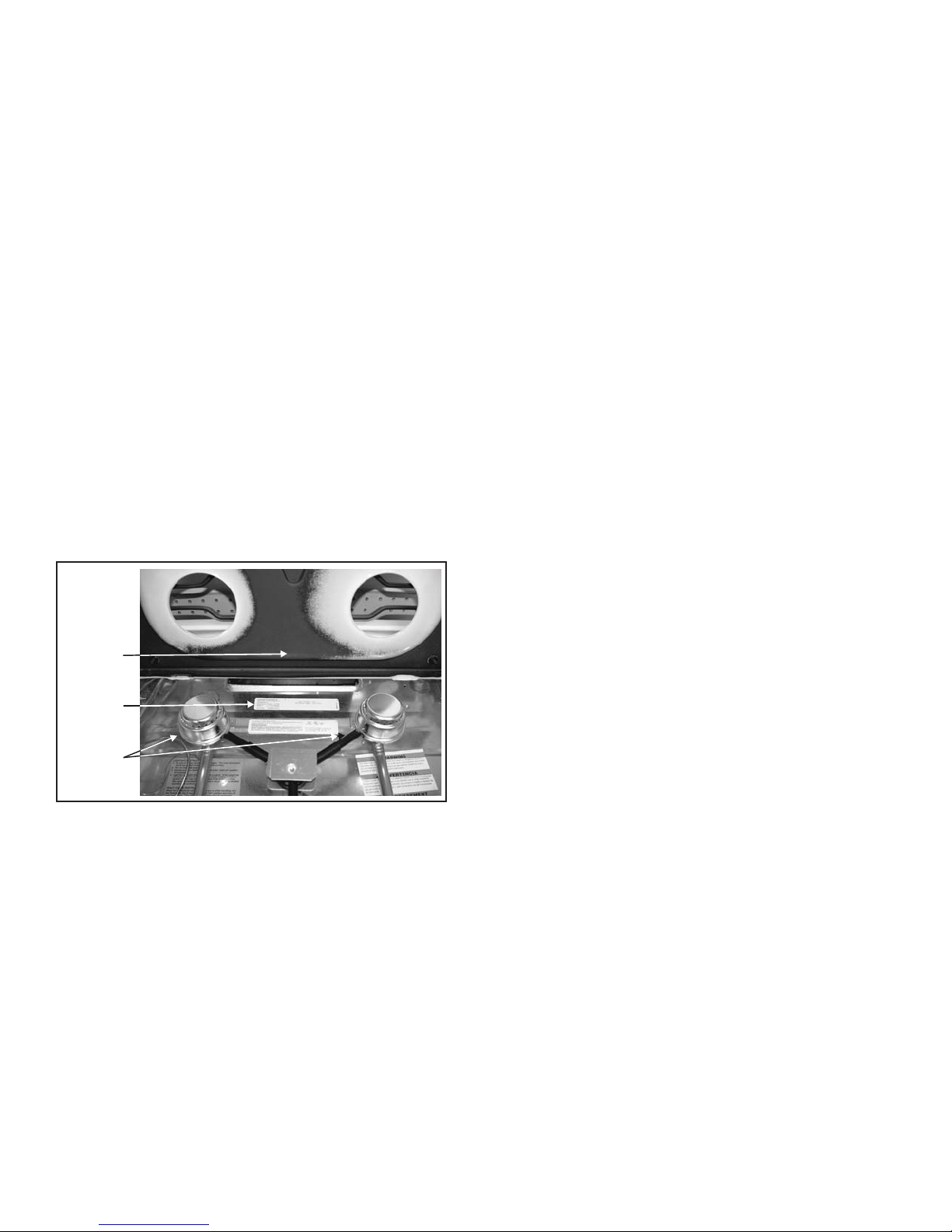
Location of Model Number
To request service information or replacement parts, the
service center will require the complete model, serial, and
manufacturing number of your freestanding range or
cooktop. The number can be found under the cooking
surface. Tilt the cooktop up to view the data.
Underside
of Cooking
Surface
Model
Number
Gas
Burners
Model Identification
Complete enclosed registration card and promptly return.
If registration card is missing:
• For Amana product call 1-800-843-0304 or visit the
Web Site at www.amana.com
• For Maytag product call 1-800-688-9900 or visit the
Web Site at www.maytag.com
• For product in Canada call 1-866-587-2002 or visit the
Web Site at www.maytag.com
When contacting provide product information located on
rating plate. Record the following:
Model Number: ___________________
Manufacturing Number: ___________________
Serial or S/N Number: ___________________
Date of purchase: ___________________
Dealer’s name and address: ___________________
Service
Keep a copy of sales receipt for future reference or in
case warranty service is required. To locate an authorized
servicer:
• For Amana product call 1-800-628-5782 or visit the
Web Site at www.amana.com
• For Maytag product call 1-800-462-9824 or visit the
Web Site at www.maytag.com
• For product in Canada call 1-866-587-2002 or visit the
Web Site at www.maytag.com
Warranty service must be performed by an authorized
servicer. We also recommend contacting an authorized
servicer, if service is required after warranty expires.
Parts and Accessories
Purchase replacement parts and accessories over the
phone. To order accessories for your product call:
• For Amana product call 1-877-232-6771 or visit the
Web Site at www.amana.com
• For Maytag product call 1-800-688-9900 or visit the
Web Site at www.maytag.com
• For product in Canada call 1-866-587-2002 or visit the
Web Sites at www.maytag.com
8 16023515 ©2005 Maytag Services
Extended Service Plan
We offer long-term service protection for this new oven
and cooktop.
• Dependability PlusSM Extended Service Plan is
specially designed to supplement Maytag’s warranty.
This plan covers parts, labor, and travel charges.
Call 1-800-925-2020 for information.
Page 9
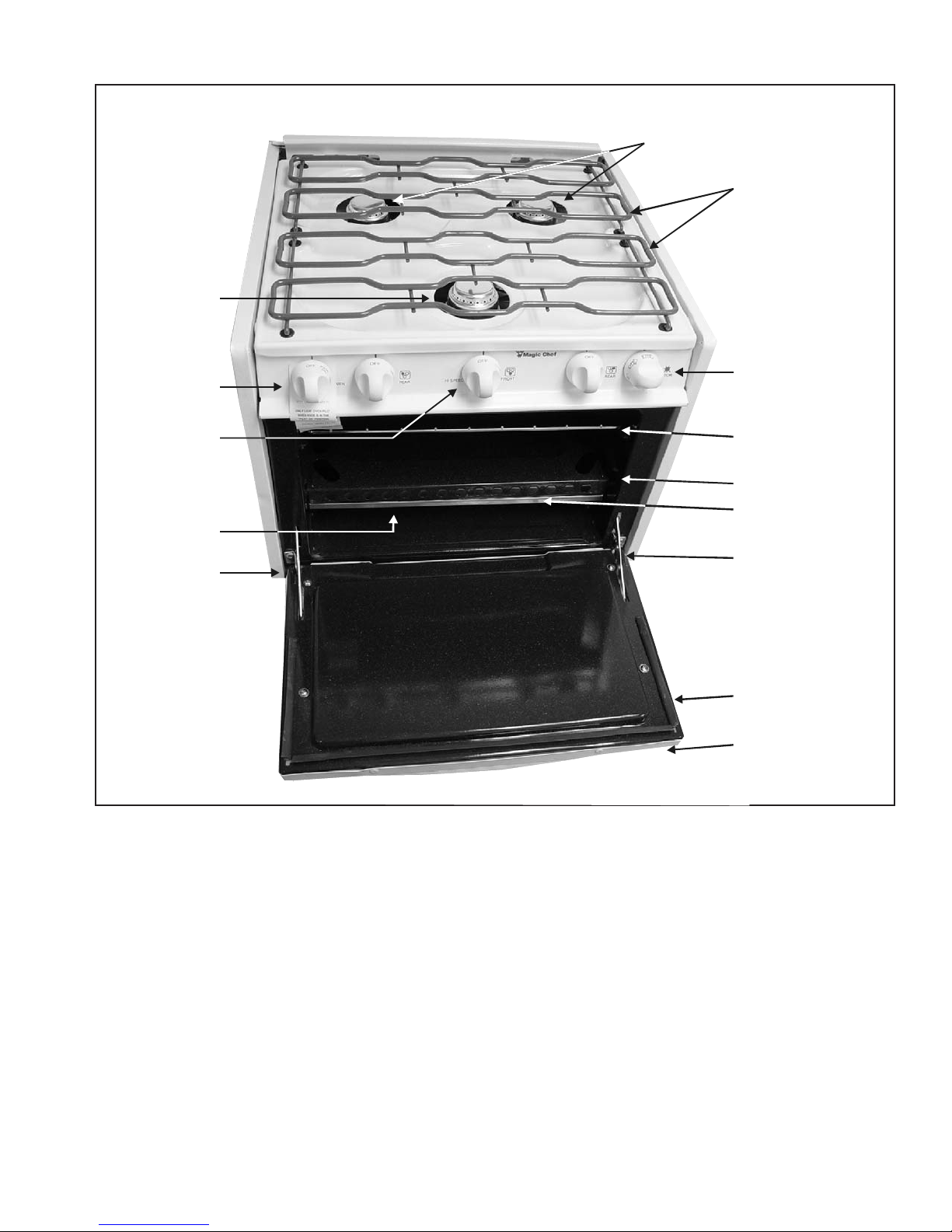
Range Description
Surface
Burner
Surface
Burners
Grates
Surface Burner
Control Knobs
Oven Burner
Control Knob
Oven Pilot
Door Hinge
Surface Burner
Control Knobs
Oven Rack
Oven Bottom Panel
Bake and
Broil Burner
Door Hinge
Oven Door
Door Handle
©2005 Maytag Services 16023515 9
Page 10
Troubleshooting Procedures
!
To avoid risk of electrical shock, personal injury, or death, disconnect power and gas before servicing, unless
testing requires power and/or gas.
WARNING
Troubleshooting Chart
Problem Possible Cause Correction
Surface burner fails to light.
Burner flame is uneven.
Surface burner flame lifts off
port or is yellow in color.
Oven burner fails to light.
Popping sound heard when
burner extinguishes.
Moisture condensation on
oven window (if equipped)
when oven is in use.
Baking results are not
satisfactory.
Oven smokes excessively
during broil.
Oven pilot will not light or
stay lit.
Oven smokes/odor first few
times of usage.
Clogged burner port(s) .............................
Surface control not completely turned to
the LITE position, or turned too quickly
from the LITE position ..............................
Damaged, wet or soiled burner ................
Clogged burner port(s) .............................
Air/gas mixture .........................................
Oven pilot not lit........................................
Improper oven control setting...................
This is a normal sound that occurs with
some types of gas when a hot burner is
turned off ..................................................
Moisture in oven .......................................
Moisture in oven window..........................
Oven not preheated or set to correct
temperature ..............................................
Oven thermostat sensing device not
inserted into clips......................................
Oven bottom panel incorrectly installed ...
Oven temperature set too high.................
Broil pan, broil area or oven soiled...........
Pilot tubing................................................
Gas pressure regulator.............................
Oven knob ................................................
Normal ......................................................
• Clean burner ports.
• Continue to turn the LITE control in
the direction indicated until the
burner ignites.
• Clean and/or dry burner, replace
burner if damaged.
• Clean burner ports.
• Adjust burner flame (some yellow
tipping with LP gas is acceptable).
• Light oven pilot. (See “Lighting Pilot
Burner,” page C-4.)
• Push in and turn oven control to
desired temperature.
• This is not a safety hazard and will
not damage the appliance.
• Leave oven door ajar for one or two
minutes to allow moisture to escape.
• Use a damp cloth to clean window to
prevent excess water from seeping
between the panels of glass.
• Preheat oven 10 to 15 minutes, or
set oven temperature to correct
temperature.
• Reinstall thermostat sensing device.
• Replace oven bottom correctly.
• Lower oven temperature.
• Clean broiler pan, broiler area or
oven.
• Pilot tubing may be clogged, kinked
or leaking at the fitting.
• Test pressure regulator, see Chapter
5, "Testing Procedures."
• Knob must be in PILOT ON position.
(See “Lighting Pilot Burner,”
page C-4.)
• Minor smoking and/or odor is normal
the first few times of oven usage.
10 16023515
©2005 Maytag Services
Page 11
Troubleshooting Procedures
.
.
.
!
To avoid risk of electrical shock, personal injury, or death, disconnect power and gas before servicing, unless
testing requires power and/or gas.
WARNING
Problem Possible Cause Correction
Gas odor.
Oven slow to heat, poor
baking results, poor burner
ignition, pilot won’t stay lit,
carbon on pilot shield, flame
too high or too low.
Gas leak ...................................................
Loose fittings ............................................
Pressure regulator....................................
• Check all gas connections for leaks
(see note below).
• Check all gas fittings for leaks.
• Test pressure regulator, see Chapter
5, "Testing Procedures."
NOTE: Due to vibrations that occur when traveling in a recreational vehicle, gas connections may loosen.
Periodically check all gas connections and gas fittings for leaks.
Never test for gas leaks using an open flame.
TESTING FOR GAS LEAKS: To test for a gas leak, apply a non-corrosive leak detection fluid to all joints and
fittings in the gas connection between the supply line, shut-off valve, and range or
cooktop. Include gas fittings and joints in the range or cooktop if connections were
disturbed during installation. Bubbles appearing around fittings and connections
indicates a leak. If a leak is present, turn off supply line gas shut-off valve, tighten
connections, turn on the supply line gas shut-off valve, and retest for leaks. When
finished, wipe off all residue.
©2005 Maytag Services 16023515 11
Page 12
Testing Procedures
!
WARNING
To avoid risk of electrical shock, personal injury or death; disconnect power and gas before servicing, unless
testing requires power and/or gas.
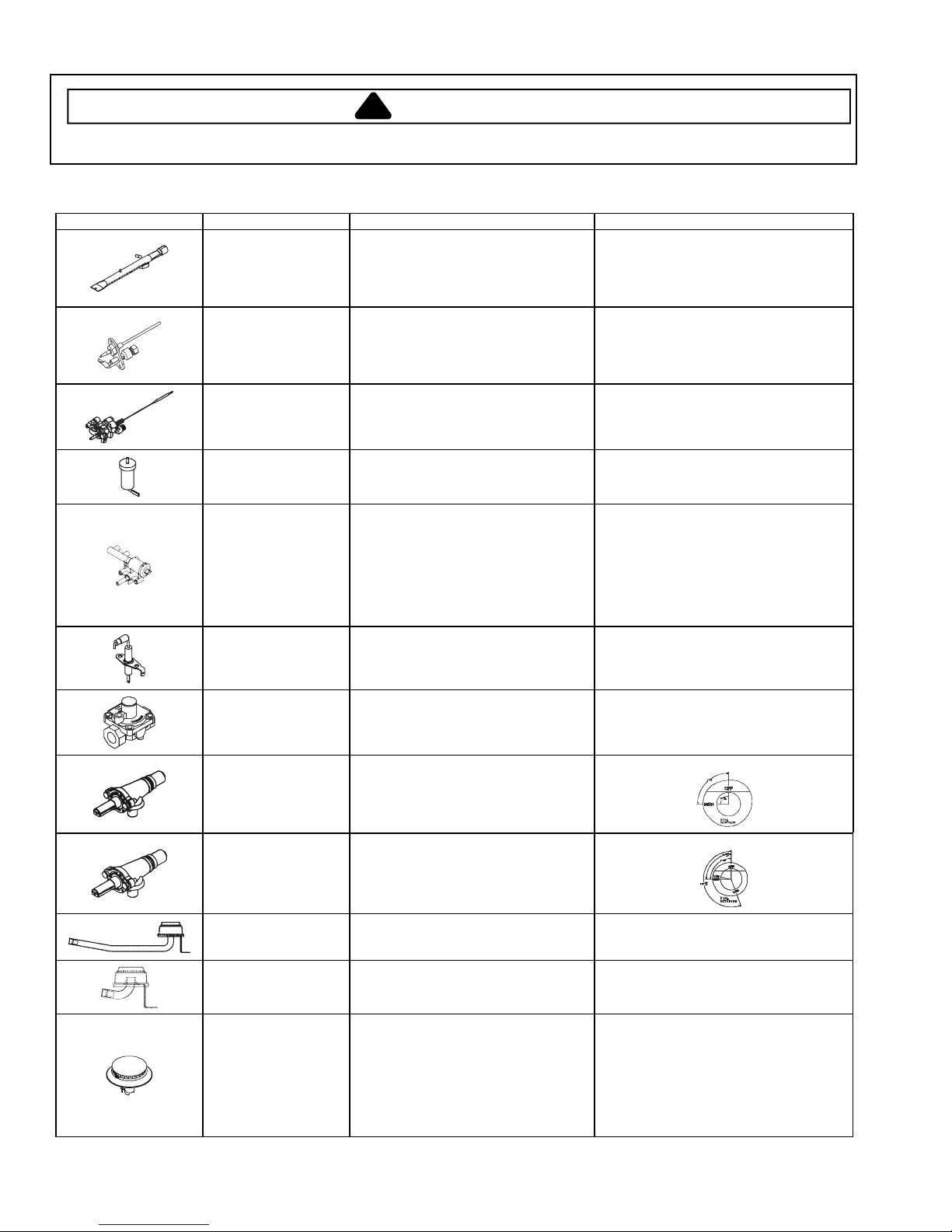
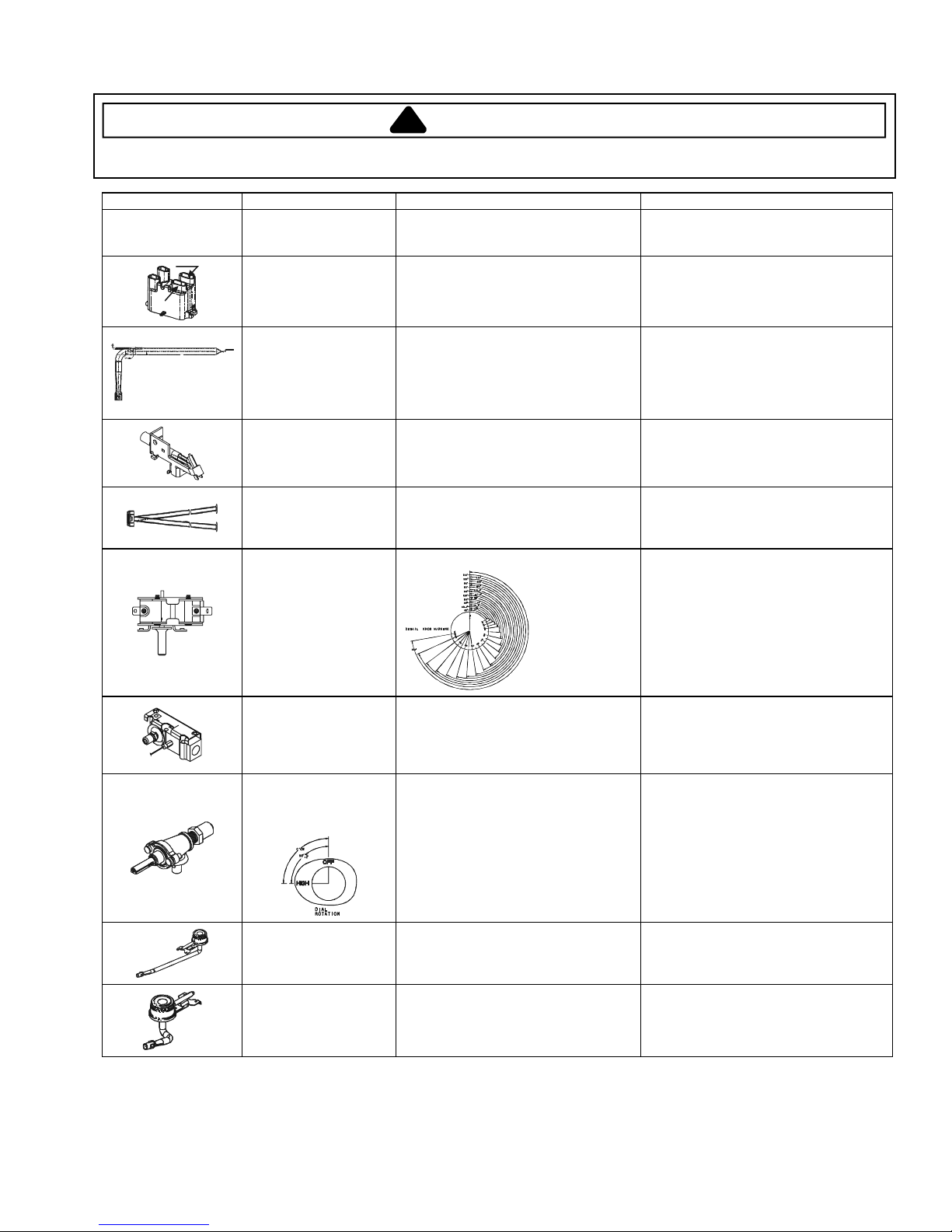
Component Testing Procedures
Illustration Component Test Procedure Results
Burner, bake
(Not applicable to
cooktop models.)
Burner, pilot
(Not applicable to
cooktop models.)
Thermostat, gas
Verify gas is supplied.
Check for obstructions, contamination
in ports or damage .................................
Verify gas is supplied.
Check for obstructions, contamination
in ports or damage .................................
Verify gas is supplied ............................. Gas is supplied.
(Copreci)
(Not applicable to
Spark ignitor, top
burners
Measure resistance from tip of spark
ignitor to wire terminal ............................ Continuity.
cooktop models.)
Ignitor, Piezo
(All models except
ALZ8590AD*,
Verify operation by rotating dial in the
direction indicated on the knob............... Ignitor clicks and top burner spark ignitor
CG11000AD*,
CPL1110AD*,
YPL1110AD*,
CLY2210BD*,
CLY1610BD*)
Electrode, top burner
electrode
(Models
Measure resistance from tip of
electrode to wire terminal ....................... Continuity.
ALZ8580AD*,
ALZ8589AD*)
Regulator, pressure Verify gas pressure (WCP).....................
Air shutter opening: .438" to .498".
Blue flame with some yellow tipping is
normal (burner should not soot).
Replace if punctured or torn.
Orifice diameter: .0078" to .0086".
Blue flame with some yellow tipping is
normal (burner should not soot).
Replace if punctured or torn.
emits a spark.
10" LP/Propane.
Valve, top burner
Verify gas is supplied ............................. Gas is supplied.
(6.5K burners)
Valve, top burner
Verify gas is supplied ............................. Gas is supplied.
(9.1K burner)
Burner, top rear,
sealed (6.5K burners)
Burner, top front,
sealed (9.1K burner)
Burner, top, sealed
(Models
ALY1680BD*,
Verify gas is supplied .............................
Check for obstructions or
contamination in burner ports.................
Verify gas is supplied .............................
Check for obstructions or
contamination in burner ports.................
Verify gas is supplied .............................
Check for obstructions or
contamination in burner ports.................
Gas is supplied.
Clean/remove any foreign objects.
Gas is supplied.
Clean/remove any foreign objects.
Gas is supplied.
Clean/remove any foreign objects.
ALY2280BD*,
ALY2289BD*,
ALZ8580AD*,
ALZ8589AD*,
ALZ8590AD*)
12 16023515
©2005 Maytag Services
Page 13
Testing Procedures
!
WARNING
To avoid risk of electrical shock, personal injury or death; disconnect power and gas before servicing, unless
testing requires power and/or gas.
Illustration Component Test Procedure Results
B
Switch, lighter
(Model ALZ8590AD*)
Module, spark
(Model ALZ8590AD*)
A
Burner, bake
(Models CPL1110AD*,
YPL1110AD*,
CG11000AD*)
Lighter, pilot
(Models CPL1110AD*,
YPL1110AD*,
CG11000AD*)
Burner, pilot
(Models CPL1110AD*,
YPL1110AD*,
CG11000AD*)
Thermostat, gas
(Models CPL1110AD*,
YPL1110AD*,
CG11000AD*)
Verify operation by rotating dial in the
direction indicated on the knob .............. Ignitor clicks and top burner spark
ignitor emits a spark.
Test for voltage at terminals A and B .....
Check polarity and ground .....................
Verify gas is supplied.
Verify air shutter adjustment ..................
Verify proper orifice installed-Nat or LP..
Check for obstructions, contamination
in ports or damage .................................
Verify gas pressure (WCP) ....................
12 VDC.
See schematic drawing.
Air shutter opening: .349" to .411".
Refer to LP/Nat. conversion instructions.
Blue flame with some yellow tipping is
normal (burner should not soot).
Replace if punctured or torn.
" Natural
4
" LP/Propane
10
Verify pilot selector cartridge is set to
the proper gas........................................ LP or Natural
Verify gas is supplied .............................
Gas is supplied.
Safety valve, oven,
Verify gas supply is turned on ................ Gas is turned on.
shut-off
(Models CPL1110AD*,
YPL1110AD*,
CG11000AD*)
Valve, top burner
(Models CPL1110AD*,
YPL1110AD*,
CG11000AD*)
Verify gas is supplied .............................
Orifice adjusted for Natural or LP ...........
Gas is supplied.
Refer to LP/Nat. conversion
instructions.
Adjust set screw for simmer control.
Burner, open, top rear
(Models CPL1110AD*,
YPL1110AD*,
CG11000AD*)
Burner, open, top front
(Models CPL1110AD*,
YPL1110AD*,
CG11000AD*)
Verify gas is supplied .............................
Verify air shutter adjusted properly.........
Gas is supplied.
Air shutter opening: .420" to .460"
Verify gas is supplied .............................
Verify air shutter adjusted properly.........
Gas is supplied.
Air shutter opening: .420" to .460"
©2005 Maytag Services 16023515 13
Page 14

Disassembly Procedures
b
To avoid risk of electrical shock, personal injury or
death; disconnect power and gas before servicing.
Replacing Range/Cooktop
1. Turn off and remove power from unit (if electric unit).
2. Turn off and remove gas supply from unit.
NOTE: To avoid countertop damage, do not move
range forward or cooktop up until raised enough
to clear all cabinetry.
3. Pull the range forward out of the cabinet opening, or
pull the cooktop up and out of the installation location.
4. Replace the range/cooktop using the installation
instructions and anti-tip bracket(s).
Replacing Open Surface Burner (Select
Models)
1. Turn off and remove power from unit (if electric unit).
2. Turn off and remove gas supply from unit.
3. Remove surface grates and lift cooking surface.
4. Remove burner flashtube extender from burner.
5. Remove screw securing burner to chassis.
6. Remove burner gas tubing from burner control valve.
7. Reverse procedures to reassemble.
NOTE: Perform gas leak test.
4. Place Burner Wrench removal and installation tool
(Part Number 8312D075-60) over sealed burner (see
wrench label for proper alignment).
5. Once the wrench is placed properly on the burner,
turn wrench counterclockwise with steady and even
pressure. Turn the burner no more than two inches
to loosen.
NOTE: Some minor crunching or grinding sounds may
be heard. This is normal. Be careful not to chip
the finish in visible areas.
6. Once loose, lift the burner straight up and out of the
mounting hole.
7. Disconnect ignitor wire.
8. Reverse procedures to reassemble.
NOTE: Perform gas leak test.
This gap
fits over
the ignitor.
Ignitor
Flashtube
Assembly
Ignitor
Front Open
Burner
Burner Control
Valv e
Burner Control
Knobs
Oven Control
Valv e
Manifold
Assembly
Regulator
Ignitor Control
Knob
Grates
Maintop
Rear Open
Burner
Gas
Fitting
Ignitor Control
Open Burner Surface Gas Controls
Replacing Sealed Surface Burner (Select
Models)
1. Turn off and remove power from unit (if electric unit).
2. Turn off and remove gas supply from unit.
3. Remove surface grates from cooking surface.
Sealed
Burner
Oven Control
Val ve
Burner Control
Knobs
Front Burner
Orifice
Burner Control
Val ve
Manifold
Assembly
Grates
Maintop
Pressure
Regulator
Rear Burner
Orifice
Gas Fitting
Ignitor Control
Ignitor Control
Kno
Sealed Burner Surface Gas Controls
Replacing Sealed Surface Burner Orifice
(Select Models)
1. Turn off and remove power from unit (if electric unit).
2. Turn off and remove gas supply from unit.
14 16023515 ©2005 Maytag Services
Page 15

Disassembly Procedures
To avoid risk of electrical shock, personal injury or
death; disconnect power and gas before servicing.
3. Remove maintop assembly, see "Replacing Maintop
Assembly" procedure.
4. Remove screws securing burner orifice assembly to
burner box.
5. Disconnect orifice assembly from burner control
valve.
6. Reverse procedures to reassemble.
NOTE: Perform gas leak test.
Replacing Maintop Assembly
1. Turn off and remove power from unit (if electric unit).
2. Turn off and remove gas supply from unit.
3. Lift left side of top up and slide top off guide pin.
4. Slide right side of top toward the left and off guide pin.
5. Set maintop assembly in a safe location.
6. Reverse procedures to reassemble.
Replacing Manifold Assembly
1. Turn off and remove power from unit (if electric unit).
2. Turn off and remove gas supply from unit.
3. Remove maintop assembly, see "Replacing Maintop
Assembly" procedure.
4. Remove gas supply line from pressure regulator.
5. Remove surface burners. Depending on model, see
either "Replacing Open Surface Burner" procedure or
"Replacing Sealed Surface Burner Assembly"
procedure.
6. Remove gas valve control knobs from control panel.
7. Disconnect all gas lines from oven control valve.
8. Remove screws securing manifold to chassis.
9. Open oven door and remove thermostat sensor from
retaining clip.
10.Gently slide sensor up and out of oven cavity using
the installation hole located in the top of the oven
cavity.
11. Slide manifold assembly from burner box.
12.Reverse procedures to reassemble.
Replacing Surface Burner Valve Control
Assembly
1. Turn off and remove power from unit (if electric unit).
2. Turn off and remove gas supply from unit.
3. Remove manifold assembly, see "Replacing Manifold
Assembly" procedure.
4. Remove screw securing surface burner control valve
to manifold.
5. Slide surface burner control valve from manifold
assembly.
6. Reverse procedures to reassemble.
(Select Models)
Replacing Igniter Assembly (Select Models)
1. Turn off and remove power from unit (if electric unit).
2. Turn off and remove gas supply from unit.
3. Remove ignitor control knob.
4. Remove screws securing assembly to control panel.
5. Remove wire to electrode.
6. Slide igniter assembly from control panel/burner box.
7. Reverse procedures to reassemble.
Replacing Control Panel Assembly
1. Remove unit from installation position, see “Replacing
Range/Cooktop” procedure.
2. Remove maintop, see "Replacing Maintop Assembly"
procedure.
3. Remove valve control knobs.
4. Remove ignitor control knob (select models).
5. Remove screws securing control panel to chassis.
6. Reverse procedures to reassemble.
NOTE: Perform gas leak test.
Replacing Regulator
1. Turn off and remove power from unit (if electric unit).
2. Turn off and remove gas supply from unit.
3. Disconnect gas supply lines from regulator.
4. Remove manifold assembly, see "Replacing Manifold
Assembly" procedure.
5. Remove regulator from manifold assembly.
6. Reverse procedures to reassemble.
NOTE: When reconnecting supply line to regulator, use
pipe dope compound to seal the connection.
Once connected, perform gas leak test.
Replacing Flashtube Assembly (Select
Models)
1. Turn off and remove power from unit (if electric unit).
2. Turn off and remove gas supply from unit.
3. Lift up on maintop assembly to access burner box.
4. Disconnect flashtube extensions from burners.
5. Disconnect ignitor wire.
6. Remove screws securing flashtube assembly to
chassis.
7. Slide flashtube assembly from burner box.
8. Reverse procedures to reassemble.
NOTE: Perform gas leak test.
Replacing Oven Control Valve (Select
Models)
1. Turn off and remove power from unit (if electric unit).
2. Turn off and remove gas supply from unit.
3. Remove manifold assembly, see "Replacing Manifold
Assembly" procedure.
4. Remove screw securing oven control valve to
manifold.
5. Slide oven control valve from manifold assembly.
6. Reverse procedures to reassemble.
©2005 Maytag Services 16023515 15
Page 16

Disassembly Procedures
y
Thermostat
Sensor
Burner Baffle Plate
Oven/Safety Valve or
Elbow Block Assembl
Bake Burner
Pilot Burner
Assembly
To avoid risk of electrical shock, personal injury or
death; disconnect power and gas before servicing.
6. Disconnect gas lines to oven and pilot burners.
7. Remove screws securing burner holder to oven
chassis.
8. Remove screws securing pilot burner assembly to
bake burner.
9. Gently slide pilot assembly toward the front of the
oven to remove.
10.Reverse procedures to reassemble.
Replacing Oven Bottom Plate (Select
Models)
1. Turn oven off.
2. Open oven door and remove baking racks.
3. Push oven bottom plate in, slide up, then pull plate
toward the front of the oven once the plate has
cleared the guide pins.
4. Slide oven bottom plate out of oven cavity.
5. Reverse procedures to reassemble.
Oven Cavity Gas Controls
Replacing Oven/Safety Valve (Select Models)
1. Turn off and remove power from unit (if electric unit).
2. Turn off and remove gas supply from unit.
3. Open oven door and remove baking racks.
4. Remove oven bottom plate, see "Replacing Oven
Bottom Plate" procedure.
5. Disconnect gas supply lines from oven/safety valve.
6. Remove screws securing oven/safety valve to rear
wall of oven cavity.
7. Remove oven/safety valve from oven cavity.
8. Reverse procedures to reassemble.
Replacing Bake Burner (Select Models)
1. Turn off and remove power from unit (if electric unit).
2. Turn off and remove gas supply from unit.
3. Open oven door and remove baking racks.
4. Remove oven bottom plate, see "Replacing Oven
Bottom Plate" procedure.
5. Remove screw securing baffle to burner.
6. Disconnect gas lines to oven and pilot burners.
7. Remove screws securing burner holder to oven
chassis.
8. Remove screws securing pilot burner assembly to
bake burner. Gently slide pilot assembly out.
9. Slide bake burner toward front of oven and remove.
10.Reverse procedures to reassemble.
Replacing Elbow Block Assembly (Select
Models)
1. Turn off and remove power from unit (if electric unit).
2. Turn off and remove gas supply from unit.
3. Open oven door and remove baking racks.
4. Remove oven bottom plate, see "Replacing Oven
Bottom Plate" procedure.
5. Disconnect gas supply line from elbow block
assembly.
6. Remove screws securing elbow block assembly to
rear wall of oven cavity.
7. Remove elbow block assembly from oven cavity.
8. Reverse procedures to reassemble.
Replacing Thermostat Sensor (Select
Models)
1. Turn off and remove power from unit (if electric unit).
2. Turn off and remove gas supply from unit.
3. Remove manifold assembly, see "Replacing Manifold
Assembly" procedure.
4. Remove screw securing oven control valve to
manifold.
5. Slide oven control valve from manifold assembly.
6. Reverse procedures to reassemble.
NOTE: The individual sensor cannot be replaced. The
complete oven control valve assembly must be
replaced.
Replacing Oven Pilot Burner (Select Models)
1. Turn off and remove power from unit (if electric unit).
2. Turn off and remove gas supply from unit.
3. Open oven door and remove baking racks.
4. Remove oven bottom plate, see "Replacing Oven
Bottom Plate" procedure.
5. Remove screw securing baffle to burner.
16 16023515 ©2005 Maytag Services
Replacing Oven Flue Box Assembly (Select
Models)
1. Turn off and remove power from unit (if electric unit).
2. Turn off and remove gas supply from unit.
3. Open oven door and remove baking racks.
4. Remove screws securing bottom of oven flue box
assembly to rear wall of oven cavity.
Page 17

Disassembly Procedures
g
g
To avoid risk of electrical shock, personal injury or
death; disconnect power and gas before servicing.
5. Slide vent up and out to remove flue box.
6. Reverse procedures to reassemble.
Oven Hin
Flue Box
Main Back
e Sprin
Burner Box Bottom
Side Trim
Control Panel
Oven Rack
Oven Cavi ty
Oven Bot tom
Range Components, Oven and Frame
Replacing Main Back
1. Remove unit from installation position, see “Replacing
Range/Cooktop” procedure.
2. Remove maintop, see "Replacing Maintop Assembly"
procedure.
3. Remove screws securing main back to chassis.
4. Reverse procedures to reassemble.
Replacing Side Trim
1. Remove unit from installation position, see “Replacing
Range/Cooktop” procedure.
2. Remove maintop, see "Replacing Maintop Assembly"
procedure.
3. Remove screws securing maintop guide pins to side
trim.
4. Remove bolt and nut securing side trim to chassis.
5. Remove screws securing side trim to chassis.
6. Slide side trim up and toward the front to remove.
7. Reverse procedures to reassembly.
4. Remove screws securing door panel to inner door
(also glass panel on select models).
5. Remove screws securing bottom oven door bracket
to oven chassis.
6. Remove screws securing inner door to hinge
receptacles.
7. Pull and slide hinge spring arms away from hinge
receptacles.
8. Hook spring arms into oven chassis hinge slots until
reassembly.
9. Reverse procedures to reassemble.
Replacing Oven Door Handle (Select Models)
WARNI NG
!
To avoid risk of personal injury or property damage,
do not lift oven door by the handle.
1. Turn off and remove power from unit (if electric unit).
2. Turn off and remove gas supply from unit.
3. Open oven door.
4. Remove screws securing door panel to inner door
(also glass panel on select models).
5. Remove screws securing oven door handle to oven
door (also glass panel on select models).
6. Reverse procedures to reassemble.
Replacing Oven Door Hinge (Select Models)
WARNI NG
!
To avoid risk of personal injury or property damage,
do not lift oven door by the handle.
1. Remove oven door, see "Oven Door Removal"
procedure.
2. Slide hinge out from inner door assembly.
3. Reverse procedures to reassemble.
Oven Door Removal (Select Models)
WARNI NG
!
To avoid risk of personal injury or property damage,
do not lift oven door by the handle.
1. Turn off and remove power from unit (if electric unit).
2. Turn off and remove gas supply from unit.
3. Open oven door.
©2005 Maytag Services 16023515 17
Page 18

Disassembly Procedures
y
To avoid risk of electrical shock, personal injury or
death; disconnect power and gas before servicing.
Oven Door Disassembly (Select Models)
1. Remove oven door, see "Replacing Oven Door" procedure.
2. Remove oven door handle, see "Replacing Oven Door Handle" procedure.
3. Reverse procedure to reassemble oven door.
Door
Lining
Glass
Door
(select models)
Door
Handle
Glass Clip
Door
Panel
Door
Insulation
Replacing Spark Module (Model ALZ8590AD*)
1. Turn off and remove power from unit (if electric unit).
2. Turn off and remove gas supply from unit.
3. Remove maintop, see "Replacing Maintop Assembly" procedure.
4. Remove screws securing spark module to chassis.
5. Slide spark module up to remove.
6. Reverse procedures to reassemble.
Hinge Spring
Door Hinge
Grate
Sealed
Burner
Drip
Bowl
Ta p e
Seal
To p / G la s s
Assembly
Burner
Control
Knob
18 16023515 ©2005 Maytag Services
Burner
Bottom
Glass
Grommet
Burner
Orifice
Box
Ignitor
Regulator
Switch
Manifold
Assembl
Burner Control
Valve
Cooktop Model ALZ8590AD* Components
Page 19

Appendix A
©2005 Maytag Services 16023515 A – 1
Page 20

Installation Instructions (All models except ALZ8590AD*, CPL1110AD*,
YPL1110AD*, CG11000AD*)
For RV Cooktop s
6.
INSTALLATION
1. Cut opening in accordance with diagram shown below.
2. Align the 3/8" gas supply line with the hole provided in
burner box so it will slide into place when the range is
placed into the opening.
3. Place the range in position and fasten down with four
wood screws through holes provided in the side trim.
4. Connect gas supply line.
5. Check all gas connections for leaks with non-corrosive
leak detection fluid.
checking gas leaks.
Do not use open flames for
CAUTION:
GASSUPPLYLINEMUSTHAVEAL.P.GAS
PRESSURE REGULATOR. INLET PRESSURE TO
THIS APPLIANCE SHOULD BE REDUCED TO A
MAXIMUM OF 14 INCHES WATER COLUMN (0.5
P.S.I.) INLET PRESSURES IN EXCESS OF 0.5 P.S.I.
CAN DAMAGE THE APPLIANCE PRESSURE
REGULATOR AND OTHER GAS COMPONENTS IN
THIS APPLIANCE AND CAN RESULT IN A GAS
LEAK.
WARNING:
fused to metal. It is thoroughly inspected and will give
good service if carefully handled, but it is breakable and
cannot be guaranteed. Like all glass or porcelain articles,
we cannot replace enamel parts that are damaged after
delivery to carriers except at customer’s expense.
LIQUIFIED PETROLEUM (L.P.)/PROPANE
Porcelain enamel is glass which has been
Min. Vertical
Back Wall 7/8
11/2 Min.
to Vertical
Side Wal l
43/8
Front Cut-out
NOTE:
Clearance spaces shall be framed in or
7
21 7/16
20 1/2
18 9/16
23/4
If countertop has overhang, it must be
notched to suit 21 7/16 dimension.
Countertop overhang in excess of 1 will
require radius return to tri m of range.
Min. Distance
to side wall 1 1/16
Front Cut-out 4 3/8
guarded to prevent storage space within the
clearance specified. Cabinet enclosures shall
be designedto prevent drafts that will affect pilot
stability.
Minimum clearances zero from intergral
casing spacers below countertop.
21 3/8
Dottedlineindicates
top trim
7
20 1/2
11/16
23/4
Service
Pipe
Opening
Min. distance to back wall
18 9/16
7/16
Range to be supported
on countertop only
Top T ri m
Overlap
7/8
41/2
A – 2 16023515 ©2005 Maytag Services
Page 21

Installation Instructions (All models except ALZ8590AD*, CPL1110AD*,
YPL1110AD*, CG11000AD*)
For RV Ranges
INSTALLATION
1. Cut opening as shown below (range can be suspended
from top flange; no other support is necessary.)
2. Range equipped with a 120 volt light in the oven will
require the installation of a 120V three prong grounded
receptacle directly behind the range (for correct
location see sketch below.) On range with BX cable
and marked for 12 volt DC power supply connect 12
volt DC power to the tagged wires.
3. Place range in opening and fasten in place. Six screw
holes that are provided are located at points AA and
BB. A minimum of four screws must be used to fasten
range. Recreational vehicle manufacturers may use
appropriate holes as found necessary to suit the
application. Use No. 8 flat head wood screws.
4. Make gas connections and check for leaks with non
corrosive leak detection fluid.
with open flame.
Do not check for leaks
5.
CAUTION:
GASSUPPLYLINEMUSTHAVEAL.P.GAS
PRESSURE REGULATOR. INLET PRESSURE TO
THIS APPLIANCE SHOULD BE REDUCED TO A
MAXIMUM OF 14 INCHES WATER COLUMN (0.5
P.S.I.) INLET PRESSURES IN EXCESS OF 0.5 P.S.I.
CAN DAMAGE THE APPLIANCE PRESSURE
REGULATOR AND OTHER GAS COMPONENTS IN
THIS APPLIANCE AND CAN RESULT IN A GAS
LEAK.
WARNING:
fused to metal. It is thoroughly inspected and will give
good service if carefully handled, but it is breakable and
cannot be guaranteed. Like all glass or porcelain articles,
we cannot replace enamel parts that are damaged after
delivery to carriers except at customer’s expense.
LIQUIFIED PETROLEUM (L.P.)/PROPANE
Porcelain enamel is glass which has been
NOTE:
Clearance spaces shall be framed
in or guarded to prevent storage space
within the clearance specified. Cabinet
enclosures shall be designed to prevent
drafts that will affect pilot stability.
MODEL
16
22
©2005 Maytag Services 16023515 A – 3
CUTOUT HT.
16 3/8
21 13/16
PIPE LOC.
17/8
25/8
Page 22

Installation Instructions (All models except ALZ8590AD*, CPL1110AD*,
YPL1110AD*, CG11000AD*)
OVEN SECTION
1. The oven thermostat in this range will enable you to turn
off the Oven Constant Pilot by simply turning the
thermostat dial to the “OFF” position. To light oven pilot,
push the Control knob and rotate counter clockwise to
the “OVEN PILOT ON” position. Push and hold the
control knob while lighting the oven standing pilot.
2. The air shutter has been adjusted at the factory,
however, it may require some additional adjustment
when used at high altitudes.
3. To adjust, open the air shutter to the full open position
where you will have a blowing condition. Begin closing
the shutter slowly, when you reach the correct
adjustment the blowing will stop and the burner should
have a sharp blue flame approximately 3 inches long.
4. There is no oven pilot adjustment on the thermostat, the
control has been factory preset for use on LP gas, no
field adjustment necessary.
RECOMMENDED GROUNDING METHOD
ELECTRICAL REQUIREMENTS AND GROUNDING
INSTRUCTIONS FOR 120V 60HZ AC,
if equipped.
FIGURE 1
NOTE:
electrically grounded in accordance with National Electric
Code. ANSI/NFPA No. 70-1990. In Canada CAN/CSA C22.2 Electrical Code.
A unit having an external electrical supply must be
WIRING DIAGRAM FOR MODELS WITH
EXTERNAL ELECTRICAL SUPPLY
Observe all governing codes and ordinances. All ranges
requiring electrical supply must be grounded.
If this appliance is factory equipped with a power supply
cord it has a three-pronged grounding plug. It must be
plugged into a mating grounding type receptacle in
accordance with National Electrical Code and applicable
local codes and ordinances. If the circuit does not have a
grounding type receptacle, it is the responsibility and
obligation of the customer to change the existing
receptacle to a proper grounded receptacle in accordance
with the National Electrical Code and applicable local
codes and ordinances.
PRONGSHOULDNOT,UNDERANY
CIRCUMSTANCES, BE CUT OR REMOVED as it
provides protection against shock hazard.
THE THIRD GROUNDING
A – 4 16023515 ©2005 Maytag Services
Page 23

Installation Instructions (Model ALZ8590AD*)
Note To Installer
Always check with local and state codes before
installation. Requirements beyond those as shown may
affect these instructions, for which the manufacturer is not
responsible.
The installation of appliances designed for recreational
vehicles must conform with state or provincial codes, or in
the absence of such codes, with the latest edition of the
Standard for Recreational Vehicles ANSI/NFPA No.
501C.
CUL appliance must be installed in accordance with
CAN/CSA Z240.4 Series Standards, “Gas equipped
recreational vehicles and mobile homes” and/or local
codes having jurisdiction. Minimum clearance from
countertop to combustible ceiling as approved by U.L. is
24 , CUL is 19 .
Rating Plate Location
The rating plate is located under the cooktop. The
following information is listed on this plate:
The model and serial numbers.
When inquiring about your appliance be sure to include
these numbers with your inquiry.
For your convenience please record these numbers in the
space provided below.
1. Model number:
2. Serial number:
WIRING DIAGRAM FOR MODELS WITH EXTERNAL ELECTRICAL SUPPLY
©2005 Maytag Services 16023515 A – 5
Page 24

Installation Instructions (Model ALZ8590AD*)
Installation For RV Cooktops
1.
CAUTION:
LIQUIFIED PETROLEUM (L.P.)/PROPANEGASSUPPLYLINEMUSTHAVEAL.P.GAS
PRESSURE REGULATOR. INLET PRESSURE TO
THIS APPLIANCE SHOULD BE REDUCED TO A
MAXIMUM OF 14 INCHES WATER COLUMN (0.5
P.S.I.) INLET PRESSURES IN EXCESS OF 0.5 P.S.I.
CAN DAMAGE THE APPLIANCE PRESSURE
REGULATOR AND OTHER GAS COMPONENTS IN
THIS APPLIANCE AND CAN RESULT IN A GAS
LEAK.
3
20
15
2. Cut opening in accordance with figure 1 shown below.
3MIN.TO
REAR WALL
3 MIN. TO SIDE WALLS
3. Place the cooktop upside down on a protected surface
and place the 1/2 x 1/2 foam strip on the underside of
the glass around the perimeter of cooktop to seal
between cooktop and counter. (See figure 2).
4. Place the cooktop in position and fasten down with
screws and mounting brackets. (See figure 2).
FOAM
GASKET
Ar t #: 9215- 188
MOUNTING BRACKET
MOUNTING SCREW
Figure 2
PRIOR TO STEPS 5 & 6, MAKE SURE BOTH KNOBS
ARE IN THE “OFF
”POSITION.
5. Connect ignition wires to 12 VOLT DC power source,
as shown in figure 3. (Black to negative and Red to
positive).
6. Connect gas supply line to .625-18UNF-2A nipple at
back of unit. (See figure 3).
NOTE:
If local codes and ordinances permit, A.G.A.
design certified, new flexible metal tubing is recommended for connecting cooktop to the gas supply line.
7. Check all gas connections for leaks with non corrosive
leak detection fluid.
Do not use open flames for
checking gas leaks.
FLEXIBLE CONNECTOR
SHUTOFF
20 15
VALV E
Figure 1
FLEXIBLE CONDUIT
BLACK TO (-) NEGATIVE
RED TO (+) POSITIVE
POWER SOURCE: 9 TO 12 VDC
Figure 3
A – 6 16023515 ©2005 Maytag Services
Page 25

Installation Instructions (Model ALZ8590AD*)
WARNING:
Porcelain enamel is glass which
has been fused to metal. It is thoroughly inspected
and will give good service if carefully handled, but
it is breakable and cannot be guaranteed. Like all
glass or porcelain articles, we cannot replace
enamel parts that are damaged after delivery to
carriers except at customer’s expense.
CHECK THESE POINTS BEFORE YOU CALL FOR SERVICE
PROBLEM
CAUSE
Insertion And Removal Of SqueezeGrate
Press on two grate fingers on both sides of expansion gap
and insert or remove squeeze grate from burner bowl.
(See figure 4).
EXPANSION GAP
PRESS HERE
GRATE
FINGER
BURNER
BOWL
PRESS HERE
Ar t #: 9215- 189
Figure 4
CORRECTION
Surface burner fails to light.
Burner flame is uneven.
Surfaceburner flamelifts off port
or is yellow in color.
Popping sound heard when
burner extinguishes.
Gas odor
a. Clogged burner port(s).
b. Surface control not completely turned
to the LITE position or turned too
quickly from the LITE position.
c. Burner will not light if the ignitor is
damaged, soiled, wet or if the port
directly below the ignitor is blocked.
Clogged burner port(s).
Air/gas mixture not proper.
NOTE:
is normal and acceptable.
This is a normal sound that occurs with some types of gas when a hot burner is
turned off. The popping sound is not a safety hazard and will not damage the
appliance.
Possible leak or loose fittings.
Some yellow tipping with LP gas
a. Clean ports with straight pin.
b. Turn control to the LITE position
until the burner ignites, then turn
control to desired flame size.
c. Clean and dry burner head. If
broken or damaged, call a
serviceman.
Clean ports with straight pin.
Call serviceman to adjust burner.
NOTE:
adjusted range at time of installation.
See boxed statements on front cover.
Because of vibrations due to travel,
connections on a recreational vehicle
may loosen. Therefore, periodically
check all connections for leaks.
See the installation instructions for
proper procedures on leak testing.
NEVER use a match or flame to
check for leaks.
Be sure installer properly
©2005 Maytag Services 16023515 A – 7
Page 26

Installation Instructions (Models CG11000AD*, CPL1110AD*,
YPL1110AD*)
INSTALLATION DRAWINGS
A – 8 16023515 ©2005 Maytag Services
Page 27

g
Installation Instructions (Models CG11000AD*, CPL1110AD*,
YPL1110AD*)
BACKGUARD INSTALLATION
(if not installed)
The backguard fits on the range as shown in figure 1 and
is secured with a bracket, 2 bolts and nuts on each side.
Set the backguard on the rear of the range. Bolt the
backguard to the end panel flanges.
FIGURE 1
CONNECTING THE RANGE
Electric Supply
The appliance, when installed, must be electrically
grounded in accordance with local codes or, in the
absence of local codes, with the National Electrical Code,
ANSI/NFPA 70.
In Canada the range must be installed in accordance with
the current CSA Standard C22.1 - Canadian Electrical
Code Part 1.
ELECTRICAL SUPPLY CONNECTION:
The range requires 120 volts, 60 cycle alternating current
from an outlet capable of supplying 15 amperes.
User may experience occasional circuit tripping if Ground
Fault Circuit Interrupter (GFCI) outlet or breaker is in use.
Electrical Grounding Instructions
This appliance is equipped with a (three-prong)
grounding plug for your protection against shock hazard
and should be plugged directly into a properly grounded
receptacle. Do not cut or remove the grounding prong
from this plug.
DISCONNECT ELE CTRICAL POWER TO
AVOID SHOCK HAZARD.
CLEARANCE DIMENSIONS
All free-standing ranges can be installed with the back
against (0 inches) a vertical combustible wall, and the
sides below the cooking surface against (0 inches)
combustible base cabinets. For complete information in
re
ard to the installation of wall cabinets above the range
and clearances to combustible surfaces see the
installation drawings and/or the model number plate on
the range. For
a range in any combustible cabinetry which is not in
accord with the installation drawings and the clearance
given on the range Model Number Plate.
SAFETY CONSIDERATIONS
do not install
LOCA TING THE RANGE
Do not set range over holes in the floor or other locations
where it may be subject to strong drafts. Any opening in
the wall behind the range and in the floor under the range
should be sealed. Make sure the flow of
cooling/ventilation air is not obstructed below the range.
NOTE:
A range should
kitchen carpeting.
NOT
be installed directly over
DISCONNECT ELECTRICAL SUPPLY
BEFORE SERVICING THE APPLIANCE.
©2005 Maytag Services 16023515 A – 9
Page 28

Installation Instructions (Models CG1100AD*, CPL1110AD*,
YPL1110AD*)
Gas Supply
Installation of this range must conform with local codes or,
in the absence of local codes, with the National Fuel Gas
Code, ANSI Z223.1-latest edition.
In Canada the range must be installed in accordance with
the current CGA Standard CAN/CGA-B149 - Installation
Codes for Gas Burning Appliances and Equipment and/or
local codes.
In The Commonwealth Of Massachusetts
This product must be installed by a licensed plumber or
gas fitter when installed within the Commonwealth of
Massachusetts.
A “T” handle type manual gas valve must be installed in
the gas supply line to this appliance.
A flexible gas connector, when used, must not exceed a
length of three (3) feet / 36 inches.
GAS SUPPLY CONNECTION: (see figure 4)
A QUALIFIED SERVICEMAN OR GAS APPLIANCE
INSTALLER MUST MAKE THE GAS SUPPLY
CONNECTION. Leak testing of the appliance shall be
conducted by the installer according to the
instructions given in section h.
NATURAL GAS SUPPLY LINE MUST HAVE A NATURAL
GAS SERVICE REGULATOR. INL ET PRESSURE TO
THIS APPLIANCE SHOULD BE REDUCED TO A
MAXIMUM OF 14 INCHES WATER COLUMN (0.5
POUNDS PER SQUARE INCH (P.S.I.) LIQUEFIED
PETROLEUM (L.P.)/PROPANE GAS SUPPLY LINE
MUST HAVE A L.P. GAS PRESSURE REGULATOR.
INLET PRESSURE TO THIS APPLIANCE SHOULD BE
REDUCED TO A MAXIMUM OF 14 INCHES WATER
COLUMN (0.5 P.S.I.). INLET PRESSURES IN EXCESS
OF 0.5 P.S.I. CAN DAMAGE THE APPLIANCE
PRESSURE REGULATOR AND OTHER GAS
COMPONENTS IN THIS APPLIANCE AND CAN
RESULT IN A GAS LEAK.
a. A GAS CUTOFF VALVE SHOULD BE PUT IN AN
ACCESSIBLE LOCATION IN THE SUPPLY LINE
AHEAD OF THE RANGE, FOR TURNING ON AND
TURNINGOFFGASSUPPLY.Ifrangeistobe
connected to house piping with flexible or semi-rigid
metal connectors for gas appliance, CONNECTOR
NUTS MUST NOT BE CONNECTED DIRECTLY TO
PIPE THREADS. THE CONNECTOR MUST BE
INSTALLED WITH ADAPTORS PROVIDED WITH
THE CONNECTOR.
b. The house piping and/or range connector used to
connect the range to t he main gas supply must be
clean, free of metal shavings, rust, dirt and liquids (oil
or water). Dirt, etc. in the supply lines can work its way
into the range manifold and in turn cause failure of the
gas valves or controls and clog burners and/or pilot
orifices.
CAUTION: DO NOT LIFT OR MOVE RANGE BY
DOOR HANDLES, OR BACKGUARD.
e. Before connecting range, apply pipe thread compound
approved for LPG to all threads.
FIGURE 4
APPLIANCE PRESSURE REGULATOR &
ALTERNATE CONNECTORS
*
THE APPLIANCE PRESSURE REGULATOR
ON YOUR RANGE MAY DIFFER FROM THIS
ILLUSTRATI ON.
f. Connect range to gas supply. Use a backup wrench
when twisting on end of manifold. CAUTION: MAKE
SURE THE CONNECTION DOES NOT SHIFT THE
MANIFOLD PIPE OUT OF POSITION. THIS COULD
CAUSE THE VALVE HANDLES AND KNOBS TO
BIND.
g. Turn on main gas valve at meter, and relight pilots at
other gas appliances.
h. Apply a non-corrosive leak detection fluid to all joints
and fittings in the gas connection between the supply
line shut-off valve and the range. Include gas fittings
and joints in the range if connections were disturbed
during installation. Check for leaks! Bubbles appearing
around fittings and connections will indicate a leak. If a
leak appears, turn off supply line gas shut-off valve,
tighten connections, turn on the supply line gas shut
off valve, and retest for leaks.
CAUTION: NEVER CHECK FOR LEAKS WITH A
FLAME.
WHEN LEAK CHECK IS COMPLETE, WIPE OFF
ALL RESIDUE.
i. Remove shipping screw from ALL top burners. (See
figure 5). This is to hold the burners in place on the
burner bracket for shipping purposes only.
j. Adjust burner air shutter to the widest opening that will
not cause the flame to lift or blow off the burner when
cold.
REMOVE
SHIPPING
SCREW
c. Turn off all pilots and main gas valve of other gas
appliances.
d. Turn off main gas valve at meter.
A – 10 16023515 ©2005 Maytag Services
FIGURE 5
Page 29

Appendix B
©2005 Maytag Services 16023515 B – 1
Page 30

Use and Care Information, Gas Range
USING THE COOKTOP
IGNITION SYSTEM
The surface burners will feature either
Piezo pilotless
OFF position before supplying gas to the appliance. Be sure
gas supply to appliance is on before lighting burner.
ignition. Be sure all control knobs are in the
HOW TO LIGHT SURFACE BURNER
To prevent damage to the cooktop or pan:
S
Never operate the surface burner without a pan in
place.
S
Never allow a pan to boil dry.
S
Never operate a surface burner on HIGH for
extended periods of time.
CAUTION:
seconds or if the flame should go out during cooking, turn
the burner off. If gas has accumulated and a strong gas
odor is detected, open a window and wait 5 minutes for
the gas odor to disappear before relighting the burner.
If the burner does not light within about 4
matchlit
ignition or
To light surface burner with Piezo ignition:
1. Place a pan on the burner grate.
2. Push in and turn the surface
burner control knob to the LITE
position.
IMPORTANT:
surface burner at a time.
3. Immediately, rotate the TOP
BURNER IGNITOR knob to the
right (clockwise) several clicks
until the burner lights. The burner
should light within 6 clicks or one
full rotation of the knob.
4. When the burner lights, adjust the surface burner
control knob between HI and LOW to select the desired
flame size.
Only light one
If the appliance has not been operated for a period of time,
the surface burner may be difficult tolight due to air in the gas
line.
To bleed off air from the line:
1. Hold a lighted match next to the burner.
2. Turn the surface burner control knob to the LITE position.
3. When the burner lights, turn the knob back to the OFF
position.
4. Proceed as directed below.
To light surface burner with matchlit ignition:
1. Place a pan on the burner grate.
2. Hold a lighted match next to the desired surface burner
head.
CAUTION:
to escape before lighting the match.
3. Push in and turn the surface
burner control knob to the LITE
position.
4. When the burner lights, adjust
the knob between HI and LOW to
select the desired flame size.
Do not turn the control knob on and allow gas
5. After cooking, turn the surface burner control knob to the
OFF position.
To operate burner if the Piezo ignitor is not functional:
1. Be sure all controls are in the OFF position.
2. Hold a lighted match to the desired surface burner head.
CAUTION:
to escape before lighting the match.
3. Push in and turn the surface burner control knob to the
LITE position.
4. When the burner lights, adjust the knob between HI and
LOW to select the desired flame size.
5. After cooking, turn the knob to the OFF position.
Do not turn the control knob on and allow gas
SHUTDOWN INSTRUCTIONS
When the recreational vehicle is not in use or while traveling,
turn all knobs to the OFF position and turn off the main gas
supply.
5. After cooking, turn the surface burner control knob to the
OFF position.
B – 2 16023515 ©2005 Maytag Services
Page 31

Use and Care Information, Gas Range
USING THE COOKTOP
SELECTING FLAME SIZE
Use a HIGH flame setting to quickly bring liquids to a boil or
to begin a cooking operation. Then reduce to a lower setting
to continue cooking.
using a HIGH flame setting.
Flame adjusted for HIGH setting.
An intermediate flame size is used to continue a cooking
operation.
flame setting is used than needed to maintain a gentle
boil
whether boiling gently or vigorously.
Use LOW to simmer or keep foods at serving temperatures.
Food will not cook any faster when a higher
. Remember, water boils at the same temperature
Never leave food unattended when
ADJUSTING THE FLAME
Adjust the flame size so it
does not extend beyond
the edge of the cooking
utensil. This is for
personal safety and to
prevent possible damage
to the appliance, pan, or
cabinets above the
appliance. This also improves cooking efficiency.
COOKWARE CONSIDERATIONS
Cookware which extends more than one inch beyond the
grate, rests on two grates, or touches the cooktop will cause
a build up of heat and result in damage to the the burner
grate, burner and cooktop.
CAUTION:
To prevent damage to the cooktop and the burner valves,
do not use canners or oversized cookware. The pan
should not be more than one inch larger than the burner
grate.
Cookware, such as a wok with a support ring, which restricts
air circulation around the burner will cause heat to build up
and may result in damage to the burner grate, burner or
cooktop.
The maximum pan size is a 10-inch skillet.
Flame adjusted for LOW setting.
If a knob is turned very quickly from the HI to the LOW
setting, the flame may go out, particularly if the burner is
cold. If this occurs, turn the knob to the OFF position. Wait
several seconds, then light the burner again.
Foods cook faster when the cookware is covered because
more heat is retained. Lower the flame size when cookware
is covered. This also improves cooking efficiency.
The cooking performance is greatly affected by the type of
cookware used. Proper cookware will reduce cooking times,
use less energy and produce more even cooking results. For
best results use a heavy gauge metal pan with a smooth flat
bottom, straight sides and a tight fitting lid. Select a material,
such as aluminum or copper, that conducts heat quickly and
evenly.
©2005 Maytag Services 16023515 B – 3
Page 32

Use and Care Information, Gas Range
USING THE OVEN
IGNITION SYSTEM
The oven features pilot ignition. Be sure all control knobs are
in the OFF position before supplying gas to the appliance.
Be sure gas supply to appliance is on before lighting pilot or
oven burner.
HOW TO LIGHT OVEN PILOT
If the appliance has not been operated for a period of time,
the ovenpilot may be difficult to lightdueto air inthe gas line.
To bleed air from the line, follow instructions from page 6
under the section “HOW TO LIGHT SURFACE BURNER”
where it specifically details how to bleed off air from the line.
To light oven pilot:
1. Be sure all controls are in
the OFF position.
2. Push in and turn the
OVEN knob to the PILOT
ON position.
3. Open the oven door, and
locate the oven pilot
(beneath the oven
bottom, on the left side of
the burner).
pushing in the knob,
hold a match next to the
oven pilot (see
illustration) for 10-15
seconds or until a small
flame is visible without
needing to continue
pushing in the knob.
While
OVEN CHARACTERISTICS
Because each oven has its own personal baking
characteristics, do not expect that your new oven will
perform exactly like your previous oven. You may find that
the cooking times, oven temperatures, and cooking results
differ somewhat from your previous range. Allow a period of
adjustment. If you have questions concerning baking
results, please refer to pages 9, 10 and 11 for additional
information.
OVEN KNOB
TheOVENknobisusedtoselect
and maintain the oven temperature. Push in and turn this
knob just to the desired
temperature - not to a higher
temperature and then back. This
provides more accurate oven
temperatures.
Turn this knob to the PILOT ON
position if you wish to use the
oven. The oven standby pilot will remain lit. Turn the knob
to OFF if the oven wil l not be used or when traveling.
OVEN KNOB
9215-294
SHUTDOWN INSTRUCTIONS
When the recreational vehicle is not in use or while traveling,
turn the OVEN knob to the OFF position and turn off the main
gas supply. This will turn off the oven pilot.
NOTE: A delay in the time it takes to light the pilot may
signal a need to bleed air from the line. Reference the
above paragraph “HOW TO LIGHT OVEN PILOT” for
detailed instructions.
4. Once the pilot is lit, leave the OVEN knob in the PILOT
ON position if you wish to use the oven.
The standing pilot will remain lit if the OVEN knob is left
in the PILOT ON position. If the OVEN knob is turned to
the OFF position, gas supply to the pilot will be turned off
and the standing pilot flame will extinguish.
B – 4 16023515 ©2005 Maytag Services
Page 33

Use and Care Information, Gas Range
)
USING THE OVEN
HOW TO SET OVEN
1. When cool, position the rack in the oven.
2. Push in and turn the OVEN knob to the desired
temperature for baking or roasting or to broil for broiling.
For baking: Selecting a temperature higher than desired
will NOT preheat the oven any faster, and may have a
negative effect on baking results.
For broiling: The OVEN knob can be turned to a lower
temperature (400 to 450 F) for broiling longer cooking
meats or poultry or if excessive smoking or splattering
occurs.
3. For baking: Place the food in the center of the oven,
allowing one to two inches between the utensil and the
oven walls.
For broiling: Place the broiler pan in the broiler area
directly below the oven burner.
When the oven is in use, the oven vent area may feel
warm or hot to the touch. Do not block this area or the vent
opening as this may affect cooking results.
4. Check the food for doneness at the minimum time in the
recipe. Cook longer if necessary.
5. Remove the food from the oven and turn the OVEN knob
to the PILOT ON or the OFF position.
BAKING TIPS
Use a reliable recipe
ingredients.
temperature and cooking time. Preheat oven if recommended.
Use the correct rack position
positions, depending on the model. Baking results may be
affected if the wrong rack position is used.
S
Use the lower rack position for most baking. Use the
middle rack (if equipped) or upper rack for cookies or
cakes.
S
Top browning may be darker if food is located toward
the top of the oven.
S
Bottom browning may be darker if food is located toward
the bottom of the oven.
Cookware material and size.
of pan called for in the recipe. Cooking times or cooking
results may be affected if the wrong size is used.
The maximum recommended pan size is a 13 x 9 x
2-inchcakepanora14x10x2-inchcookiesheet
S
Shiny metal pan
produces lighter browning and a softer crust. Use shiny
pans for baking cakes or cookies. For optimum baking
results, bake cookies and biscuits on a
If the pan has sides, such as a jelly roll pan, browning may
not be even.
Carefully follow directions
and accurately measure fresh
for oven
. There are two or three rack
Always use the type and size
.
reflects heat away from the food,
flat
cookie sheet.
PREHEATING
Preheating is necessary for baking. Turn the OVEN knob to
the desired temperature and allow about 10 to 15 minutes for
theoventopreheat.
Selecting a higher temperature will not shorten the preheat
time and may affect baking results. It is not necessary to
preheat for roasting or broiling.
USE OF ALUMINUM FOIL
Do not cover the oven bottom or the entire oven rack
with foil
.
S
Dark metal panora pan with an anodized(dull
bottom
crisper crust. Use this type of pan for pies, pie crusts or
bread.
S
If using
Baker’s Secret
except when baking pies or bread. Use the same baking
time as called for in the recipe.
Allow hot air to flow freely through the oven
baking results. Large pans or improper placement of pans
in the oven will block air flow and may result in uneven
browning. For optimum browning and even cooking results:
S
Do not crowd a rack by placing several pans on a rack.
Also, do not block air flow by using too large of a pan.
S
Allow one to two inches between the pan and the oven
walls.
Check the cooking progress at the minimum time.
necessary, continue checking at intervals until the food is
done. If the oven door is opened too frequently, heat will
escape from the oven; this can affect baking results and
wastes energy.
absorbs heat, produces darker browning and a
oven-proof glassware
reduce the oven temperature by 25F
,or
dark pans such as
for optimum
If
©2005 Maytag Services 16023515 B – 5
Page 34

Cleaning Information, Gas Range
CARE AND CLEANING CHART
PARTS
Grates
Metal finishes
Trim p arts
Manifold panel
Cooktop
Oven door
Oven bottom
Oven rack
CLEANING AGENTS
Soap and water
Non-abrasive plastic pad
Soap and water
Glass cleaner
Soap and water
Cleansing powders
Plastic pad
Soap filled scouring pad
DIRECTIONS
Grates are made of porcelain-coated steel. They can be cleaned at the
sink with soap and water or in the dishwasher. To clean baked on soil,
place a damp soapy paper towel over the grate and let stand for 30
minutes. Use a non-abrasive plastic pad to scour stubborn soil.
NOTE:
porcelain finish on the grate from excessive heat, never operate
surface burner without a cooking utensil on the grate. It is normal for
grates to lose their shine over a period of time.
Wash with soap and water. Use a glass cleaner and a soft cloth to
remove fingermarks or smudges. Do not use oven cleaners, abrasive
or caustic agents. They will damage the finish.
CAUTION:
cleaners such as oven cleaners.
Protect the oven bottom by (1) using large enough cookware to
prevent boilovers; (2) place a piece of aluminum foil, that is slightly
larger than the cookware, on the lower rack. NEVER place foil directly
on the oven bottom as foil may melt onto oven bottom. Protect oven
bottom against acid spills (milk, cheese, tomato, lemon juice, etc.) or
sugary spills (pie filling) as they may pit or discolor the oven bottom.
See porcelain enamel for additional information.
Clean with soapy water. Remove stubborn soil with cleansing powder
or soap filled scouring pad. Rinse and dry.
Never operate burner without a grate in place. To protect the
Protect aluminum gas tubing from exposure to caustic
Plastic finishes
Door handles
Overlays
Knobs
End caps
Porcelain
enamel
Cooktop
Oven cavity
Soap and water
Non-abrasive plastic pad
or sponge
Soap and water
Mild abrasive cleaners
Plastic pad
Oven cleaner, oven only
Soap filled scouring pad
When surface is cool, clean with soap and water; rinse, and dry. Use a
glass cleaner and a soft cloth.
NOTE:
powdered c leansers on plastic finishes. These cleaning agents will
scratch or marr finish.
NOTE:
acid (tomato, lemon, vinegar, milk, fruit juice, marinade) immediately
with a dry paper towel or cloth.
Clean porcelain with soap and water; rinse. Use cleansing powders or
a plastic scouring pad to remove stubborn soil. Wipe acid or sugar
stains as soon as area is cool as these stains may discolor or etch the
porcelain. Do not use metallic scouring pads as they will scratch the
porcelain.
To make cleaning the oven easier, place 1/2 cup hous ehold ammonia
in a shallow glass container and leave in a cold oven overnight. The
ammonia fumes will help loosen the burned on grease and food. Oven
cleaners can be used on the porcelain oven only. Follow
manufacturer’s directions. If oven cleaner was used, thoroughly rinse
oven cavity and capillary tube which is located at the top of the oven.
Never use oven cleaners, abrasive or caustic liquid or
To prevent staining or discoloration, wipe up fat, grease or
B – 6 16023515 ©2005 Maytag Services
Page 35

Cleaning Information, Gas Range
CARE AND CLEANING CHART
PARTS
Silicone rubber
Door gasket
Stainless steel,
select models
Cooktop
Oven door
Surface
burners, sealed
select models
CLEANING AGENTS
Soap and water
Soap and water
Glass cleaner
Mildly abrasive cleaner
Soap and water
Pasteofbakingsodaand
water
Plastic scouring sponge or
pad
Mildly abrasive cleaner
DIRECTIONS
Wash with soap and water, rinse and dry. Do not remove door gasket.
DO NOT USE ANY CLEANING PRODUCT CONTAINING
CHLORINE BLEACH.
ALWAYS WIPE WITH THE GRAIN WHEN CLEANING.
Wash with soap and water. Use a glass cleaner and a soft cloth to
remove finger marks or smudges. Use cleansing powders or plastic
scouring pad to remove moderate/heavy soils. Rinse and dry. Do not
use oven cleaners, abrasive or caustic agents. They will damage the
finish.
NOTE:
Rinse immediately and dry.
For ease of cleaning, clean burners each time the cooktop is used wit h
warm soapy water. If a boilover occurs, remove pan to another burner;
cool burner and clean. To remove stubborn soil, use a dry cloth and
mildly abrasive cleanser. Use care to prevent cleaner from clogging
ports. Burner must be dry before use.
NOTE:
burner is completely dry.
Clean
enlarge or distort ports. Do not use a wooden toothpick as it may break
off and clog port. If ports are clogged or soiled, the burner may not light
properly or the flame may not be even.
For discoloration, use a stainless steel cleaner and a soft cloth.
Yellow tipping or distortion of the flame may occur until the
burnerports
witha straightpin or small metal paper clip. Do not
Surface
burners,
conventional,
select models
Soap and water
Pasteofbakingsodaand
water
Plastic scouring sponge or
pad
Mildly abrasive cleaner
Sealed burner can not be removed by the consumer. When cleaning
burner, use care to prevent damage to the ignitor. Surface burner will
not light properly if ignitor is damaged, broken, soiled, or wet. When
cleaning the ports, be sure to clean the port directly below the ignitor.
For ease of cleaning, remove soil from the burner as soon as burner
has cooled. If food boils over, remove pan to another burner. Then,
cool soiled burner and clean.
Clean, when cool, after each use with warm soapy water. Remove
stubborn soil by scouring with a non-abrasive plastic scouring pad and
a paste of baking soda and water. Clean ports with a straight pin. Do
not enlarge or distort the port s. Do not use a wooden toothpick. It may
break off and clog port. Surface burners can be dried in the oven set at
170 F. Burner must be dry before use.
©2005 Maytag Services 16023515 B – 7
Page 36

Use and Care Information, Gas Cooktop
Using Your Cooktop
Surface Controls
CAUTION
•
If flame should go out during a cooking operation, turn the burner off. If
a strong gas odor is detected, open a
window and wait five minutes before relighting the burner.
•
Be sure all surface controls are set to
the OFF position prior to supplying
gas to the cooktop.
•
NEVER touch cooktop until it has
cooled. Expect some parts of the
cooktop, especially around the burners, to become warm or hot during
cooking. Use potholders to protect
hands.
Surface Control
Knobs
Use to turn on the
surface burners.
An infinite choice
of heat settings is
available from
LOW to HIGH.
At the HIGH setting a detent or notch
may be felt.
Pilotless Ignition
Pilotless ignition eliminates the need for
a constant standing pilot light. Each surface burner has a spark ignitor. Use care
when cleaning around the surface
burner.
If the surface burner does not light, check
if ignitor is broken, soiled or wet. If
clogged, clean the small port beneath
the ignitor using a straight pin.
Setting the
Controls
1. Place a pan on the burner grate. (To
preserve the grate finish, do not operate the burners without a pan on the
grate to absorb the heat from the burner
flame.)
2. Push in knob and turn immediately
counterclockwise to the LIGHT position.
•
A clicking (spark) sound will be
heard and the burner will light. (All
ignitors will spark when any surface
burner knob is turned on. However,
only the selected burner will light.)
3. After the burner lights, turn knob to
desired flame size.
4. Do not leave the cooktop unattended.
Operating During a
Power Failure
1. Hold a lighted match to the desired
surface burner head.
2. Push in and turn the control knob slowly
to the LIGHT position.
3. Adjust flame to the desired level.
CAUTION
•
When lighting the surface burners, be
sure all of the controls are in the OFF
position. Strike the match first and
hold it in position before turning the
knob.
•
Do not leave the cooktop unattended
when cooking during a power failure.
Shutdown Instructions
When the recreational vehicle is not in use
Check these points if . . .
or while traveling, turn all knobs to the
OFF position and turn off the main gas
supply.
Suggested Heat Settings
The size and type of cookware will affect the heat setting.
Settings Uses
HIGH Use HIGH to bring liquid to a boil, or reach pressure in a
pressure cooker. Always reduce setting to a lower heat when
liquids begin to boil or foods begin to cook.
An intermediate flame size is used to continue cooking. Food
will not cook any faster when a higher flame setting is used
than needed to maintain a gentle boil. Water boils at the same
temperature whether boiling gently or vigorously.
CAP
PORTS
IGNITOR
PORT BELOW IGNITOR
B – 8 16023515 ©2005 Maytag Services
LOW Use LOW to simmer foods, keep foods warm and melt
chocolate or butter.
Some cooking may take place on the LOW setting if the pan is
covered.
Page 37

Use and Care Information, Gas Cooktop
Cooktop at a
Glance
1 2
To Insert or Remove
Grate:
NOTES:
Grate Fingers
Expansion
Gap
©2005 Maytag Services 16023515 B – 9
Page 38

Cleaning Information, Gas Cooktop
Cleaning Chart
B – 10 16023515 ©2005 Maytag Services
Page 39

Appendix C
©2005 Maytag Services 16023515 C – 1
Page 40

LP Conversion Instructions (Models CG11000AD*, CPL1110AD*,
YPL1110AD*)
Pressure Regulator Conversion
1. Remove range from installation position.
2. Turn off range gas supply.
3. Remove top grates and range top.
4. Remove gas line from pressure regulator.
5. Remove regulator converter cap and force plastic plunger from bottom of cap.
6. Turn plunger over and snap back into cap.
NOTE: Plunger must snap into position, and the type of gas being supplied (NAT or LP) must be visible on lower
side of plunger.
7. Insert converter cap back into regulator.
Pressure Regulator Conversion
Oven Pilot Conversion
1. Remove oven control knob.
2. Turn gas selector screw to N (Natural) or L (LP).
3. Reattach knob.
Natural LP
Oven Pilot Conversion
Type of Gas Top Burner Orifice Hoods Oven Orifice Hood
LP .0355 .0512
Natural #54 #46
Orifice Hood Table
C – 2 16023515 ©2005 Maytag Services
Page 41

LP Conversion Instructions (Models CG11000AD*, CPL1110AD*,
YPL1110AD*)
Top Burner Conversion
1. Remove four (4) burners from valve orifice hoods.
NOTE: Remove burner shipping screws if installed.
Removing Orifice Hoods
2. Remove four (4) orifice hoods from burner valves.
3. Apply sealant.
4. Attach four (4) orifice hoods to valve (see table).
5. Adjust top burner air shutters. For Natural Gas, open air shutter approximately ¼ (one-fourth) of total air
shutter opening. For LP, fully open air shutter.
6. Reattach four (4) burners to valve orifice hoods.
Oven Burner Conversion
1. Remove broiler pan, lift broiler safety stop and remove broiler drawer.
2. Remove oven rack(s). Loosen, but do not remove, screws securing bottom oven panel. Remove bottom
oven panel.
3. Remove burner bar screws. Lift and remove oven burner and lay to one side.
4. Remove oven orifice from oven valve/safety valve.
5. Apply sealant and attach oven orifice (see table).
6. Adjust oven burner air shutter. For Natural Gas, open air shutter approximately ¼ (one-fourth) of total air
shutter opening. For LP, fully open air shutter.
7. Attach oven burner to oven valve/safety valve, and attach burner bar screws.
8. Replace oven bottom panel, tighten screws, and replace oven rack(s).
9. Replace broiler drawer (lift safety pin and install). Replace broiler pan.
10. Apply sealant to gas supply connector and attach gas supply line to pressure regulator.
11. Turn on gas supply and check for leaks. Return range to installation position and proceed to “Lighting Pilot”
procedure.
©2005 Maytag Services 16023515 C – 3
Page 42

Lighting Pilot Burner (Models CG11000AD*, CPL1110AD*, YPL1110AD*)
Lighting Pilots
1. Purge system of air by holding a match or lighter next to front surface burner and turning burner control
knob to “LO.” When burner ignites, turn burner control knob back to “OFF.”
2. OVEN PILOT: With the thermostat in the “OFF” position, hold a match or lighter near the oven pilot port
located near the rear of the oven burner. Remove match or lighter once pilot ignites.
3. SURFACE PILOTS: Hold a match or lighter near the two (2) top surface pilot ports. Remove match or
lighter once pilot ignites.
Adjusting Top Surface Pilot and Burner Flames
1. Top surface pilot flame should be even with top of flash tube. Adjust flame height using pilot adjustment
screw “A” (see graphic below).
2. Once proper pilot flame height is achieved, ignite burner and adjust burner flame.
3. Adjust burner air shutter to the widest opening that will not cause the flame to lift or blow off the burner
when cold (see graphic below).
3/4 FLAME
AIR
SHUTTER
ORIFICE
HOOD
C – 4 16023515 ©2005 Maytag Services
Page 43

Adjusting Flame (Models CG11000AD*, CPL1110AD*, YPL1110AD*)
Adjusting Oven Burner Flame
1. The approximate length of the flame of the oven burner is a 1/2" distinct inner blue flame.
2. To adjust the oven air shutter, loosen the air shutter lock screw, adjust shutter until desired flame is
achieved and tighten lock screw (see graphic below).
1/2 FLAME
INNER CONE
NOTE: Oven burner flame can be checked as follows:
Yellow flame on burner: Open air shutter to the widest opening that will not cause the flame to lift or
blow off the burner when cold.
Distinct blue flame but lifting: Close air shutter to the point where it will not cause the flame to lift or
blow off the burner when cold.
NOTE: High Altitude Notice:
The specified gas burner ratings typically apply to elevations up to 2000 feet. For higher altitudes, the
rates may need to be reduced to achieve satisfactory operation. A local, certified gas servicer will be
able to advise if a reduction is necessary.
3. Replace range top and grates.
©2005 Maytag Services 16023515 C – 5
 Loading...