

Page 1
Installation instructions
G_s
Instrucciones de Instalacibn
P/N 1S7217700A (0905)
Page 2
Table of Contents
Important Safety Instructions ................................................ 2 Reversing door .............................................................. 14-15
Pre-installation Requirements ................................................ 2 Accessories/Replacement parts ............................................ 16
Installation Requirements .................................................. 3-7 Espa_ol............................................................................... 17
Installed Dimensions ............................................................. 8
Installation Instructions ................................................... 9-13
Important Safety Instructions
Foryour safety the information in this manual must be followed to minimize the risk of fire or explosion or to
prevent property damage, personal injury or loss of life. Do not store or use gasoline or other flammable vapors and liquids in
the vicinity of this or any other appliance.
Recognize safety symbols, words and labels
Safety items throughout this manual are labeled with a
WARNING or CAUTION based on the risk type as described:
- RISK OF FIRE - Read all of the following instructions before installing and using this appliance:
• Destroy the carton and plastic bags after the dryer is unpacked. Children might use them for play. Cartons covered with
rugs, bedspreads, or plastic sheets can become airtight chambers causing suffocation. Placeall materials in a garbage
container or make materials inaccessible to children.
Clothes dryer installation and service must be performed by a qualified installer, service agency or the gas supplier.
Install the clothes dryer according to the manufacturer's instructions and local codes.
The electrical service to the dryer must conform with local codes and ordinances and the latest edition of the National
Electrical Code, ANSI/NFPA70, or in Canada, the Canadian electrical code C22.1 part 1.
The gas serviceto the dryer must conform with local codes and ordinances and the latest edition of the National Fuel Gas
Code ANSI Z223.1, or in Canada, CAN/ACG B149.1-2000.
The dryer is designed under ANSI Z 21.5.1 or ANSI/UL2158 - CAN/CSA C22.2 No. 112 (latest editions) for HOME USE
only. This dryer is not recommended for commercial applications such as restaurants, beauty salons, etc.
Do not install a clothes dryer with flexible plastic venting material. Flexibleventing materials are known to collapse, be eas-
ily crushed and trap lint. These conditions will obstruct clothes dryer airflow and increase the risk of fire.
The instructions in this manual and all other literature included with this dryer are not meant to cover every possible
condition and situation that may occur. Good safe practice and caution MUST be applied when installing, operating and
maintaining any appliance.
may cause serious body harm, death or property damage.
_This symbol alerts you to situations that may
cause bodily injury or property damage.
This symbol alerts you to situations that
WHAT TO DO IF YOU SMELL GAS:
Do not try to light any appliance.
Do not touch any electrical switch; do not use any phone in your building.
Clear the room, building or area of all occupants.
Immediately call your gas supplier from a neighbor's phone. Follow the gas supplier's instructions.
If you cannot reach your gas supplier, call the fire department.
Save these instructions for future reference.
Pre-lnstallation Requirements
Tools and materials needed for installation:
Adjustable pliers
Phillips, straight, & square bit screw-
drivers
Adjustable wrench
Pipe wrench for gas supply (gas dryer)
LP-resistant thread tape (for natural
gas or LPsupply, gas dryer)
Carpenter's level
External vent hood
4-inch (10.2 cm), rigid metal or semi-
rigid metal exhaust duct work
3-wire or 4-wire 240 volt cord kit
(electric dryer)
4 in. (10.2 cm) clamp
Gas line shutoff valve (gas dryer)
1/2NPT union flare adapters (x2) and
flexible gas supply line (gas dryer)
Metal foil tape (not duct tape)
Page 3
Electrical System Requirements
Because of potentially inconsistent voltage capabilities, the use of this dryer with power created by gas powered gen-
erators, solar powered generators, wind powered generators or any other generator other than the local utility company is not
recommended.
Electrical requirements for electric dryer
CIRCUIT- Individual 30 amp. branch circuit fused with 30 amp. time delay fuses or circuit breakers. Use separately fused
circuits for washer and dryer. DO NOT operate a washer and a dryer on the same circuit.
POWERSUPPLY- 3-wire or 4-wire, 240 volt, single phase, 60 Hz, Alternating Current.
This dryer is internally grounded to neutral unless it was manufactured for sale in Canada.
Only a 4-conductor cord shall be used when the appliance is installed in a location where grounding through the neutral
conductor is prohibited. Grounding through the neutral link is prohibited for: (1) new branch circuit installations, (2) mobile
homes, (3) recreational vehicles, and (4) areas where local codes do not permit grounding through the neutral.
OUTLETRECEPTACLE- NEMA 10-30R or NEMA 14-30R receptacle to be located so the power supply cord isaccessiblewhen the
dryer is in the installed position.
GROUNDING CONNECTION - See "Grounding requirements" in Electrical Installation section.
3-WIRE POWER SUPPLY CORD KIT (not supplied)
3-wire receptacle
(NEMA type 10-30R)
The dryer MUST employ a 3-conductor power supply cord
NEMA 10-30 type SRDTrated at 240 volt AC minimum,
30 amp, with 3 open end spade lug connectors with
upturned ends or closed loop connectors and marked
for use with clothes dryers. For 3-wire cord connection
instructions see ELECTRICALCONNECTIONSFORA
3-WIRE SYSTEM.
Electrical requirements for gas dryer
CIRCUIT- Individual, properly polarized and grounded 15
amp. branch circuit fused with 15 amp. time delay fuse or
circuit breaker.
POWERSUPPLY- 2-wire, with ground, 120 volt, single phase,
60 Hz, Alternating Current.
POWERSUPPLYCORD - The dryer is equipped with a 120 volt
3-wire power cord.
GROUNDING CONNECTION - See "Grounding requirements"
in Electrical Installation section.
4-WIRE POWER SUPPLY CORD KIT (not supplied)
4-wire receptacle
(NEMA type 14-30R)
The dryer MUST employ a 4-conductor power supply cord
NEMA 14-30 type SRDTor ST(as required) rated at 240
volt AC minimum, 30 amp, with 4 open end spade lug
connectors with upturned ends or closed loop connectors
and marked for usewith clothes dryers. For4-wire cord
connection instructions see ELECTRICALCONNECTIONS
FORA 4-WIRE SYSTEM.
Dryers manufactured for sale in Canada have factory-
installed, 4-wire power supply cord (NEMA 14-30R).
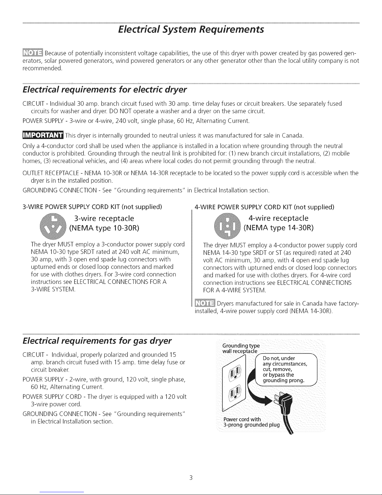
Do not, under "_
any circumstances,
cut, remove,
or bypassthe
,_grounding prong. _,
Powercord with
3-prong grounded plug
]
Page 4

Gas supply requirements
- EXPLOSION HAZARD - Uncoated copper
tubing will corrode when subjected to natural gas, causing
gas leaks. Use ONLY black iron, stainless steel, or plastic-coat-
ed brass piping for gas supply.
1. Installation MUST conform with local codes, or in the
absence of local codes, with the National Fuel Gas Code,
ANSI Z223.1 (latest edition).
2. The gas supply line should be 1/2 inch (1.27 cm) pipe.
3. If codes allow, flexible metal tubing may be used to
connect your dryer to the gas supply line. The tubing
MUST be constructed of stainless steel or plastic-coated
brass.
4. The gas supply line MUST have an individual shutoff valve.
Exhaust system requirements
Use only 4 inch (10.2 cm) diameter (minimum) rigid or flexible
metal duct and approved vent hood which has a swing-out
damper(s) that open when the dryer is in operation. When
the dryer stops, the dampers automatically closeto prevent
drafts and the entrance of insects and rodents. Toavoid
restricting the outlet, maintain a minimum of 12 inches (30.5
cm) clearance between the vent hood and the ground or any
other obstruction.
5. A 1/8 inch (0.32 cm) N.RT.plugged tapping, accessible
for test gauge connection, MUST be installed immediately
upstream of the gas supply connection to the dryer.
6. The dryer MUST be disconnected from the gas supply
piping system during any pressure testing of the gas
supply piping system at test pressures in excess of 1/2 psig
(3.45 kPa).
7. The dryer MUST be isolated from the gas supply piping
system during any pressure testing of the gas supply
piping system at test pressures equal to or lessthan 1/2
psig (3.45 kPa).
8. Connections for the gas supply must comply with the
Standard for Connectors for Gas Appliances, ANSI Z21.24.
- FIRE HAZARD - Failure to follow these in-
structions can create excessive drying times and fire hazards.
The following are specific requirements for
proper and safe operation of your dryer.
- FIRE HAZARD - Do not install a clothes
dryer with flexible plastic or metal foil venting materials.
Flexible venting materials are known to collapse, be easily
crushed and trap lint. These conditions will obstruct clothes
dryer airflow and increase the riskof fire.
If your present system is made up of plastic duct or metal foil
duct, replace it with a rigid or semi-rigid metal duct. Also,
ensure the present duct isfree of any lint prior to installing
dryer duct.
Correct
ii
Correct
'1i
Incorrect
'1ii
Incorrect
Page 5

Exhaust system requirements, continued
- FIRE HAZARD - A clothes dryer must be
exhausted outdoors. Do not exhaust dryer into a chimney, a
wall, a ceiling, an attic, a crawl space or any concealed space
of a building. A clothes dryer produces combustible lint. If
the dryer is not exhausted outdoors, some fine lint will be
expelled into the laundry area. An accumulation of lint in any
area of the home can create a health and fire hazard.
The dryer must be connected to an exhaust outdoors.
Regularly inspect the outdoor exhaust opening and remove
any accumulation of lint around the outdoor exhaust opening
and in the surrounding area.
- FIRE HAZARD -
• Do not allow combustible materials (for example: clothing,
draperies/curtains, paper) to come in contact with exhaust
system. The dryer MUST NOT be exhausted into a chim-
ney, a wall, a ceiling, or any concealed space of a building
which can accumulate lint, resulting in afire hazard.
Do not screen the exhaust ends of the vent system, or use
any screws, rivets or other fasteners that extend into the
duct to assemble the exhaust system. Lint can become
caught in the screen, on the screws or rivets, clogging the
duct work and creating a fire hazard aswell as increasing
drying times. Use an approved vent hood to terminate
the duct outdoors, and sealall joints with metal foil tape.
All male duct pipe fittings MUST be installed downstream
with the flow of air.
- FIRE HAZARD - Exceeding the length of
duct pipe or number of elbows allowed in the "MAXIMUM
LENGTH" charts can cause an accumulation of lint in the ex-
haust system. Plugging the system could create a fire hazard,
as well as increase drying times.
MAXIMUM LENGTH
of 4" (10.2cm) Rigid Metal Duct
VENT HOOD TYPE
o
o_
0
1
2
3
4
o
(lO.2cm)
(Preferred)
4"
64 ft. (19.5 m)
52 ft. (15.9 m)
44 ft. (13.5 m)
32 ft. (9.8 m)
28 ft. (9.5 m)
Iouvered
2.5"
(6.35cm)
48 ft. (14.6 m)
40 ft. (12.2 m)
32 ft. (9.8 m)
24 ft. (7.3 m)
16 ft. (4.9 m)
- FIRE HAZARD -
Do not install flexible plastic or flexible foil venting mate-
rial.
If installing semi-rigid venting, do not exceed 8 ft. (2.4 m)
duct length.
Install male fittings in correct direction:
CORRECT INCORRECT
Page 6
Exhaust system requirements, continued
In installations where the exhaust system is not described in
the charts, the following method must be used to determine
if the exhaust system is acceptable:
1. Connect an inclined or digital manometer between the
dryer and the point the exhaust connects to the dryer.
2. Set the dryer timer and temperature to air fluff (cool
down) and start the dryer.
3. Readthe measurement on the manometer.
4. The system back pressure MUST NOT be higher than
0.75 inches of water column. If the system back pressure
is lessthan 0.75 inches of water column, the system is
acceptable. If the manometer reading is higher than .075
inches of water column, the system istoo restrictive and
the installation is unacceptable.
Although vertical orientation of the exhaust system is
acceptable, certain extenuating circumstances could affect
the performance of the dryer:
• Only the rigid metal duct work should be used.
Venting vertically through a roof may expose the exhaust
system to down drafts causing an increase in vent
restriction.
Running the exhaust system through an uninsulated area
may cause condensation and faster accumulation of lint.
Compression or crimping of the exhaust system will cause
an increase in vent restriction.
The exhaust system should be inspected and cleaned a
minimum of every 18 months with normal usage. The
more the dryer is used, the more often you should check
the exhaust system and vent hood for proper operation.
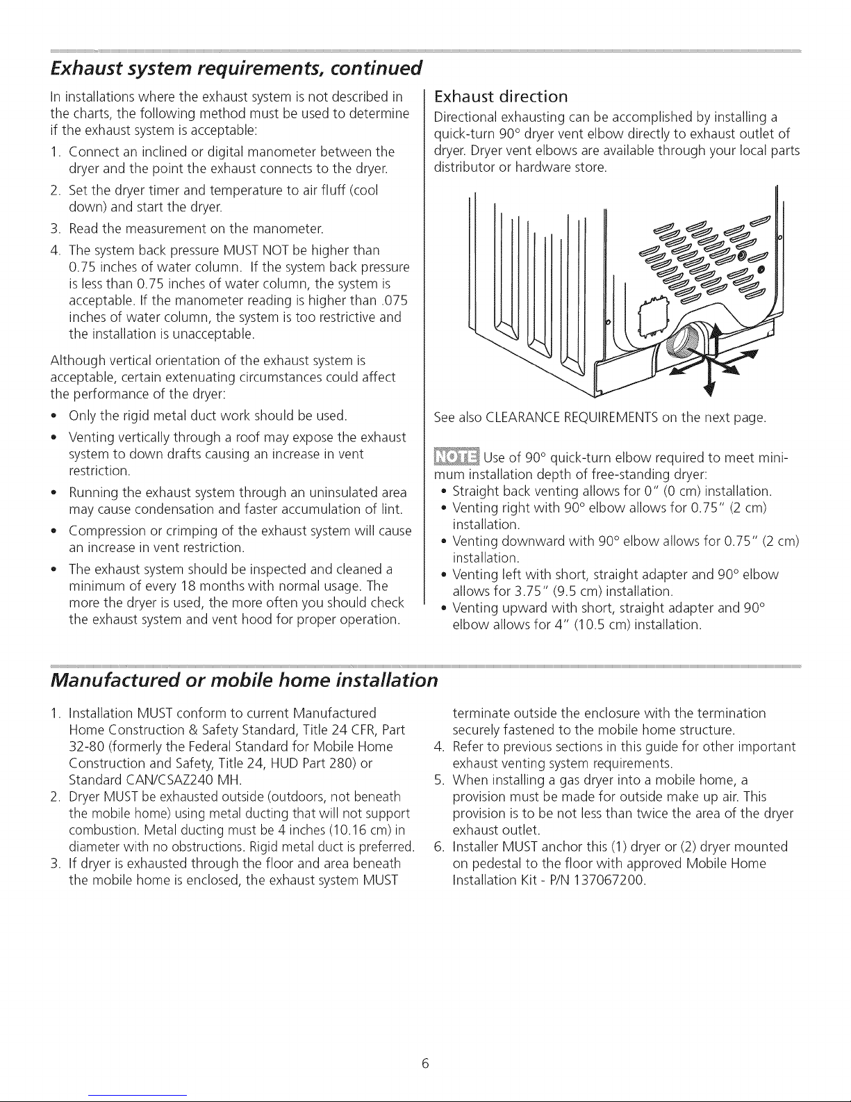
Exhaust direction
Directional exhausting can be accomplished by installing a
quick-turn 90° dryer vent elbow directly to exhaust outlet of
dryer. Dryer vent elbows are available through your local parts
distributor or hardware store.
See also CLEARANCE REQUIREMENTSon the next page.
Use of 90° quick-turn elbow required to meet mini-
mum installation depth of free-standing dryer:
Straight back venting allows for 0" (0 cm) installation.
Venting right with 90° elbow allows for 0.75" (2 cm)
installation.
Venting downward with 90° elbow allows for 0.75" (2 cm)
installation.
Venting left with short, straight adapter and 90° elbow
allows for 3.75" (9.5 cm) installation.
Venting upward with short, straight adapter and 90°
elbow allows for 4" (10.5 cm) installation.
Manufactured or mobile home installation
1. Installation MUST conform to current Manufactured
Home Construction & Safety Standard, Title 24 CFR, Part
32-80 (formerly the Federal Standard for Mobile Home
Construction and Safety, Title 24, HUD Part 280) or
Standard CAN/CSAZ240 MH.
2. Dryer MUSTbe exhausted outside (outdoors, not beneath
the mobile home) using metal ducting that will not support
combustion. Metal ducting must be 4 inches (10.16 cm)in
diameter with no obstructions. Rigid metal duct is preferred.
3. If dryer isexhausted through the floor and area beneath
the mobile home is enclosed, the exhaust system MUST
terminate outside the enclosure with the termination
securely fastened to the mobile home structure.
4. Refer to previous sections in this guide for other important
exhaust venting system requirements.
5. When installing a gas dryer into a mobile home, a
provision must be made for outside make up air. This
provision isto be not lessthan twice the area of the dryer
exhaust outlet.
6. Installer MUST anchor this (1) dryer or (2) dryer mounted
on pedestal to the floor with approved Mobile Home
Installation Kit- P/N 137067200.
Page 7

Clearance requirements
- EXPLOSION HAZARD - Do not install the
dryer where gasoline or other flammables are kept or stored.
If the dryer is installed in a garage, it must be a minimum
of 18 inches (45.7 cm) above the floor. Failure to do so can
result in death, explosion, fire or burns.
DO NOT INSTALL YOUR DRYER:
1. In an area exposed to dripping water or outside weather
conditions.
2. In an area where it will come in contact with curtains,
drapes, or anything that will obstruct the flow of com-
bustion and ventilation air.
3. On carpet. Floor MUST be solid with a maximum slope of
1 inch (2.54 cm).
INSTALLATION IN A RECESS OR CLOSET
1. A dryer installed in a bedroom, bathroom, recessor closet,
MUST be exhausted outdoors.
2. No other fuel burning appliance shall be installed in the
same closet asthe gas dryer.
3. Your dryer needs the space around it for proper
ventilation.
DO NOT install your dryer in a closet with a solid door.
4. Closet door ventilation required: A minimum of 120
square inches (774.2 cm2)of opening, equally divided at
the top and bottom of the door, is required. Openings
should be located 3 inches (7.6 cm) from bottom and top
of door. Openings are required to be unobstructed when
a door is installed. A Iouvered door with equivalent air
openings for the full length of the door is acceptable.
MINIMUM INSTALLATIONCLEARANCES -Inches (cm)
SIDES REAR TOP FRONT
Alcove 0" (0 cm) 0" (0 cm)* 0" (0 cm) n/a
Under-
Counter
Closet 0" (0 cm) 0" (0 cm)* 0" (0 cm) 1" (2.5 cm)
* For other than straight back venting, a quick-turn 90°
dryer vent elbow (vented right or down in free-standing
dryer or right on pedestal-mounted dryer) must be
installed to achieve 0" (0 cm)installation.
0" (0 cm) 0" (0 cm)* 0" (0 cm) 1" (2.5 cm)
ii
ii
0" -----I1_ _---
(0cm) _ I
_L
0
! t
!
ii ii
ii H
1" --"!l_h _--" 0" _"'€_ m "_'-_
(2.54cm) i _ (Ocm) ii
closet door
i
To achieve an installation with 0" (0 cm) clearance
for the back of the dryer (for other than straight back vent-
ing), a quick-turn 90° dryer vent elbow must be installed as
described previously in this manual.
Page 8

Installed dryer dimensions
._=== 48.25" (122.5cm)'
to clear open door
freestand dryer
on floor
.......... fLo_r=l_ = = =
30.5" (77,5cm)* _-
to front of dosed door
51,25"
(130cm)
36.0"
(91.5cm)
gas supply
pipe on rear
of gas unit
27.0"
(68.5cm)
0
electrical
supply on
rear of unit
c_'_enterline
height for
rear vent
dryer mounted on
optional pedestal
* To obtain these minimal depth dimensions, dryer must be vented straight back.
Using a quick-turn 90 ° elbow (right or down on freestanding dryer) adds approximately
0.75 in. (2.0 cm) to instanation depth. Upward venting of exhaust on pedestal-mounted
or freestanding dryer adds approximately 4 in. (10.2 cm) to installation depth. Leftward
venting on pedestal-mounted or freestanding dryer adds approximately 3.75 in. (9.5 cm)
to installation depth. Downward venting of exhaust on pedestal-mounted dryer adds
approximately 2.25 in. (5.7 cm) to installation depth.
_,_===48.25" (122.5cm)'
to clear open door
f 6.9"
(43cm)
3.75"_ _l====
(9.5cm) _==== 13.50"_
gas supply
pipe on
of gas unit
(34.5cm)
to center of rear vent
27,0'
(68.5cm)
0
19.0"
(48cm)
electrical
supply on
rear of unit
centerline
height for
rear vent
* To obtain these minimal depth dimensions, dryer must be vented straight back. Using a quick-turn 90 ° elbow (right) adds approximately 0.75 in. (2 cm) to
installation depth. Upward venting of exhaust on stacked dryer adds approximately 4 in. (40.2 cm) to installation depth. Downward venting of exhaust on
stacked dryer adds approximately 2.25 in. (6.5 cm) to installation depth. Leftward venting of exhaust on stacked dryer adds approximately 3.75 in. (9.5 cm) to
installation depth.
0
l
39"
(99cm)
Page 9

Electrical installation
The following are specific requirements for proper and safe
electrical installation of your dryer. Failure to follow these
instructions can create electrical shock and/or a fire hazard.
- ELECTRICAL SHOCK HAZARD -
• This appliance MUST be properly grounded. Electrical
shock can result if the dryer is not properly grounded.
Follow the instructions in this manual for proper ground-
ing.
Do not use an extension cord with this dryer. Some ex-
tension cords are not designed to withstand the amounts
of electrical current this dryer utilizes and can melt, creat-
ing electrical shock and/or fire hazard. Locate the dryer
within reach of the receptacle for the length power cord
to be purchased, allowing some slack in the cord. Refer
to the pre-installation requirements in this manual for the
proper power cord to be purchased.
longer drying times than dryers operating on 240 volt power
supply.
Grounding requirements - Electric dryer (USA)
- ELECTRICAL SHOCK HAZARD - Improper
connection of the equipment grounding conductor can result
in a risk of electrical shock. Check with a licensed electrician
if you are in doubt asto whether the appliance isproperly
grounded.
For a grounded, cord-connected dryer:
1. The dryer MUST be grounded. In the event of a
malfunction or breakdown, grounding will reduce the
risk of electrical shock by a path of least resistance for
electrical current.
2. After you purchase and install a 3 wire or 4 wire power
supply cord having an equipment-grounding conductor
and a grounding plug that matches you wiring system,
3. DO NOT modify the plug you've installed on this
For a permanently connected dryer:
1. The dryer MUST be connected to a grounded metal,
- ELECTRICAL SHOCK HAZARD -
A U.L.-approved strain relief must be installed onto pow-
er cord. If the strain relief is not attached, the cord can be
pulled out of the dryer and can be cut by any movement
of the cord, resulting in electrical shock.
Do not use an aluminum wired receptacle with a copper
wired power cord and plug (or vice versa). A chemical
reaction occurs between copper and aluminum and can
cause electrical shorts. The proper wiring and receptacle
is a copper wired power cord with a copper wired recep-
tacle.
Dryers operating on 208 volt power supply will have
the plug MUST be plugged into an appropriate, copper
wired receptacle that is properly installed and grounded
in accordance with all local codes and ordinances. If in
doubt, call a licensed electrician.
appliance. If it will not fit the outlet, have a proper outlet
installed by a qualified electrician.
permanent wiring system; or an equipment grounding
conductor must be run with the circuit conductors and
connected to the equipment-grounding terminal or lead
on the appliance.
Grounding requirements - Electric dryer (Canada)
- ELECTRICAL SHOCK HAZARD - Improper
connection of the equipment grounding conductor can result
in a risk of electrical shock. Check with a licensed electrician
if you are in doubt asto whether the appliance isproperly
grounded.
For a grounded, cord-connected dryer:
1. The dryer MUST be grounded. In the event of a
malfunction or breakdown, grounding will reduce the
risk of electrical shock by a path of least resistance for
electrical current.
2. Since your dryer is equipped with a power supply
cord having an equipment-grounding conductor and
a grounding plug, the plug must be plugged into an
appropriate outlet that is properly installed and grounded
in accordance with all local codes and ordinances. If in
doubt, call a licensed electrician.
3. DO NOT modify the plug provided with this appliance. If
it will not fit the outlet, have a proper outlet installed by a
qualified electrician.
Page 10
1.Thedryerisequippedwithathree-prong(grounding)plug
foryourprotectionagainstshockhazardandshouldbe
pluggeddirectlyintoaproperlygroundedthree-prong
receptacle.
2. Theplugmustbepluggedintoanappropriateoutletthat
isproperlyinstalledandgroundedinaccordancewithall
localcodesandordinances.Ifindoubt,callalicensed
electrician.
3. DONOTmodifytheplugprovidedwiththisappliance.If
itwillnotfit theoutlet,haveaproperoutletinstalledbya
qualifiedelectrician.
Gas connection
Grounding type
wall receptacle
Do not, under
any circumstances,
cut, remove,
or bypass the
grounding prong,
Powercord with
3-prong grounded plug
,J
"X
/
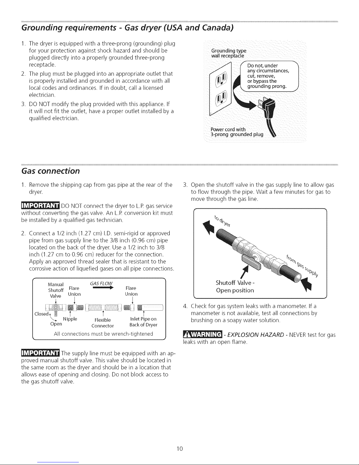
1. Remove the shipping cap from gas pipe at the rear of the
dryer.
DO NOT connect the dryer to L.R gas service
without converting the gas valve. An L.R conversion kit must
be installed by a qualified gas technician.
2. Connect a 1/2 inch (1.27 cm) I.D. semi-rigid or approved
pipe from gas supply line to the 3/8 inch (0.96 cm) pipe
located on the back of the dryer. Use a 1/2 inch to 3/8
inch (1.27 cm to 0.96 cm) reducer for the connection.
Apply an approved thread sealer that is resistant to the
corrosive action of liquefied gases on all pipe connections.
Manual GASFLOW
Shutoff Flare _ Flare
Valve Union Union
; 1 1
--los R Nipple Flexible Inlet Plpeon
Open Connector Back of Dryer
All connections must be wrench-tightened
The supply line must be equipped with an ap-
proved manual shutoff valve. This valve should be located in
the same room as the dryer and should be in a location that
allows easeof opening and closing. Do not block accessto
the gas shutoff valve.
3. Open the shutoff valve in the gas supply line to allow gas
to flow through the pipe. Wait a few minutes for gas to
move through the gas line.
Shutoff Valve-
Open position
4. Check for gas system leaks with a manometer. If a
manometer is not available, test all connections by
brushing on a soapy water solution.
- EXPLOSION HAZARD - NEVERtest for gas
leaks with an open flame.
10
Page 11

3-wire receptacle
(NEMA type 10-30R)
- ELECTRICAL SHOCK HAZARD - Failure
to disconnect power source before servicing could result in
personal injury or even death.
1. Turn off power supply to outlet.
2. Remove the screw securing the terminal block access
cover in the lower corner on the back of the dryer.
,
Install a UL-approved strain relief according to the power
cord/strain relief manufacturer's instructions in the power
cord entry hole below the accesspanel. At this time, the
strain relief should be loosely in place.
4. Thread an UNPLUGGED,UL-approved, 30 amp. power
cord, NEMA 10-30 type SRDT,through the strain relief.
5. Attach the power cord neutral (center wire) conductor to
the SILVERcolored center terminal on the terminal block.
Tighten the screw securely.
6. Attach the remaining two power cord outer conductors
to the outer, BRASScolored terminals on the terminal
block. Tighten both screws securely.
_ _ Access cover
screw
Terminal
_S ____ block
_______f (BRASS terminal)
___ (BRASS terminal)
........... UL-approved
.................. _// strain relief here
___ Install
Line 2
Neutral
Internal ground
(GREENscrew)
Terminal screw
recovery slot
- ELECTRICAL SHOCK HAZARD - Do not
make a sharp bend or crimp wiring/conductor at connections.
7. Follow manufacturer's guidelines for firmly securing the
strain relief and power cord.
8. Reinstall the terminal block cover.
If moving dryer from a 4-wire system and
installing it in a 3-wire system, move the internal ground from
the center terminal back to the GREENscrew next to the
terminal block.
If a terminal screw falls during cord installation, it
can be retrieved in the terminal screw recovery slot below the
access panel.
DO NOT remove
internal ground in
a 3-wire system!!
Neutral
terminal
11
Page 12

Electrical connection (non-Canada) - 4 wire cord
4-wire receptacle
(NEMA type 14-30R)
- ELECTRICAL SHOCK HAZARD - Failure
to disconnect power source before servicing could result in
personal injury or even death.
-- Neutral
',WHITEwire)
1. Turn off power supply to outlet.
2. Remove the screw securing the terminal block access
cover in the lower corner on the back of the dryer.
3. Install a UL-approved strain relief according to the power
cord/strain relief manufacturer's instructions in the power
cord entry hole below the accesspanel. At this time, the
strain relief should be loosely in place.
4. Thread an UNPLUGGED,UL-approved, 30 amp. power
cord, NEMA 14-30 type ST or SRDT,through the strain
relief.
5. Disconnect the internal (BLACK) dryer harness ground
wire from the (GREEN)ground screw next to the terminal
block.
6. Attach the ground (GREEN)power cord wire to the
cabinet with the ground (GREEN)screw. Tighten the
screw securely.
7. Move the internal dryer harness ground (BLACK) wire to
the terminal block and attach it along with the neutral
(WHITE) power cord wire conductor to the center, SILVER
colored terminal on the terminal block. Tighten the screw
securely.
8. Attach the REDand BLACK power cord conductors to
the outer, BRASScolored terminals on the terminal block.
Tighten both screws securely.
- ELECTRICAL SHOCK HAZARD - Do not
make a sharp bend or crimp wiring/conductor at connections.
9. Follow manufacturer's guidelines for firmly securing the
strain relief and power cord.
10. Reinstall the terminal block cover.
Access cover
screw
block
Line 2
(BRASSterminal)
Neutral
(SILVERterminal)
Line 1
(BRASSterminal)
Internal ground
(GREENscrew)
............ UL-approved
____ Install
strain relief here
Terminal screw
recovery slot
If a terminal screw falls during cord installation, it
can be retrieved in the terminal screw recovery slot below the
access panel.
Move internal ground (BLACK)
neutral (SILVER)
wire to for 4-wire system. "_h
terminal
/
"\\\
GREEN
|
Neutral
terminal
WHITE
neutral wire
ground screw
12
GREEN
ground wir,
RED power wir
BLACK
or RED
power wire
BLACK or
Page 13

General installation
.
Connect the exhaust duct to the outside exhaust system
(see pages 4 through 6). Use of a 4" (10.2 cm) clamp (item
A) isrecommended to connect the dryer to the exhaust
vent system. Use metal foil tape to seal all other joints.
.
Carefully slide the dryer to itsfinal position. Adjust one or
more of the legs until the dryer is resting solidly on all four
legs. Place a level on top of the dryer. The dryer MUST be
level and resting solidly on all four legs. Rock alternating
corners to check for stability. Remove and discard door
tape.
Be sure the power isoff at a circuit breaker/
fuse box before plugging the power cord into an outlet.
3. Plug the power cord into a grounded outlet.
4. Turn on the power at the circuit breaker/fuse box.
5. Readthe Use & Care Guide provided with the dryer. It
contains valuable and helpful information that will save
you time and money.
6. If you have any questions during initial operation, please
review the "Avoid Service Checklist" in your Use & Care
Guide before calling for service.
7. Placethese instructions in a location near the dryer for
future reference.
A wiring diagram and technical data sheet are
located inside the dryer console,
wall rece
any circumstances,
Power coid with
3-prong grounded p!ug
13
Page 14

Window Door Reversal Instructions
Figure 1
I Opel_ door an/: remc._,e four (4) pigs n tho door open ng
op_si_ the, hinges Re_in all pa_r_sfor uses_teL _il_ess
otherwise no_d {Figure 1) Note: Use care irt r_rllo_:ing p!ugs
ir_not _r_ing p_[_t on _le front par_e_
Figure 2
Eigure 4
5 Remo,*_, two (2) door handl® scr vzs and t,'/o (2) hok, p_ugs
ff,,n door Ag;H_ takng ,:are i_t ,*o 5 _al(_ paint on d,_r
(F gu_e 4)
2 6egn remodng fhe Ic,_r (4} S _,,'_sfl_at at't_ct the Inge to
111efront panel¸ {Figure 2} For _st _esuits_ st,_tt _ only
removi_ng on_ scr_,_vper hin_ Then onIv/oo_n th_ two
tem_fr_i_ screw':, _ile _rmly ho_dir_g doo_ _ [4_evel_t _ge
hinge_ front Fan_ o_ d_or A_r the rem_iniE_g _re_,s a_e
_oosened, con_r_ue to remove all
Figure 3
Figur_ 5
6 PuI_ handle _way fort dOOr a%embey {Figure 5}
7 Sepa ate the O_r doe from the i!ne d(_> assembly vv't_
a pu_ Rni_ o_flat screw ddw_ _igur_ @
3 Pla_e dae_ on a lowd or pad (andle de do_ls to pmuent
_ny _ssib_÷ _t_h÷_ _ doo_ Remove all rem_i_J//g _o_ (_
_r_ws betw_n h_ng_ _nd door¸ (Fi_ur_ 3)
4 _move _/_ ¸{4) screws from _d÷ of door _po_i_ _f _he_÷
hinge _'v_smounted
Page 15

Figure 7
8. Remove lens locating screw. (Figure 7)
11. Reassemble lens to transition ring with holes to install
handle on right-hand side of door assembly. For proper fit
insure the retention tabs on transition ring are on top of lens
Figure 11
12. Reassembly outer door to inner door assembly. (Figure 11)
13. Install four (4) screws securing hinge to door assembly in
the new location, take note to place hinge in correct
orientation.
14. Install four (4) screws into holes that had secured the
hinge.
15. Remove striker and discard.
Figure 8
9. Disengaging several of the retention tabs and pull lens away
from the transition ring. (Figure 8)
Figure 9
16. Remove square plug and reinstall in hole striker was just
removed.
17. Install striker (included in literature bag) into hole square
plug was previously installed.
Figure 12
18. Reinstall door handle by placing the handle mounting
bossesthrough holes in lens and transition ring and installing
screws through inner door and tighten into handle bosses.
(Figure 12).
Figure 10
10. Remove two (2) transition ring plugs and reinstall on
previous handle side. (Figures 9 and 1O)
19. Grasping firmly the top of the door, position the door near
the door opening and align the top hinge hole to the top hole
in the front panel door opening. Once the first screw is started,
attach the second screw to the lower hinge. Once both screws
are tightened, instal{ the remaining two screws.
20. Install four (4) plugs into the front panel door opening
where hinges were originally installed.
15
Page 16

Accessories
MATCHING STORAGE PEDESTAL*
White Pedestal-P/NNLPWD15or 48062
BlackPedestal- P/NNLPWD15Eor 48066
SilverPedestal- P/NNLPWD15Aor 46267
*Other colors may be available. Contact the source where you purchased
your dryer.
A storage pedestal accessory, specifically designed for this
dryer may be used to elevate the dryer for easeof use. This
pedestal will add about 15" (38 cm) to the height of your
unit for a total height of 51.25" (130 cm).
DRYER STACKING KIT
P/N134700600
Depending on the model you purchased, a kit for stacking
this dryer on top of matching washer may have been
included in the initial purchase of your dryer. If your model
did not include a stacking kit or you desire another stacking
kit, you may order one
LP CONVERSION KIT
P/NPCK4200
Gas dryers intended for use in a location supplied with LP
must use a conversion kit prior to installation.
MOBILE HOME INSTALLATION KIT
P/N137067200
Installations in mobile homes require use of MOBILE HOME
INSTALLATIONKIT.
Failureto use accessoriesmanufactured by (or
approved by) the manufacturer could result in personal injury,
property damage or damage to the dryer.
7_00',
'S,00,,
DRYING RACK
P/N137067300
Depending on the model you purchased, a drying rack may
have been included in the initial purchase of your dryer.
If your model did not include a drying rack or you desire
another drying rack, you may order one.
UNIVERSAL APPLIANCE WRENCH
P/N137019200
A UNIVERSALAPPLIANCEWRENCH is available to aid in
dryer/washer/pedestal feet adjustment.
TOUCH UP PAINT PENS*
White TouchUpPen- P/N5303321319
BlackTouchUp Pen- P/N5304458932
SilverTouchUp Pen- P/N5304471228
*Other colors may be available. Contact the source where you purchased
your dryer.
Replacement parts:
If replacements parts are needed for your washer, contact the _ - ELECTRICAL SHOCK HAZARD - Label all
source where you purchased your dryer, wires prior to disconnection when servicing controls. Wiring
errors can cause improper and dangerous operation. Verify
proper operation after servicing.
16
Page 17

lndice
Instrucciones importantes de seguridad ............................... 17
Requisitos de preinstalacion ................................................ 17
Requisitos de instalacion ............................................... 18-22
Dimensiones de la lavadora instalada .................................. 23
Instrucciones de instalacion ........................................... 24-28
Inversion de la puerta .................................................... 29-30
Accesorios/Piezas de repuesto ............................................. 31
lnstrucciones importantes de seguridad
Parasu seguridad, debe seguir la informacion de esta guia para minimizar el riesgo de incendio o
explosion o para evitar da_os a la propiedad, lesiones personales o incluso la muerte. No almacene ni utilice gasolina ni otros
liquidos o vapores inflamables cerca de este o de cualquier otto electrodomestico.
Identificaci6n de los simbolos, palabras y avisos de
seguridad
Lasindicaciones de seguridad incluidas en este manual
aparecen precedidas de un aviso titulado "ADVERTENCIA" o
"PRECAUCION", de acuerdo con el nivel de riesgo.
- PELIGRODEINCENDIO - Lea lassiguientes instrucciones antes de instalar y utilizar este electrodomestico:
• Despuesde desembalar la secadora, destruya los cartones y lasbolsas de pl_istico. Los ni_os podrian utilizarlos para jugar. Los
cartones cubiertos con alfombras, cubrecamas, o I_iminasde pl_istico pueden convertirse en c_imarasde aire hermeticamente
cerradas y provocar asfixia. Coloque todos los materiales en un basurero o mantengalos fuera del alcance de los ni_os.
• La instalacion y el servicio de la secadora de ropa deben set Ilevados a cabo pot un instalador calificado, agencia de servi-
cios o proveedor de gas.
• Instale la secadora de ropa de acuerdo con las instrucciones del fabricante y los codigos locales.
• La reparacion electrica de la secadora debe cumplir con los codigos y las ordenanzas locales y la ultima edicion del Codigo
Electrico Nacional (National Electrical Code), el ANSI/NFPA70, o bien en Canada1,el CSA C22.1 del Codigo Electrico de
Canada1(Canadian Electrical Code) Parte 1.
• El servicio de gas de la secadora debe cumplir con los codigos y las ordenanzas locales, y la ultima edicion del Codigo de
Gas Nacional (National Fuel GasCode), el ANSI Z223.1, o bien en Canada1,el CAN/CGA B149,1-2000.
• La secadora se dise_0 conforme a los codigos ANSI Z 21.5.1 o ANSI/UL 2158 - CAN/CSA C22.2 N.° 112 (ultimas edicio-
nes) solo para USO DOMESTICO. No se recomienda esta secadora para uso comercial, como pot ejemplo, en restaurantes,
salones de belleza, etc.
• No utilice materiales de ventilacion de pl_istico ni de papel de aluminio flexibles para instalar la secadora de ropa. Pot Io
general, dichos materiales se desarman, se deterioran con facilidad y acumulan pelusa. Estascondiciones obstruyen el
flujo de aire de la secadora y aumentan el riesgo de incendio.
• Lasinstrucciones de esta guia y todo el material que se incluye con esta secadora no tienen como proposito cubrir todas
las condiciones y situaciones que puedan presentarse. Cuando instale, opere o repare cualquier artefacto DEBEtenet cui-
dado y hacer uso de buenas pr_icticas de seguridad.
QUI _ HACER SI SIENTE OLOR A GAS:
No intente encender ning0n electrodomestJco.
No toque ning0n interruptor electrico; no utilice ning0n telefono en la vivienda.
Despeje la habitacion, el edificio o el _ireade todos los ocupantes.
Llame inmediatamente a su proveedor de gas desde el telefono de un vecino. Siga lasinstrucciones del proveedor de gas.
Si no puede ponerse en contacto con el proveedor de gas, Ilame a los bomberos.
_Este simbolo le advierte sobre
situaciones que pueden causar lesiones personales graves, la
muerte o da_os materiales.
_Este simbolo le advierte sobre situacio-
nes que pueden causar lesionespersonales o da_os materiales.
Conserve estas instrucdones para referenda futura.
Requisitos de preinstalacion
Herramientas y materiales necesarios para la instalaci6n:
• Pinzas ajustables
• Destornilladores Philips con punta
derecha y cuadrada
• Llave ajustable
• Llave para tubos de suministro de gas
• Cinta aislante resistente al gas LP
(para suministro de gas natural o LP)
• Nivel de carpintero
• Capucha de ventilacion externa
• Conducto de escape de metal rigido
o semirigido de 4 pulgadas (10 cm)
• Kit de cablesde alimentaciOntrifilar o te-
trafilar de 240 voltios (secadoraelectrica)
• Abrazadera de 4" (10,2 cm)
17
• V_ilvulade cierre de linea de gas (se-
cadora a gas)
Adaptadores NPIde uni6n acampana-
da (x2) y linea flexible de suministro de
gas (secadora a gas) de 1/2'(15,2 cm)
Cinta de papel aluminio (no cinta
adhesiva aislante)
Page 18

Requisitos de! sistema electrico
_: Debido a posibles variaciones en el voltaje, no se recomienda utilizar esta secadora con electricidad generada a
partir de generadores a gas, solares, eolicos nide ninguna otra clase que no sean los empleados pot su empresa de electri-
cidad local.
Requisitos electricos de la secadora electrica:
CIRCUITO: circuito independiente individual de 30 amp. con fusibles de acci0n retardada o disyuntores. Use circuitos con
fusibles separados para la lavadora y la secadora. NO haga funcionar una lavadora y una secadora en el mismo circuito.
SUMINISTROELECTRICO:trifilar o tetrafilar, 240 V, 1 fase, 60 Hz, corriente alterna.
A menos que hayasidofabricada para {aventa en Canada1,estasecadoraest,1conectadaa tierra internamente a
travesde un enlacea un conductor neutro.
SOIodebe usar un cordon tetrafilar cuando el electrodomestico se instale en un lugar donde se prohiba la puesta a tierra a
traves de{ conductor neutro. Laconexi0n a tierra a traves de{neutro est,1prohibida para:(1) instalacionesde circuitos de bifurcaci0n
nuevos;(2) casasrodantes; (3)vehiculosrecreativos;y (4)_ireascuyasleyeslocalesno permiten la puestaa tierra atravesdel neutro.
RECEPTACULODELTOMACORRIENTE- recept_iculo NEMA 10-30 R o NEMA 14-30 Rque debe estar ubicado en un lugar al
que pueda acceder el cable de alimentaci0n electrica cuando la secadora este instalada.
CONEXION A TIERRA:consulte "Requisitos de conexi0n a tierra" en la secci0n {nstalaci0n electrica.
CABLE DE ALIMENTACION ELECTRICATRIFILAR (no
incluido)
Receptaculo trifilar
(tipo NEMA 10-30R)
La secadora DEBEemplear un cable de alimentacion
electrica de 3 conductores tipo NEMA 10-30, SRDT
calificado para CA minima de 240 voltios, 30 amp., con 3
conectores de terminal horquilla con extremos doblados
hacia arriba o de bucle cerrado y calificados para uso en
secadoras de ropa. Paraobtener instrucciones sobre {a
conexion trifilar, consulte CONEXIONESELECTRICASPARA
UN SISTEMATRIFILAR.
Requisitos electricos de la secadora a gas:
CIRCUITO- Circuito individual de bifurcaci6n de 15 amp.,
correctamente polarizado y con conexi6n a tierra con fusible
de retardo de 15 amp. o con interruptor autom_itico.
SUMINISTROELECTRICO:corriente alterna de 2 cables, con
conexion a tierra, 120 voltios, monof_isica, 60 Hz.
CABLEDEALIMENTACION ELECTRICA:la secadora est,1
equipada con un cable de alimentacion trifilar de 120 voltios.
CONEXION A TIERRA:consulte "Requisitos de conexion a tierra"
en la secci0n Instalaci0n electrica.
CABLE DE ALIMENTAClON ELECTRICATETRAFILAR (no
incluido)
Receptaculo tetrafilar
(tipo NEMA 14-30R)
La secadora DEBEemplear un cable de alimentacion
electrica de 4 conductores tipo NEMA 14-30, SRDTo
ST(segun se especifique) calificado para CA minima
de 240 voltios, 30 amp., con 4 conectores de terminal
horquilla con extremos doblados hacia arriba o de bucle
cerrado y calificados para uso en secadoras de ropa.
Para obtener instrucciones sobre {aconexion tetrafilar,
consulte CONEXIONESELECTRICASPARAUN SISTEMA
TETRAFILAR.
Lassecadoras fabricadas para la venta en Canada1vie-
nen con un cable de alimentacion electrica tetrafilar (NEMA
14-30R) de flibrica.
retire ni -")
deshabilite la clavija de{
conexi6n a tierra bajo {
ninguna circunstancia.j,/
con puesta a tie_
18
Page 19

Requerimientos del suministro de gas
- PELIGRO DE EXPLOSION - Lastube- 4.
rias de cobre sin recubrimiento se corroen al exponerse al gas
natural, Io que provoca perdiclas de gas. Utilice SOLAMENTE 5.
tuberias de hierro negro, acero inoxiclable o laton plastificaclo
para el suministro de gas.
1. Lainstalacion DEBErealizarsede acuerdo con loscodigos
localeso, en ausencia de ellos, con el Cocligo de Gas
Nacional (National Fuel Gas Code), ANSIZ223.1 (Oltima 6.
edicion).
2. La linea de suministro de gas clebe ser un tubo de 1,27 cm
(1/2 pulgada). 7.
3. Si los codigos Io permiten, se puecle utilizar un tubo de
metal flexible para conectar la secaclora a la linea de
suministro de gas. Latuberia DEBEser de acero inoxiclable 8.
o de laton plastificaclo.
Requisitos del sistema de escape
Utilice solo un conducto de metal flexible o rigido de 10,2
cm (4 pulgadas) de diametro (minimo) y una capucha de
ventilaci0n aprobada que tenga uno o mas reguladores de
tiro que se abran cuando {a secadora este en funcionamiento.
Cuando la secaclora se detiene, el regulador de tiro se
cierra automaticamente para evitar {a corriente de aire y el
ingreso de insectos y roeclores. Para evitar restringir {a salida
clel conducto, mantenga un espacio minimo de 30,5 cm
(12 pulgadas) entre la capucha de ventilaci0n y el suelo, o
cualquier otra obstrucci0n.
La {inea de suministro de gas DEBEtener una valvula de
cierre individual.
Se DEBEinstalar una clerivaci0n N.RT de 0,32 cm (1/8
puigadas) con tap0n roscaclo, que permita conectar
un meclidor de prueba, inmecliatamente clespues de
la conexi0n de suministro de gas a la secadora, en
contracorriente al flujo de gas.
La secadora DEBEestar clesconectada de {a tuberia de gas
durante cualquier prueba en la que la presi0n exceclalos
3,45 kPa (1/2 psig).
La secadora DEBEestar aislaclade la tuberia de gas
clurante cualquier prueba en la que la presi0n sea igual o
inferior a 3,45 kPa (1/2 psig).
Lasconexiones de{ suministro de gas cleben cumpiir con
la norma de conexiones de electroclomesticos a gas, ANSI
Z21.24.
f
- PELIGRO DE INCENDIO - El no
seguir estas instrucciones puecle producir tiempos de secado
excesivos y peligro de incendio.
Los siguientes son requisitos necesarios para el
funcionamiento seguro y correcto de su secadora.
- PELIGRO DE INCENDIO - No utilice
materiales de ventilaci0n de plastico ni de pape{ de aluminio
flexibies para instalar la secaclorade ropa. Pot Io general,
dichos materiales se clesarman, se deterioran con facilidad y
acumulan pelusa. Estasconcliciones obstruyen el flujo de aire
de la secadora y aumentan el riesgo de incendio.
Si su sistema actual est,1compuesto de un conclucto de
pbistico o papel de aluminio, reempbicelo por un conclucto
de metal rigiclo o semirigiclo. Aseg0rese de que el conclucto
existente no tenga pelusas antes de instalar el conclucto de la
secaclora.
iiiiiii iiiiiiiiiiiiiiiiiiiiiiiii!i_!_i_!_!_!_!_!_!_!_!_!_!_!_!_!_!_!_!_!_!_!_!_!_!_!_!_!_!_!_!_!_!_!_!_!_!_!_!_!_!_!_!_!_!_!_!_!_!_!_!_!_!_!_!_!_!_!_!_!_!_!_!_!_!_!_!_!_!_!_!_!_!_!_!_!_!_!_!_!_!_!_!_!_!_!_!_!_!_!_!_!_!_!_!_!_!_!_!_!_
Correcto
{ncorrecto
iii
Correcto
Incorrecto
19
Page 20

Requisitos del sistema de escape (continuaci6n)
- PELIGRO DE INCENDIO - Una seca-
dora de ropa debe tenet ventilaci0n a{ exterior. No ventile {a
secadora a una chimenea, pared, techo, _itico, pasajes entre
pisos ni ning0n espacio oculto de {avivienda. Lassecadoras
de ropa producen pelusa combustible. Si {asecadora no tiene
ventilaci0n a{ exterior, algunas pelusas finas se expulsar_in en
el _ireade lavanderia. La acumulaci0n de pelusa en cualquier
_ireade la vivienda puede constituir un peligro sanitario y un
riesgo de incendio.
La secadora debe estar conectada a un sistema de escape que
termine en el exterior de {avivienda. Inspeccione la abertura
de escape a{ exterior con frecuencia y elimine cualquier
acumulaci0n de pelusa en la abertura yen el _ireaque la
rodea.
- PELIGRO DE INCENDIO -
• No permita que materiales combustibles (pot ejemp{o:
ropa, tapiceria/cortinas, pape{) entrenen contacto con
el sistema de escape. La secadora NO DEBEtenet escape
a una chimenea, una pared, un techo ni ningun espacio
cerrado de un edificio que pueda acumular pelusa y cons-
tituir un peligro de incendio.
No bloquee los extremos de escape de{ sistema de ven-
tilaci0n, ni utilice tornillos, remaches ni otros sujetadores
que se extiendan hacia {a parte interna de{ conducto para
ensamblar{o. Esposible que {a pelusa quede atrapada en
el filtro, los tornillos o los remaches, Io que puede obstruir
la red de conductos y constituir un peligro de incendio,
asi como tambien aumentar los tiempos de secado. En
la salida de{ conducto al exterior, utilice una capucha de
ventilaci0n aprobada y selle todas {as uniones con cinta
de pape{ aluminio. Todos los accesorios macho para tubos
DEBENinstalarse teniendo en cuenta el flujo de aire.
- PELIGRO DE INCENDIO - Si se exce-
de la {ongitud de{ tubo del conducto o el numero de codos
permitidos en las tablas de "LONGITUD MAXIMA", se pue-
den acumular pelusas en el sistema de escape. La obstrucci6n
del sistema podria constituir un peligro de incendio, asi como
aumentar los tiempos de secado.
¢h
Conducto de metal rigido de 10,2 cm (4 pulgadas)
(recomendada)
LONGITUD MAXIMA
TIPO DECAPUCHA DE VENTILACION
S
u_
kO
oo
0 19.5 m (64 pies)
1 15.9 m (52 pies)
2 13.5 m (44 pies)
3 9.8 m (32 pies)
4 9.5 m (28 pies)
4" aberturas de
(10,2 cm) ventilacibn
2.5"
(6,35 cm)
14.6 m (48 pies)
12.2 m (40 pies)
9.8 m (32 pies)
7.3 m (24 pies)
4.9 m (16 pies)
- PELIGRO DE INCENDIO -
No utilice material de ventilacion flexible de pbistico o
aluminio.
Siva a instalar conductos de ventilaci0n semirrigidos, no
exceda una Iongitud de 8 pies (2,4 m).
Instale los accesorios macho en la direction
correcta:
CORRECTO INCORRECTO
20
Page 21

Requisitos del sistema de escape (continuacion)
En instalaciones en las que el sistema de escape no se
describa en las tablas, sedebe utilizar el siguiente metodo
para determinar si dicho sistema esaceptable:
1. Conecte un manometro inclinado o digital entre la
secadora y el punto donde el tubo de escape se conecta
con la secadora.
,
Coloque el temporizador y la temperatura de la secadora
en la opcion Air fluff - cool down (Esponjado con aire,
enfriamiento) y ponga en marcha la secadora.
,
Lea la medicion del manometro.
4.
La contrapresion del sistema NO DEBEser mayor que 2,5
cm (1 pulgada) de columna de agua. Si la contrapresion
del sistema esmenor que 2,5 cm (1 pulgada) de
columna de agua, el sistema esaceptable. Si la lectura
del manometro es mayor que 2,5 cm (1 pulgada) de
columna de agua, el sistema esdemasiado restrictivo y la
instalacion es inaceptable.
Si bien la orientacion vertical del sistema de escape es
aceptable, ciertas circunstancias atenuantes podrian afectar el
funcionamiento de la secadora:
• Solo sedebe utilizar una red de conductos de metal rigido.
• Si la ventilacion se efectOa en forma vertical a traves del
techo, es posible que el sistema de escape sevea expuesto
a r_ifagasdescendentes que restringir_in la ventilacion.
• Si el sistema de escape se extiende a traves de un _irea
que no est_fiaislada, puede producirse condensacion y una
acumulacion m_fisr_ipida de pelusa.
• La compresion o los pliegues del sistema de escape
aumentar_in la restriccion de la ventilacion.
Se debe inspeccionar y limpiar el sistema de escape cada
18 mesescomo minimo cuando se le da un uso normal.
Cuanto m_fisutilice la secadora, m_fisa menudo deber_i
comprobar que el sistema de escape y la capucha de
ventilacion funcionan correctamente.
Direcci6n del escape
El escape direccional se puede Iograr mediante la instalacion
de un codo de ventilacion de giro r_ipido de 90° directamente
en la salida de la secadora. Los codos de ventilacion de la
secadora se encuentran disponibles a traves de su distribuidor
de repuestos o ferreteria local.
Consulte tambien los REQUISITOSDEDESPEJEen la siguiente
p_figina.
Utilice un codo de giro r_ipido de 90° para cumplir
con la profundidad minima de instalacion de la secadora
independiente.
• Laventilacion derecho hacia atr_is permite la instalacion de
la secadora a 0" (0 cm) de la pared.
• Laventilacion hacia la derecha con un codo de 90° permite
la instalacion de la secadora a 0.75" (2 cm) de la pared.
• Laventilacion hacia abajo con un codo de 90° permite la
instalaci6n de la secadora a 0.7B" (2 cm) de la pared.
• Laventilation hacia la izquierda con un adaptador recto corto
y un codo de 90° permite la instalacion a3.75" (9.5 cm) de
la pared.
• Laventilacion hacia arriba con un adaptador recto corto y
un codo de 90° permite la instalacion a 4" (10.2 cm) de la
pared.
Instalacion en una casa rodante
1. La instalacion DEBEcumplir con la actual Norma de
Seguridad y Construccion de Casas Rodantes, titulo 24
CFR, Parte 32-80 (que anteriormente se conocia como
la Norma Federal de Seguridad y Construcci6n de Casas
Rodantes [Federal Standard for Mobile Home Construction
and Safety], titulo 24, HUD parte 280) o la Norma CAN/
CSAZ240 MH.
2. La secadora DEBEtener evacuacion al exterior (no a la
parte de abajo de la casa rodante) mediante conductos
met_filicosque no admitan combustion. Losconductos
met_filicosdeben tener un di_imetro de 10,16 cm (4
pulgadas) y no deben presentar obstrucciones. Se
recomiendan los conductos de metal rigido.
3. Si la secadora tiene evacuacion a traves del piso, y el
_ireadebajo de la casa rodante es cerrada, el sistema de
evacuacion DEBEterminar fuera del espacio cerrado y el
extremo debe quedar sujetado firmemente a la estructura
de la casa rodante.
4. Para obtener informacion sobre otros requisitos
importantes del sistema de escape, consulte lassecciones
anteriores de esta guia.
5. Cuando se instale una secadora a gas en una casa
rodante, se debe dejar espacio en el exterior para la salida
de aire. Este espacio debe ser por Io menos el doble del
_ireade la salida de escape de la secadora.
6. Eltecnico de instalacion DEBEanclar esta secadora (1)
o secadora sobre pedestal (2) al piso usando un kit de
instalacion para casas rodantes, pieza numero 137067200.
21
Page 22

Requisitos de despeje
- PELIGRO DE EXPLOSION - No insta-
le la secadora en el mismo lugar en el que haya o se alma-
cene gasolina u otros productos inflamables. Si la secadora
se instala en un garaje, debe estar a una altura minima de
45,7 cm (18 pulgadas) por encirna del suelo. De Io contrario,
podria producirse una explosion, un incendio, quemaduras o
incluso la muerte.
NO INSTALE LA SECADORA:
1. En una zona expuesta a la humedad o a lascondiciones
climaticas externas.
2. En un _ireaen la que este en contacto con cortinas, telas
colgantes o cualquier otra cosa que pueda obstruir el
flujo de aire de ventilacion y combustion.
3. Sobre una alfombra. El piso DEBEser firme con una pen-
diente maxima de 2,54 cm (1 pulgada).
INSTALAClON EN UN NICHO O ARMARIO
1. Una secadora instalada en un dormitorio, baflo, nicho o
armario, DEBEtenet ventilacion al exterior.
2. No sedebe instalar ningun otto artefacto de combustion
en el mismo armario que la secadora a gas.
3. La secadora necesita espacio a su alrededor para que la
ventilacion seaadecuada.
NO instale la secadora en un armario con puerta maciza.
4. Ventilacion requerida en la puerta del armario: Se necesita
un minimo de 774,2 cm2 (120 pulgadas2)de abertura,
dividido en partes iguales en la parte superior e inferior
de la puerta. Lasaberturas de ventilaci0n deben estar
ubicadas a 7,6 cm (3 pulgadas) de la parte superior e
inferior de la puerta. Esnecesario que las aberturas de
aire no esten obstruidas al instalar una puerta. Se acepta
una puerta que tenga aberturas de ventilaci0n distribuidas
uniformemente en toda la superficie.
ESPAClOSMINIMOSPARALAINSTALACION:cm (pulgadas)
LATERALES
AIc6ve 0 cm (0") 0 cm (0") 0 cm (0") n/d
Sous
le comptoir
Placard 0 cm (0") 0 cm (0") 0 cm (0") 2,5 cm (1")
* Para otra que no sea la ventilaciOn recta hacia atras, se debe
instalar un codo de ventilaciOn de giro rapido de 90° para
Iograr una instalaciOn de 0 cm (0").
0 cm (0") 0 cm (0") 0 cm (0") i2,5 cm (1")
oo
ii
ii
0" -----¢_m I_ _'_
(Ocm} aa
PARTE PARTE PARTE
TRASERA SUPERIOR DELANTERA
o
(Ocm}
0" t
0
II II
II II
II II
1" "='="_l o-_11=='=_ 0"-"""1_ u"_
(2.54cm) Io (Ocm) u
_.
i
_ (7,6cm}
puerta del armario
f
60 sq. in.
(387.1 cm 2}
f
60 sq. in.
(387.1cm 2}
i
_/'s_T_ Para Iograr una instalacion con 0 cm (0") de despeje
en la parte trasera de la secadora (para otra que no sea la
ventilacion hacia atras), se debe instalar un codo de ventila-
cion de giro rapido de 90 ° segun se describe anteriormente
en esta guia.
22
Page 23

Dimensiones de la secadora instalada
48.25" (122.5cm)*
para destapar
abra la puerta
secadora [ndependiente
secadora colocada sobre
* Para obtener estas d{mens{ones m{nimas de profund{dad, {a secadora debe ser vent{{ada 3.75"_
derecho hacia atr_s. S} se usa un codo de giro r_p}do de 90 ° (hac{a {a derecha o hac}a abajo (9.5cm)
en {a secadora independ{ente), se agregan aproximadamente 0.75" (2.0 cm) a {a profund{dad
de [nsta{aci6n. Si se odenta el escape de {a secadora independ{ente o sobre un pedesta{ hac{a
arriba, {a profund{dad de insta{aci6n aumentar_ aproximadamente en 4" (10.2 cm). Si se or{enta e{
escape de la secadora {ndependiente o sobre un pedestal hac{a {a {zqu[erda, la profund}dad de
insta{ac{6n aurnentar_ aproximadamente en 3.75" (9.5 cm). S} se or[enta e{ escape de {a secadora sobre
un pedestal hac}a abajo, {a profundidad de [nsta{aci6n aumentar_ aprox[madamente en 2.25" (5.7 cm).
_=== 48.25" (122.5cm)*
sobre el piso
{{nea del piso
pedesta{ opciona{
{{nea de{ piso
para destapar
abra _a puerta {_ 30.5" (77.5cm)*
a{ frente de _a puerta cerrada
{
30.5" (77.5cm)* _
a{ frente de {a puerta cerrada
m
_ m
51,25"
(130cm)
36.0"
(91.5cm)
tuberia de
sumin}stro
de gas en
{a parte
trasera de la
unidad de gas
16.9"
(43cm)
_- 27,0" --_'_
(68.5cm)
0
=_
_p===
_P=== 13.50"===_
(34.5cm)
hac{a e{ centro de
_a ventHac}_n trasera
27,0'
(68.5cm)
0
surn}n{stro
e{_ctrico
en la parte
trasera de
{a unidad
/
a{tura de {a
{{nea centra{
)ara
ventHaci6n
trasera
19.5cm1
3.7" _i
19.0"
(48cm)
[
71.5"
(182cm)
tuber{a de
suministro
de gas en
_a parte
trasera de _a
m
_ m _
m B m
_ m _
m _ _
* Para obtener estas dimensiones minimas de profundidad, la secadora debe set venti{ada derecho hac[a atr_s. Si se usa un codo de 90 ° (hacia la derecha),
se agregan aproximadamente 0.75" (2 cm) a {a profundidad de insta{ac[6n. Si se orienta el escape de la secadora [nsta{ada sobre {a lavadora hacia arriba, la
profundidad de insta{aci6n aumentar_ aprox[madamente en 4" (10,2 cm). S{ se orienta e{ escape de la secadora [nsta{ada sobre {a lavadora hacia abajo, la
profundidad de insta{aci6n aumentar_ aproximadamente en 2.25" (6.5 cm). Si se orienta e{ escape de la secadora [nsta{ada sobre {a lavadora hacia {a
izquierda, la profundidad de instalacibn aumentara aprox[madamente en 3.75" (9.5 crn).
unidad de gas
0
sum{nistro
e{_ctr[co
en }a parte
trasera de
{a unidad
_{tura de {a
Hnea centra{
para
ventilacibn
trasera
39"
(99cm)
2_
Page 24

Instalad6n electrica
Lossiguientesson requisitos necesariospara la instalacion
electrica seguray correcta de su secadora. El no seguir estas
instrucciones puede producir una descargaelectrica y/o incendio.
- PELIGRODEDESCARGAELE-CTRICA-
Este electrodomestico DEBEestar debidamente conec-
tado a tierra. Si la secadora no est,1conectada a tierra
correctamente, se pueden producir descargas electricas.
Siga las instrucciones de esta guia para vet como se reali-
za una correcta conexion a tierra.
• No utilice un cable de extension con esta secadora. Algu-
nos cables de extension no est_in disehados para soportar
la cantidad de corriente electrica que utiliza esta secado-
ray pueden derretirse, Io que constituye un peligro de
• Debe instalarse, en el cable de alimentacion, un disposi-
tivo de liberacion de tension aprobado pot U.L. Si no se
coloca un dispositivo de liberacion de tension, el cable
podria desenchufarse de la secadora y cortarse pot cual-
quiet movimiento, y provocar asi una descarga electrica.
• No utilice un recept_iculo con cableado de aluminio para
un enchufe y cable de alimentacion con cables de cobre
(o viceversa). La reaccion quimica que tiene lugar entre el
cobre y el aluminio puede causar cortocircuitos electricos.
El recept_iculo y el cableado correcto consiste en un cable
de alimentacion con alambres de cobre con un recept_i-
culo de cables de cobre.
- PELIGRODEDESCARGAELECTRICA-
descarga electrica y/o incendio. Ubique la secadora en un
lugar donde el cable de alimentacion que compre este al
alcance del recept_iculo, permitiendo que el cable quede
holgado. Consulte los requisitos de preinstalacion de esta
rriente electrica tendr_in tiempos de secado m_isprolongados
que las que funcionan con 240 voltios de corriente electrica.
Lassecadoras que funcionan con 208 voltios de co-
guia para vet cu_iles el cable de alimentacion correcto
que se debe comprar.
Requisitos de conexi6n a tierra: secadora electrica (Estados Unidos)
- PELIGRODEDESCARGAELE-CTRICA-
Una conexiOnincorrecta del conductor de conexiOna tierra del
equipo puede provocar un peligro de descargaelectrica. Si no
est,1seguro de haber realizado correctamente la conexiOna
tierra del artefacto, consulte a un electricista autorizado.
Para una secadora conectada a tierra:
1. La secadora DEBEtenet conexion a tierra. En el caso
de que la secadora no funcione correctamente o se
descomponga, la conexion a tierra reduce el riesgo de
descarga electrica porque ofrece una trayectoria de
menor resistencia para la corriente electrica.
2. Despues de comprar e instalar un cable de alimentacion
trifilar o tetrafilar con un conductor de conexi6n a tierra,
el enchufe DEBEestar conectado a un recept_iculo
adecuado con cable de cobre correctamente instalado
y con conexion a tierra, de acuerdo con todos los
codigos y las ordenanzas locales. Ante cualquier duda,
comuniquese con un electricista autorizado.
3. NO realice modificaciones al enchufe que haya instalado
en este artefacto. Si no calza en el tomacorrientes, pidale
a un electricista calificado que instale un tomacorrientes
adecuado.
Para una secadora conectada de forma permanente:
1. La secadora DEBEestar conectada a un sistema de
cableado permanente de metal conectado a tierra, o bien
se debe colocar un conductor de conexion a tierra con
los conductores del circuito y debe estar conectado al
terminal de conexion a tierra del equipo o al cable a tierra
del artefacto.
Requisitos de conexi6n a tierra: secadora electrica (Canada)
- PELIGRODEDESCARGAELE-CTRICA-
Una conexiOnincorrecta del conductor de conexiOna tierra del
equipo puede provocar un peligro de descargaelectrica. Si no
est,1seguro de haber realizado correctamente la conexiOna
tierra del artefacto, consulte a un electricista autorizado.
Para una secadora conectada a tierra:
, La secadora DEBEtenet conexion a tierra. En el caso
de que la secadora no funcione correctamente o se
descomponga, la conexion a tierra reduce el riesgo de
descarga electrica porque ofrece una trayectoria de
menor resistencia para la corriente electrica.
24
,
Debido a que la secadora est,1equipada con un cable de
alimentacion electrica que cuenta con un conductor de
conexi6n a tierra, el enchufe debe estar conectado a un
tomacorriente correctamente instalado y con conexion a
tierra, de acuerdo con todos los codigos y las ordenanzas
locales. Ante cualquier duda, comuniquese con un
electricista autorizado.
,
NO realice modificaciones al enchufe que se proporciona
con este artefacto. Si no calza en el tomacorrientes,
pidale a un electricista calificado que instale un
tomacorrientes adecuado.
Page 25

Requisitos de conexion a tierra: secadora a gas (Estados Unidos y Canada)
,
La secadora est,1equipada con un enchufe de tres patas
(conexion a tierra) para evitar el peligro de electrocucion
y debe estar conectada directamente a un recept_iculo
de enchufe de tres patas que cuente con una conexion a
tierra adecuada.
,
El enchufe debe estar conectado a un tomacorriente
correctamente instalado y con conexion a tierra, de
acuerdo con todos los codigos y las ordenanzas locales.
Tomacorriente con
puesta a tierra
retire ni
deshabilitelaclavijade
conexiOnatierra bajo
n{ngunadrcunstancia.
Ante cualquier duda, comuniquese con un electricista
autorizado.
,
NO realice modificaciones al enchufe que se proporciona
con este artefacto. Si no calza en el tomacorrientes, pidale
a un electricista calificado que instale un tomacorrientes
adecuado.
CordOnel_ctricode3 clavijas
con puestaatierra
Conexion de gas
1. Quite el tapon de{ tubo de gas en la parte trasera de la
secadora.
NO conecte la secadora al servicio de gas
LPsin convertir la wilvula de gas. El kit de conversion a gas LP
debe ser instalado por un tecnico calificado.
,
Conecte un tubo aprobado o uno semi-rigido de 1,27
cm (1/2 pulgada) de dbimetro interior desde {a linea
de suministro de gas a{ tubo de 0,96 cm (3/8 pulgada)
ubicado en la parte trasera de {a secadora. Utilice un
reductor de 1,27 cm a 0,96 cm (1/2 pulgada a 3/8
pulgada) para realizar la conexion. Aplique un sellador
para roscas que sea resistente a {aacci6n corrosiva de los
gases licuados en todas lasconexiones de los tubos.
V_ilvula
de cierre Conector Conector
manual doble doble
:e__ ii_-_-_ :;{_\_ t _ __Conector Tubo de admisiOn
Todas las conexiones deben estar ajustadas con Ilave
FLUJO DE GAS
flexible en la parte posterior
de la secadora
La {inea de suministro de gas debe estar
equipada con una wilvula de cierre manual aprobada. Esta
wilvula debe estar ubicada en la misma habitacion que la se-
cadora, en una ubicacion que permita la facilidad de apertura
y cierre. No bloquee el acceso a la wilvula de cierre de gas.
3. Abra la wilvula de cierre de la {inea de suministro de
gas para que el gas fluya a traves de {atuberia. Espere
unos minutos a que el gas fluya a traves de la linea de
suministro de gas.
V_ilvula de cierre:
posici6n abierta
4. Utilice un manometro para verificar que no haya fugas
en el suministro de gas. Si no cuenta con un manometro,
pruebe todas lasconexiones aplicando agua jabonosa en
estas.
- PELIGRO DE EXPLOSION - NUNCA
compruebe si hay fugas de gas con una llama abierta.
25
Page 26

Conexion electrica (fuera de Canada): trifilar
Recept_iculo trifilar
(tipo NEMA 10-30R)
- PELIGRODEDESCARGAELE-CTRICA-
El no desconectar el suministro electrico antes de realizar
cualquier reparacion puede ocasionar lesiones personales o
incluso la muerte.
1. Desconecte el suministro electrico del tomacorriente.
,
Extraiga el tornillo que sujeta la cubierta de acceso del
bloque terminal que se encuentra en la esquina inferior
de la parte trasera de la secadora.
,
Instale un dispositivo de liberacion de tension aprobado
pot U.L., de acuerdo con las instrucciones relativas
al cable de alimentacion/dispositivo de liberacion de
tension del fabricante, en el orificio de entrada del cable
de alimentacion debajo del panel de acceso. Eneste
momento, el dispositivo de liberaci0n de tension debe
estar holgadamente en su lugar.
,
Paseun cable de alimentaci6n aprobado pot U.L.
DESENCHUFADO,de 30 amp. tipo NEMA 10-30, SRDTa
traves del dispositivo de liberacion de tension.
,
Conecte el conductor neutro (cable del centro) del cable
de alimentacion al terminal PLATEADOdel centro del
bloque terminal. Ajuste el tornillo con firmeza.
,
Conecte los dos conductores externos restantes del cable
de alimentacion a los terminales externos de color LATON
del bloque terminal. Ajuste los dos tornillos con firmeza.
_ _ cubierto
_------ _J_f, de acoeso
_Z Tablerode
.... (terminal de
Tornillo de
(termbal de
LATON)
Neutro
(terminal
PLATEADA)
Lfnea 1
LATON)
ConnexiOn
tierra interna
(tornillo VERDE)
Instale aquf un
dispositivo de
liberaciOn de tension
aprobado por U.L
Ranura de
recuperaci0n de
tornillos del terminal
Si un tornillo del terminal secae durante la instala-
cion del cable, se puede recuperar en la ranura de recupe-
racion de tornillos del terminal que se encuentra debajo del
panel de acceso.
- PELIGRODEDESCARGAELE-CTRICA-
No forme un _ingulo agudo con el cableado/conductor, ni los
doble en el punto de conexion.
7. Siga las pautas del fabricante para sujetar firmemente
el dispositivo de liberacion de tension y el cable de
alimentaci0n.
8. Vuelva a instalar la cubierta del bloque terminal.
Paramover la secadora desde un sistema
tetrafilar e instalarla en un sistema trifilar, mueva la conexion
a tierra interna del terminal central nuevamente hacia el
tornillo VERDEque se encuentra junto al bloque terminal.
iNO retire la conexiOn
interna a tierra
en los sistemas trifilares!
Terminal
neutro
26
Page 27

Conexion electrica (fuera de Canada): tetrafilar
Receptaculo tetrafilar
(tipo NEMA 14-30R)
- PELIGRODEDESCARGAELE-CTRICA-
El no desconectar el suministro electrico antes de realizar
cualquier reparacion puede ocasionar lesiones personales o
incluso la muerte.
,
Desconecte el suministro electrico del tomacorriente.
2.
Extraiga el tornillo que sujeta la cubierta de acceso del
bloque terminal que se encuentra en la esquina inferior
de la parte trasera de la secadora.
,
Instale un dispositivo de liberacion de tension aprobado
pot U.L., de acuerdo con las instrucciones relativas
al cable de alimentacion/dispositivo de liberacion de
tension del fabricante, en el orificio de entrada del cable
de alimentacion debajo del panel de acceso. Eneste
momento, el dispositivo de liberaci0n de tension debe
estar holgadamente en su lugar.
,
Paseun cable de alimentacion aprobado pot U.L.
DESENCHUFADO,de 30 amp. tipo NEMA 14-30, SRDTo
STa traves del dispositivo de liberacion de tension.
,
Desconecte el cable interno (NEGRO)de conexion a tierra
que integra el enchufe preformado de la secadora del
tornillo de conexion a tierra (VERDE)que est,1junto al
bloque terminal.
,
Conecte el cable de conexion a tierra (VERDE)del cable
de alimentacion al gabinete utilizando el tornillo (VERDE)
de conexion a tierra. Ajuste el tornillo con firmeza.
,
Mueva el cable interno (NEGRO)de conexi6n a tierra
que integra el enchufe preformado de la secadora al
bloque terminal y conectelo junto con el conductor
neutro (BLANCO) del cable de alimentacion al terminal
PLATEADOdel centro del bloque terminal. Ajuste el
tornillo con firmeza.
,
Conecte los conductores ROJOy NEGROdel cable de
alimentacion a los terminales externos de color LATON
del bloque terminal. Ajuste los dos tornillos con firmeza.
_,_,:_' Si un tornillo del terminal se cae durante la instala-
cion del cable, se puede recuperar en la ranura de recupe-
racion de tornillos del terminal que se encuentra debajo del
panel de acceso.
f1._ _---J terminales
Mueva el cable de conexiOn
interna a tierra (NEGRO) al
terminal del neutro (PLATEADO)'_'_h
para los sistemae tetrafilares.
. z _ ._, Cable BLANCO
Tornillo VERDE "',
de conexiOn
a tierra
--Neutro
(cable BLANCO)
_ _ cubierto
_ de acceso
Tornillo de
Tablero de
Lfnea 2
(terminal de
LATON)
Neutro
(terminal
PLATEADA)
Lfnea 1
(terminal de
LATON)
ConnexiOn
tierra interna
(tornillo VERDE)
Instale aquf un
dispositivo de
liberaciOn de tension
aprobado por U.L.
Ranura de
recuperaciOn de
tornillos del terminal
Terminal
neutro
neutro
- PELIGRODEDESCARGAELE-CTRICA-
No forme un _ingulo agudo con el cableado/conductor, ni los
doble en el punto de conexion.
9. Siga las pautas del fabricante para sujetar firmemente
el dispositivo de liberacion de tension y el cable de
alimentaci0n.
10. Vuelva a instalar la cubierta del bloque terminal.
Cable VERDE Cable de
de conexiOn _limentaciOn
a tierra o ROJO
Cable de
alimentaciOn
NEGRO o ROJO
27
Page 28

Instalad6n general
1. Conecte el tubo de escape al sistema de escape exterior
(consulte las p_iginas34 a 36). Se recomienda usar una
abrazadera (pieza A) de 4" (10,2 cm) para conectar las
secadora al sistema de ventilaci0n de escape. Utilice cinta
de papel de aluminio para sellar las dem_is uniones.
2. Deslice la secadora a su posici0n final cuidadosamente.
Ajuste una o varias de las patas de la secadora hasta que
se encuentre firme sobre lascuatro patas. Coloque un
nivel en la parte superior de la secadora. La secadora DEBE
estar nivelada y firme sobre las cuatro patas. Presione las
distintas esquinas para asegurarse de que la secadora est,1
estabilizada. Retire y deseche la cinta de la puerta.
Revisela caja del interruptor autom_itico/
fusibles para asegurarse de que la electricidad este desconec-
tada antes de conectar el cable de alimentaci0n al tomaco-
rriente.
3. Conecte el cable de alimentaci0n a un tomacorriente con
conexi0n a tierra.
4. Conecte la electricidad desde la caja del interruptor
autom_itico/fusi hies.
5. Consulte la Guia de uso y cuidado que se proporciona con
la secadora. Dicha guia contiene informaci0n 0til y valiosa
que le ahorrar_i tiempo y dinero.
6. Si tiene alguna pregunta durante el funcionamiento inicial,
repase la "Lista de control para evitar el servicio tecnico"
de su Guia de uso y cuidado antes de Ilamar al servicio
tecnico.
7. Guarde estas instrucciones cerca de la secadora para
referencia futura.
Dentro de la consola de la secadora, encontrar_i una
hoja de informaci6n tecnica y un diagrama de cableado.
puesta a tierra
deshabilite la davija de
ninguna circunstancia.
Cord6nei_tricc
con puesta a fierra
28
Page 29

Instrucciones para cambiar la apertura de la Puerta sin Ventana:
Figure 1
1. Abra la Puerta y quite los 4 tapones de enfrente a donde
se encuentra la bisagra. Conserve todas las piezas para
utilizarlas posteriormente, a menos que se especifique Io
contrario. (Figura 1). Nota: Tenga cuidado al quitar los
tapones, para no dan~at la pintura en el Panel Frontal.
Figure 4
5. Quite dos (2) tornillos de la manija y dos (2) tapones de la
Puerta; teniendo cuidado de no rayar la pintura de la Puerta.
(Figura 4).
Figure 2
2. Afloje los cuatro (4) tornil{os que sujetan la bisagra a{
Panel Frontal. (Figura 2). Para mejores resultados, quite
solo uno de los tomillos. Luego quite los dos restantes,
mientras sujeta la puerta firmemente, para evitar que caiga y
cause un dan~o a la bisagra, a{ Panel o a la Puerta.
Despues de aflojar los tornil{os restantes, proceda a
quitarlos completamente.
Figure 3
3. Coloque la Puerta, con el lado de la bisagra hacia abajo,
sobre una toalla o colchoneta, para evitar que se raye. Quite
los cuatro (4) tornil{os restantes entre la bisagra y la puerta.
(Figura 3).
Figure 5
6. Retire la manija lejos de{ ensamble de la puerta.
(Figura 5).
Figure 6
7. Separe la puerta externa del ensamble interno de la
puerta con un cuchil{o o con un destornil{ador piano.
(Figura 6).
4. Quite cuatro (4) tornillos del lado contrario de la puerta,
donde estaba montada la bisagra.
29
Page 30

Figure 7
8. Quite el tornillo que fija la lente. (Figura 7).
Figure 8
9. Desuniendo varias deqas lengOetas de retenci6n y retire
la lente lejos del anillo de transici6n. (Figura 8).
11.Vuelvaa montarlalentealanillodetransici6nconlos
agujerosparainstalarlamanijaenelladoderechodel
montajedelapuerta.Paraelajusteapropiadoasegureque
laslengOetasderetenci6nenelanillodetransici6nest_n
encimadelalente.
Figure 11
12. Vuelva a instalar la Puerta externa al ensamble interno
de la puerta. (Figura 11)
13. Instale cuatro (4) tornillos que fijan la bisagra al
ensamble de la Puerta en la nueva Iocalizaci6n, asegurase
de colocar la bisagra en la orientaci6n correcta.
14. Instale cuatro (4) tornillos en los agujeros que sujetaban
la bisagra.
15. Quite la contra y deseche.
16. Quite el tapon cuadrado y reinst_lese en el agujero
donde estaba la contra.
17. Instale la contra (mismo que se proporciona en la bolsa
de la Literatura) en el agujero cuadrado, en donde quito el
tapon.
Figure 9
Figure 10
10. Quite dos (2) tapones del anillo de transici6n y
reinst_lese en lado anterior de la manija. (Figuras 9 y 10)
Figure 12
18. Re-instale la manija de la Puerta, haciendo pasar los
pernos de montaje de la misma, a traves de los agujeros en
el vidrio y anillo y colocando tornillos a traves del panel
interior de la Puerta y apretandolos en los pernos de la
manija. (Figura 12).
19. Tomando la puerta firmemente de la parte superior,
coloquela cerca del hueco y asegurese de alinear el agujero
superior de la bisagra con el agujero superior del Panel
Frontal. Una vez que inicia el ensamble del primer tornillo,
coloque el segundo en el inferior de la bisagra. Cuando
ambos esten apretados, instale los otros dos tornillos.
20. Instale cuatro (4) tapones en los agujeros del Panel
Frontal, donde estaban colocadas las bisagras
originalmente.
30
Page 31

Accesorios
PEDESTAL DE ALMACENAMiENTO CONCORDANTE*
Pedestalde color blanco- PiezaN° NLPWD15o 48062
Pedestalde color negro- PiezaN° NLPWD15Eo 48066
Pedestalde color plateado- PiezaN° NLPWD1Ao 46267
*Es posible que hayan otros colores disponibles. Pbngase en contacto con
el distribuidor donde adquiri6 la secadora.
Un accesorio de pedestal de almacenamiento, especialmente
disehado para esta secadora, se puede utilizar para elevar
la unidad y facilitar su uso. Dicho pedestal agregani
aproximadamente 38 cm (15 pulgadas) a la altura de su
unidad para una altura total de 130 cm (51.25 pulgadas).
KIT DE SECADORA PARA CENTRO DE LAVADO
PiezaNo.. 134700600
Dependiendo del modelo que haya comprado, es posible que
esta secadora incluya un kit para instalarla sobre la lavadora
correspondiente. Si el modelo que adquiriO no incluye un
kit de instalacion sobre la lavadora o desea un kit diferente,
puede pedir uno.
KIT DE CONVERSION A GAS LP
PiezaNo..PCK4200
Lassecadoras a gas disehadas para el uso en lugares con
suministro de LPrequieren utilizar un kit de conversion antes
de la instalacion.
El no utilizar accesorios fabricados (o
aprobados) pot el fabricante puede ocasionar lesiones perso-
nales, dahos a la propiedad o dahos a la secadora.
?,00',
S,00,,
KIT DE INSTALACION EN UNA CASA RODANTE
PiezaNo.. 137067200
La instalacion en una casa rodante requiere utilizar el KiT DE
INSTALACION EN UNA CASA RQDANTE.
REJILLA DE SECADO
PiezaNo.. 1370067300
Dependiendo del modelo que haya comprado, es posible que
esta secadora incluya una rejilla de secado. Si el modelo que
adquiriO no incluye una rejilla de secado o desea una rejilla
adicional, puede pedir una.
LLAVE UNIVERSAL PARA ELECTRODOMESTICOS
PiezaNo.. 137019200
Tambien puede pedir una LLAVEUNIVERSALPARA
ELECTRODOMESTICOSpara ayudarlo a ajustar las patas de
las secadoras, lavadoras o pedestales.
MARCADORES DE PINTURA DE RETOQUE*
Marcadorde retoque de pintura blanca- PiezaN° 5304468812
Marcadorde retoque de pintura negra- PiezaN° 5304458932
Marcadorde retoque de pintura plateado- PiezaN° 5304471228
*Es posible que hayan otros colores disponibles. P6ngase en contacto con
el distribuidor donde adquiri6 la secadora.
Si necesita obtener piezas de recambio para su lavadora, _ - PELIGRODE DESCARGAELE-CTRICA-
pongase en contacto con el distribuidor donde compr0 su Cuando se reparen los controles, rotule todos los cables antes
secadora, de desconectarlos. Los errores de cableado pueden producir un
Piezas de repuesto:
funcionamiento incorrecto y peligroso. Verifique que el funcio-
namiento es correcto despues de realizar las reparaciones.
31
Page 32

 Loading...