

Crosley GLGR1042FC1, GLGR1042FS0, GLGR1042FC0, GLER1042FS0 Installation Instructions Manual
Page 1
|nstrucciones
J
mnstala "6n
I
tructions
para la
P/N 134897300A (0709)
Printed in U.S.A.
Page 2

CONTENTS
Pre-lnstallation Requirements .......................................................................................................................................... 2
Electrical Requirements .................................................................................................................................................. 3
Exhaust System Requirements ...................................................................................................................................... 3-4
Gas Supply Requirements ............................................................................................................................................ 4-5
Location of Your Dryer.................................................................................................................................................... 5
Rough-In Dimensions ..................................................................................................................................................... 6
Mobile Home Installation ............................................................................................................................................... 7
Unpacking ................................................................................................................................................................... 7
Reversing Door Swing ................................................................................................................................................. 8
Electrical Installation .................................................................................................................................................... 9
Grounding Requirements .............................................................................................................................................. 9
Electrical Connections--3-wire ....................................................................................................................................... 9
Electrical Connections--4-wire ........................................................................................................................................ I 0
Gas Connection ............................................................................................................................................................ 10
General Installation ....................................................................................................................................................... 10
Replacement Parts........................................................................................................................................................ I0
Espa_ol .................................................................................................................................. 1 1-20
SAFETY INSTRUCTIONS
Clothes dryer installation and service must be performed by a qualified installer, service agency or the gas supplier.
Install the clothes dryer according to the manufacturer's instructions and local codes.
Before beginning installation, carefully read these instructions. This will simplify the installation and ensure the dryer is
installed correctly and safely. Leave these instructions near the Dryer after installation for future reference.
NOTE: The electrical serviceto the Dryer must conform with local codes and ordinances andthe latest edition of the National Electrical
Code, ANSI/NFPA70, or in Canada, the Canadian electrical code C22.1 part 1.
NOTE: The gas service to the Dryer must conform with local codes and ordinances and the latest edition of the National FuelGasCode
ANSI Z223.1, or in Canada, CAN/ACG B149.1-2000
NOTE: The Dryer isdesigned under ANSI Z 2I. 5. I or ANSI/UL 2158 - CAN/CSA C22.2 No. 112 (latest editions) for HOME USE only.
This Dryer is not recommended for commercial applications such as restaurants or beauty salons, etc.
Your safety and the safety of others is very important.
We have provided many important safety messagesin the Use& Care Guide, Operating Instructions, Installation Instructions and on
your appliance. Always read and obey all safety messages.
This is the safety alert symbol. This symbol alerts you to hazards that can kill or hurt you or others. All safety messages
will be preceded by the safety alert symbol and the word "DANGER" or "WARNING". Thesewords mean:
You will be killed or seriously injured if you don't follow instructions.
You can be killed or seriously injured if you don't follow instructions.
All safety messages will identify the hazard, tell you how to reduce the chance of injury, and tell you what can happen if the
instructions are not followed.
RISK OF FIRE, For your safety the information in this manual must be followed to minimize the risk of fire or
explosion or to prevent property damage, personal injury or lossof life. SAVE THESEINSTRUCTIONS,
- Do not store or use gasoline or other flammable vapors and liquid in the vicinity of this or any other appliance.
- WHATTO DO IF YOU SMELL GAS
. Do not try to light any appliance.
o Do not touch any electrical switch; do not use any phone in your building.
o Clear the room, building or area of all occupants.
. Immediately callyour gas supplier from a neighbor's phone. Follow the gas supplier's instructions.
. If you cannot reach your gas supplier, call the fire department.
Installation and service must be performed by a qualified installer, service agency or the gas supplier.
PRE-INSTALLATION REQUIREMENTS
Tools and Materials Required for Installation:
1. Phillips head screwdriver.
2. Channel-lock adjustable pliers.
3. Carpenter's level.
4. Flat or straight blade screwdriver.
5. Duct tape.
6. Rigid or flexible metal 4 inch (10.2 cm) duct.
7. Vent hood.
8. Pipe thread sealer (Gas).
9. Plastic knife.
2
Page 3
ELECTRICAL REQUIREMENTS
EXHAUST SYSTEM REQUIREMENTS
ELECTRICDryer
CIRCUIT- Individual 30 amp. branch circuit fused with 30
amp. time delay fuses or circuit breakers.
Use separately fused circuits for washers and dryers, and DO
NOToperate a washer and a dryer on the same circuit.
POWER SUPPLY- 3 wire or 4-wire, 240 volt, single phase, 60
Hz,Alternating Current.
POWER SUPPLY CORD KIT - The dryer MUST employ a 3-
conductor power supply cord NEMA 10-30 type SRDTrated at
240 volt AC minimum, 30 amp., with 3 open end spade lug
connectors with upturned ends or closed loop connectors and
marked for usewith clothes dryers.
WARNING - Risk of Shock, Appliance grounded to neutral
conductor through a link. Grounding through the neutral link is
prohibited for (1) New branch circuit installations (2) mobile
homes; (3) recreational vehicles; and (4) areas where local codes
do not permit grounding through the neutral, (1) disconnect the
link from the neutral, (2) use grounding terminal or lead to
ground appliance in accordance with local codes and (3) connect
neutral terminal or lead to branch circuit neutral in usual manner
(if the appliance is to be connected by means of a cord kit, use
4-conductor cord for this purpose). USECOPPERCONDUCTOR
ONLY. The dryer MUST employ a 4-conductor power supply
cord NEMA 14-30 type SRDTor ST (as required) rated at 240
volt AC minimum, 30 amp., with 4 open end spade lug
connectors with upturned ends or closed loop connectors and
marked for use with clothes dryers. See ELECTRICAL
CONNECTIONSFORA 4-WIRE SYSTEM.
(Canada - 4-wire power supply cord is installed on dryer.)
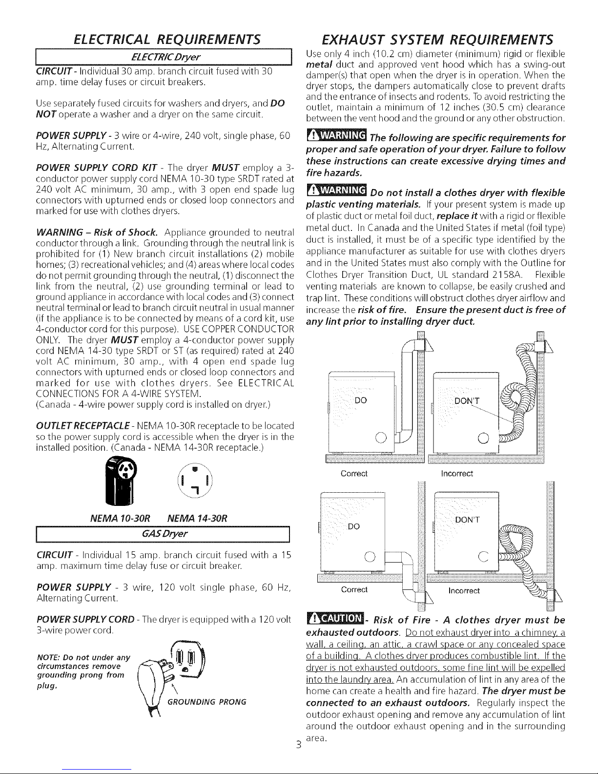
i Use only 4 inch (10.2 cm) diameter (minimum) rigid or flexible
metal duct and approved vent hood which has a swing-out
damper(s) that open when the dryer is in operation. When the
dryer stops, the dampers automatically close to prevent drafts
and the entrance of insects and rodents. Toavoid restricting the
outlet, maintain a minimum of 12 inches (30.5 cm) clearance
between the vent hood and the ground or any other obstruction.
The following are specific requirements for
proper and safe operation of your dryer. Failure to follow
these instructions can create excessive drying times and
fire hazards,
Do not install a clothes dryer with flexible
plastic venting materials, If your present system is made up
of plastic duct or metal foil duct, replace it with a rigid or flexible
metal duct. In Canada and the United States if metal (foil type)
duct is installed, it must be of a specific type identified by the
appliance manufacturer assuitable for use with clothes dryers
and in the United States must also comply with the Outline for
Clothes Dryer Transition Duct, UL standard 2158A. Flexible
venting materials are known to collapse, be easily crushed and
trap lint. Theseconditions will obstruct clothes dryer airflow and
increaseth e risk of fire. Ensure the present duct is free of
any lint prior to instalfing dryer duct,
OUTLET RECEPTACLE- NEMA 10-30R receptacle to be located
sothe power supply cord is accessible when the dryer is in the
installed position. (Canada - NEMA 14-30R receptacle.)
NEMA 10-30R NEMA 14-30R
[ GASDryer j
CIRCUIT- Individual 15 amp. branch circuit fused with a 15
amp. maximum time delay fuse or circuit breaker.
POWER SUPPLY - 3 wire, 120 volt single phase, 60 Hz,
Alternating Current.
POWER SUPPLYCORD- The dryer isequipped with a 120 volt
3-wire power cord.
NOTE: Do not under any _-_{_1_ t
circumstances remove
grounding prong from
plug.
G PRONG
Correct Incorrect
_- Risk of Fire - A clothes dryer must be
exhausted outdoors. Do not exhaust dryer into a chimney, a
wall, a ceiling, an attic, a crawl space or any concealed space
of a buildinq. A clothes dryer produces combustible lint. If the
dryer is not exhausted outdoors, some fine lint will be expelled
into the laundry area. An accumulation of lint in any area of the
home can create a health and fire hazard. The dryer must be
connected to an exhaust outdoors. Regularly inspect the
outdoor exhaust opening and remove any accumulation of lint
around the outdoor exhaust opening and in the surrounding
area.
Page 4
Do not allow combustible materials {for
example: clothing, draperies/curtains, paper) to come in
contact with exhaust system. The dryer MUST NOT be
exhausted into a chimney, a wall, a ceiling, or any concealed
space of a building which can accumulate lint, resulting in a fire
hazard.
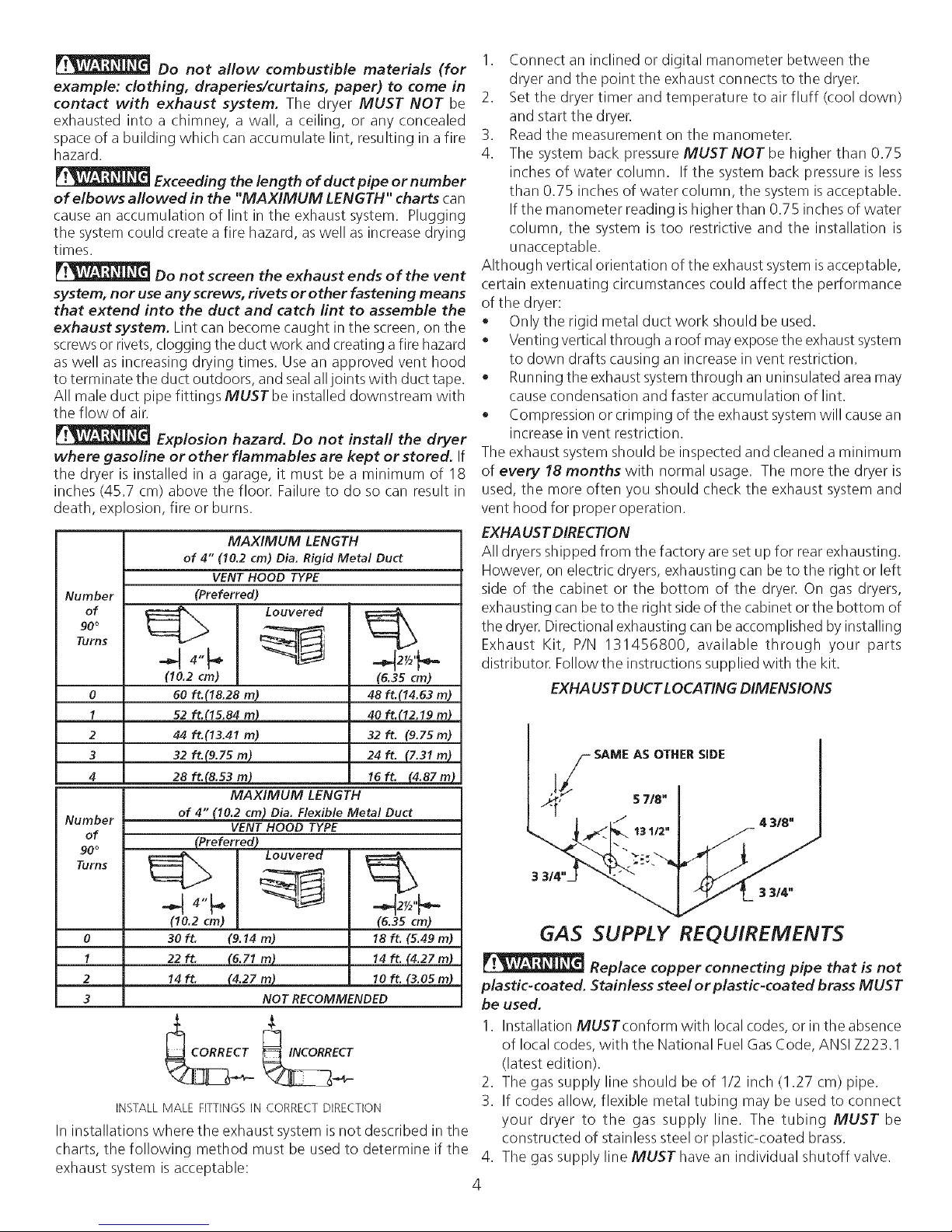
Exceeding the length of duct pipe or number
of elbows allowed in the "MAXIMUM LENGTH" charts can
cause an accumulation of lint in the exhaust system. Plugging
the system could create a fire hazard, aswell as increase drying
times.
Do not screen the exhaust ends of the vent
system, nor use any screws, rivets or other fastening means
that extend into the duct and catch lint to assemble the
exhaust system. Lint can become caught in the screen, on the
screws or rivets,clogging the duct work and creating a fire hazard
as well as increasing drying times. Use an approved vent hood
to terminate the duct outdoors, and sealall joints with duct tape.
All male duct pipe fittings MUST be installed downstream with
the flow of air.
Explosion hazard. Do not install the dryer
where gasoline or other flammables are kept or stored. If
the dryer is installed in a garage, it must be a minimum of 18
inches (45.7 cm) above the floor. Failure to do so can result in
death, explosion, fire or burns.
MAXIMUM LENGTH
of 4" 110.2 cm) Dia. Rigid Metal Duct
VENT HOOD TYPE
Number
of
90 °
Turns
0
1
2
3
4
Number
of
90 °
Turns
(Preferred)
Louvered
(10.2 cm)
60 ft.(18.28 m)
52 ft.(IS.84m)
44 ft.113.41 m)
32 ft.(9.75 m)
28 ft.(8.53 m)
MAXIMUM LENGTH
of 4" (10.2 cm) Dia. Flexible Metal Duct
VENT HOOD TYPE
(Preferred)
24ft. (7.31m)
(6.35 cm)
48 ft.(14.63 m)
40 ft.(12.19 m_
32ft. (9.7Sin)
16 ft. (4.87 m)
1. Connect an inclined or digital manometer between the
dryer and the point the exhaust connects to the dryer.
2. Set the dryer timer and temperature to air fluff (cool down)
and start the dryer.
3. Readthe measurement on the manometer.
4. The system back pressure MUST NOT be higher than 0.75
inches of water column. If the system back pressure is less
than 0.75 inches of water column, the system is acceptable.
Ifthe manometer reading ishigher than 0.75 inches of water
column, the system is too restrictive and the installation is
unacceptable.
Although vertical orientation of the exhaust system isacceptable,
certain extenuating circumstances could affect the performance
of the dryer:
• Only the rigid metal duct work should be used.
• Venting verticalthrough a roof may exposethe exhaustsystem
to down drafts causing an increase in vent restriction.
• Running the exhaust systemthrough an uninsulated area may
cause condensation and faster accumulation of lint.
• Compression or crimping of the exhaust system will cause an
increase in vent restriction.
The exhaust system should be inspected and cleaned a minimum
of every 18 months with normal usage. The more the dryer is
used, the more often you should check the exhaust system and
vent hood for proper operation.
EXHAUST DIRECTION
All dryers shipped from the factory are set up for rear exhausting.
However, on electric dryers, exhausting can be to the right or left
side of the cabinet or the bottom of the dryer. On gas dryers,
exhausting can beto the right side of the cabinet or the bottom of
the dryer. Directional exhausting can be accomplished by installing
Exhaust Kit, P/N 131456800, available through your parts
distributor. Follow the instructions supplied with the kit.
EXHAUST DUCT LOCATING DIMENSIONS
SAME AS OTHER SiDE
I Louvered
0
1
2
3
INSTALL MALE FITTINGS IN CORRECT DIRECTION
3Oft. 19.14m)
22 ft. (6.71 m)
14 ft. (4.27 m)
NOT RECOMMENDED
In installations where the exhaust system is not described in the
charts, the following method must be used to determine if the 4.
exhaust system is acceptable:
(6.35 cm)
18 ft. (5.49 m)
14 ft. (4.27 m)
1oft. (3.05m)
GAS SUPPLY REQUIREMENTS
Replace copper connecting pipe that is not
plastic-coated. Stainless steel or plastic-coated brass MUST
be used.
I. Installation MUSTconform with local codes, or in the absence
of local codes, with the National Fuel Gas Code, ANSI Z223.1
(latest edition).
2. The gas supply line should be of 1/2 inch (1.27 cm) pipe.
3. If codes allow, flexible metal tubing may be used to connect
your dryer to the gas supply line. The tubing MUST be
constructed of stainless steel or plastic-coated brass.
The gas supply line MUST have an individual shutoff valve.
4
Page 5
5. A1/8inch(0.32cm) N.RT.plugged tapping, accessible for test gauge connection, MUST be installed immediately upstream
of the gas supply connection to the dryer.
6. The dryer MUSTbe disconnected from the gas supply piping system during any pressuretesting of the gassupply piping system
at test pressures in excess of 1/2 psig (3.45 kPa).
7. The dryer MUST be isolated from the gas supply piping system during any pressure testing of the gas supply piping system
at test pressures equal to or lessthan
1/2 psig (3.45 kPa).
LOCATION OF YOUR DRYER
DO NOT INSTALL YOUR DRYER:
1. In an area exposed to dripping water or outside weather conditions.
2. In an area where it will come in contact with curtains, drapes, or anything that will obstruct the flow of combustion and
ventilation air.
3. On carpet. Floor MUSTbe solid with a maximum slope of 1 inch (2.54 cm).
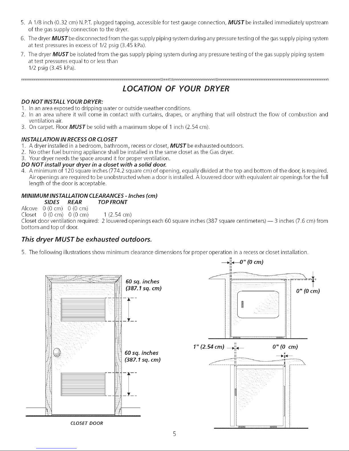
INSTALLATION IN RECESSOR CLOSET
I. A dryer installed in a bedroom, bathroom, recessor closet, MUST be exhausted outdoors.
2. No other fuel burning appliance shall be installed in the same closet as the Gasdryer.
3. Your dryer needs the space around it for proper ventilation.
DO NOT install your dryer in a closet with a solid door.
4. A minimum of 120 square inches (774.2 square cm) of opening, equally divided at the top and bottom of the door, is required.
Air openings are required to be unobstructed when a door is installed. A Iouvered door with equivalent air openings for the full
length of the door isacceptable.
MINIMUM INSTALLATION CLEARANCES - Inches (cm)
SIDES REAR TOPFRONT
Alcove 0(0cm) 0(0cm)
Closet 0 (0 cm) 0 (0 cm) 1 (2.54 cm)
Closet door ventilation required: 2 Iouvered openings each 60 square inches (387 square centimeters) -- 3 inches (7.6 cm) from
bottom and top of door.
This dryer MUST be exhausted outdoors.
5. The following illustrations show minimum clearance dimensions for proper operation in a recessorcloset installation.
H
---_ii_" (0 cm)
H
0" (0 cm)
_,,IJV,*! r,Y_U_
1" (2.54 cm) _11 _
"" O" (0 cm)
II ii
II _11_
CLOSET DOOR
Page 6
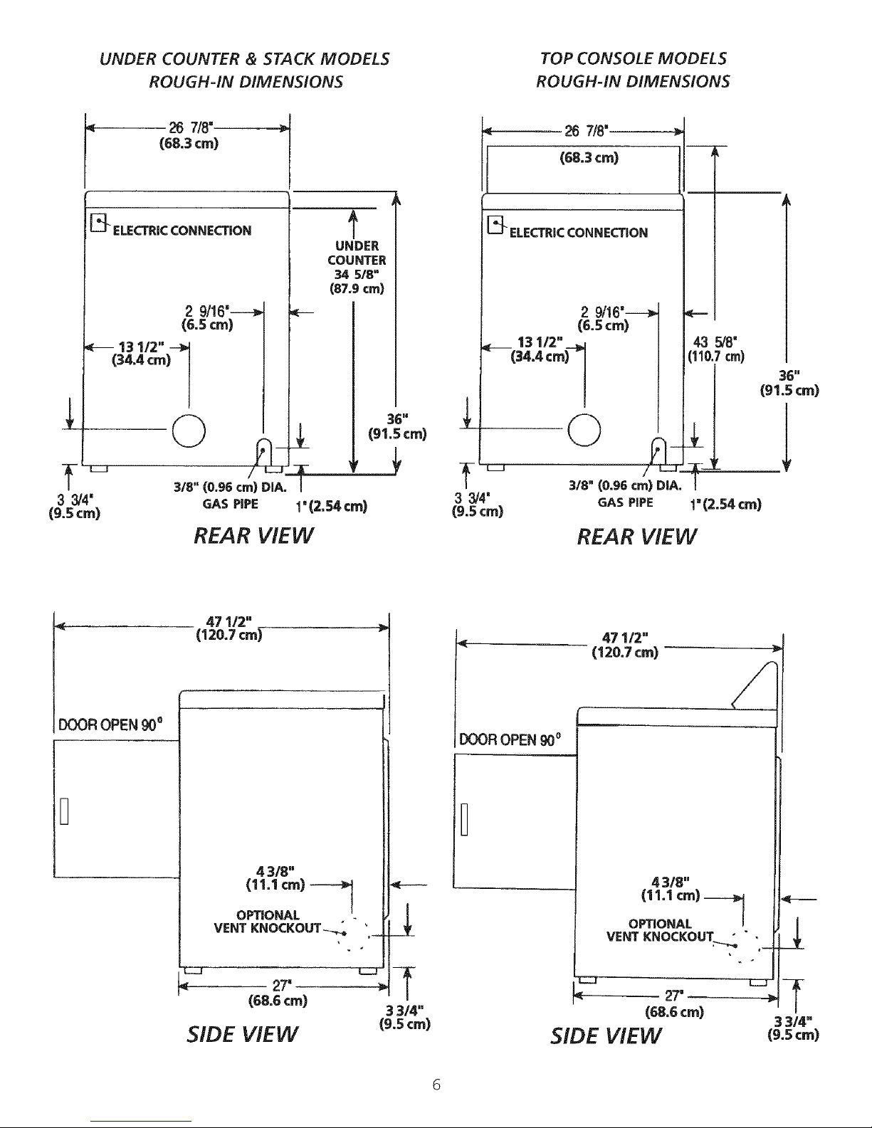
UNDER COUNTER & STACK MODELS
ROUGH-IN DIMENSIONS
(68.3cm)
I 26 7/8"
TOP CONSOLE MODELS
ROUGH-IN DIMENSIONS
26 7/8"
(68.3cm)
[_ ELECTRICCONNECTION
13 1/2"
(34.4 cm) ]
33/4'
(9.5 crn)
2 9/16'---_
(6.5 ¢m)
3/8" (0.96 cm) DIA.
GAS PIPE
REAR VIEW
471/2"
(120.7 cm)
UNDER
COUNTER
34 518"
(87.9 cm)
t
I
1'12._¢m1
36"
(91.S cm)
33/4'
(9.5 cm)
I
ELECTRICCONNECTION
3/8" (0.96 era) DIA.
GAS PiPE
REAR VIEW
43 _8'
cm)
36 n
(91.S cm)
I" (2.54 cm)
DOOR OPEN 90o
B
4 3/8"
(11.1 cm) -_
OPTIONAL
VENT KNOCKOUT-_
E23
27"
(68.6 ¢m)
SIDE ViEW
4--
3 314"
(9.5 cm)
DOOR OPEN 900
Z3
< 27"
(68.6 cm)
SIDE VIEW
6
Page 7

MOBILE HOME INSTALLATION
1. Dryer MUST be exhausted outside (outdoors, not beneath
the mobile home) using metal ducting that will not support
combustion. Metal ducting must be 4 inches (10.16 cm) in
diameter with no obstructions. Rigid metal duct is preferred.
2. If dryer is exhausted through the floor and area beneath
the mobile home is enclosed, the exhaust system MUST
terminate outside the enclosure with the termination
securely fastened to the mobile home structure.
3. When installing a gas dryer into a mobile home, a provision
must be made for outside make up air.This provision isto
be not lessthan twice the area of the dryer exhaust outlet.
4. This dryer MUST be fastened to the floor. Mobile Home
Installation Kit No. 169840 is available from your dealer.
5. Refer to pages 2 and 3 for other important venting
requirements.
6. Installation MUSTconform to current Manufactured Home
Construction & Safety Standard (which is a Federal
Regulation Title 24 CFR-Part32-80) or when such standard
is not applicable, with American National Standard for
Mobile Homes. In Canada, the CSA Z240 is applicable.
The dr/er isdesigned under ANSI Z21.5.1 for
HOME USE only.
UNPACKING
I. Using the four shipping carton corner posts (two on each
side), carefully laythe dryer on its left side and remove foam
shipping base.
_:_ Topreventdamage, do not usethe control panel
as a means to pick up or move the dryer.
NOTE: On under counter model clothes dryers, the top panel
may be removed for installation.
Return the dryer to an upright position.
__,_ ING
Correct
Correct
OK
©
Incorrect
¸i¸!¸¸
DON'T
Incorrect
O
_Wfrb.
L
REVERSING DOOR SWING
Your dryer is designed so the door swing may be reversed at
any time without additional parts. Conversion isaccomplished
by transferring hinges to the opposite side of the cabinet.
To change the direction of the door opening:
I. Open the dryer door. Remove the four hinge hole plugsfrom
the left side of the door opening. Place nearby for future
installation. NOTE: You may need a plastic knife to help pull
out the plugs. Becareful not to scratch the paint.
2. Remove the four screws that secure the door hinges to the
dryer front panel (see below). NOTE: Remove one screw
from each of the two hinges first. Holdthe door firmly before
removing the last two screws.
3. Rotate the door 180° and reinstall the door hinges to the
dryer front panel with the four screws.
4. Install the four hinge hole plugs in the open screw holes on
the right sideof the door opening.
Incorrect
REMOVE 4 SCREWS
(ONE FROM EACH
HINGE FIRST)
Page 8

ELECTRICAL INSTALLATION
i
proper and safe electrical installation of your dryer. Failure
to follow these instructions can create electrical shock and/
or a fire hazard.
[] This appliance MUST be properly arounded. Electricalshock
can result if the dryer is not properly grounded. Follow the
instructions in this manual for proper grounding.
[] Do not usean extension cord with this dryer. Someextension
cords are not designed to withstand the amounts of electrical
current this dryer utilizes and can melt, creating electrical shock
and/or fire hazard. Locatethe dryer within reachof the receptacle
for the length power cord to be purchased, allowing some slack
in the cord. Refer to the pre-installation requirements in this
manual for the proper power cord to be purchased.
[] A U.L. approved strain relief must be installed onto power
cord. If the strain relief is not attached, the cord can be pulled
out of the dryer and can be cut by any movement of the cord,
resulting in electrical shock.
[] Do not use an aluminum wired receptacle with a copper
wired power cord and pluq (or vice versa). A chemical reaction
occurs between copper and aluminum and can cause electrical
shorts. The proper wiring and receptacle is a copper wired
power cord with a copper wired receptacle.
ALL ELECTRICDryers
The following are specific requirements for
]
I Canadian ELECTRICDryer I
Improper connection of the equipment grounding
conductor can result in a risk of electrical shock. Check with a
licensedelectrician if you are in doubt asto whether the appliance
isproperly grounded.
Foraarounded, cord-connected dryer:
1. Thedryer must be grounded. In the event of a malfunction or
breakdown, grounding will reduce the risk of electrical shock
by a path of least resistance for electrical current.
.
Sinceyour dryer isequipped with a power supply cord having
an equipment-grounding conductor and agrounding plug, the
plug must be plugged into an appropriate outlet that isproperly
installed and grounded in accordance with all local codes and
ordinances. If in doubt, call a licensed electrician.Do not
modify plug provided with the appliance.
I
I. The dryer isequipped with athree-prong (grounding) plug for
your protection against shock hazard and should be plugged
directly into a properly grounded three-prong receptacle. Do
not cut or remove the grounding prong from the plug.
ALL GAS Dryers
J
NOTE: Dryers operating on 208 volt power supply will have
longer drying times than operating on 240 volt power supply.
GROUNDING REQUIREMENTS
I
grounding conductor can result in a risk of electrical shock. Check
with a licensed electrician if you are in doubt as to whether the
appliance isproperly grounded.
Foragrounded cord-connected dryer:
1. The dryer MUSTbe grounded. Inthe event of a malfunction
or breakdown, grounding will reduce the riskof electrical shock
by a path of least resistance for electrical current.
2. If your dryer is equipped with a power supply cord having an
equipment-grounding conductor and a grounding plug, the
plug MUST be plugged into an appropriate, copper wired
receptacle that is properly installed and grounded in
accordance with all local codes and ordinances. If in doubt,
call a licensed electrician. Do not modify plug provided
with the appliance.
Fora permanently connected dryer:
1. ThedryerMUSTbe connected to agrounded metal, permanent
wiring system; or an equipment grounding conductor must be
run with the circuit conductors and connected to the
equipment-grounding terminal or lead on the appliance.
Non-Canadian ELECTR/CDryer
Improper connection of the equipment
I
8
Page 9

ELECTRICAL CONNECTIONS
FOR 3-WIRE SYSTEM
ELECTRICAL CONNECTIONS
FOR 4-WIRE SYSTEM
i Non-Canadian ELECTR/CDryer i
1. Remove the screws securing the terminal block accesscover
and the strain relief mounting bracket located on the
back of the dryer upper corner.
2. Install a U.L approved strain relief into the power cord entry
hole of the mounting bracket. Finger tighten the nut only at
this time.
GREEN GROUND SCREW
NEUTRAL
GROUND
WIRE
SILVER TERMINAL
IUT
TIGHTEN NUT TO
THESE THREADS
Non-Canadian ELECTR/CDryer j
1. Remove the screws securing the terminal block accesscover
and the strain relief mounting bracket located on the back of
the dryer upper corner.
2. Install a U.L approved strain relief in the entry hole of the
mounting bracket. Fingertighten the nut only at this time.
GREEN GREEN POWERCORD
GROUND_ROUND WIRE SILVER TERMINAL
SCREW _ ,TERMINALBLoCK
NEUTRAL __3qlll_
GRO UN DJJ,_----_
WIRE
TIGHTEN NUT
NUT _HREADS
/
REd _ ///_)
/
1POWER 1/._
CORD
3. Removethe ground wire from the green ground screwlocated
above the terminal block.
RELIEF
MOUNTING
BRACKET
POWER CORD
3. Thread a U.L approved 30 amp. power cord, NEMA 10-30
Type SRDT,through the strain relief.
4. Attach the power cord neutral (center wire) conductor to
the silver colored center terminal on the terminal block.
Tighten the screw securely.
5. Attach the remaining two power cord outer conductors to
the outer brass colored terminals on the terminal block.
Tighten both screws securely.
Do not make a sharp bend or crimp wiring/
conductor at connections.
6. Reattach the strain relief mounting bracket to the back of
the dryer with two screws. Tighten screws securely.
7. Tighten the screws securing the cord restraint firmly against
the power cord.
8. Tighten the strain relief nut securely so that the strain relief
does not turn.
9. Reinstall the terminal block cover.
_ TYPICAL 4
CONDUCTOR BLACK
WHITE
TYPICAL 4 _-'_,_
CONDUCTOR "GREEN
30 AMP NEMA 14-30 TYPE SRDT OR
RED 240V
4. Thread a U.L approved 30 amp power cord, NEMA 14-30
type STor SRDTthrough the strain relief.
5. Attach the green power cord ground wire to the cabinet with
the green ground screw.
Attach the white (neutral) power cord conductor from the
power cord and the neutral ground wire from the dryer harness
to the silver-colored center terminal on the terminal block.
Tighten the screw securely.
7. Attach the red and black power cord conductors to the outer
brass-colored terminals on the terminal block.
Do not make a sharp bend or crimp wiring/
conductor at the connections.
8. Tighten the screws securing the cord restraint firmly against
the power cord.
9. Tighten the strain relief nut securely so the strain relief does
not turn.
10. Reinstall the terminal block accesscover.
9
Page 10

INSTALLATION
I. GAS CONNECTION (Gas dryers only)
a. Remove the shipping cap from gas pipe at the rear of
the dryer.
NOTE: DO NOTconnect the dryer to L.Rgas service without
converting the gas valve. An L.R conversion kit must
be installed by a qualified gas technician.
Connect a 1/2 inch (1.27 cm) I.D. semi-rigid or approved
pipe from gas supply line to the 3/8 inch (0.96 cm) pipe
located on the back of the dryer. Use a I/2 inch to 3/8
inch (1.27 cm to 0.96 cm) reducer for a connection.
Apply an approved thread sealer that is resistant to the
corrosive action of liquefied gaseson all pipe connections.
c. Open the shutoff valve in the gas supply line.
d. Testall connections bybrushing on asoapy water solution.
NEVER TESTFOR GAS LEAKS WITH AN OPENFLAME.
2. Connect the exhaust duct to outside exhaust system. Use
duct tape to seal all joints.
3. With the dryer in its final position, adjust one or more of the
legs until the dryer is resting solid on all four legs. Place a
level on top of the dryer. THE DRYER MUST BE LEVEL
AND RESTING SOLID ON ALL FOUR LEGS.
4. Plug the power cord into a grounded outlet.
If your dryer does not operate, please review the "Avoid
Service Checklist" located in your Owner's Guide before
calling for service.
Placethese instructions in a location near the dryer for futu re
reference.
Tostack your dryer on a compatible washer call your local
dealer to find your local distributor to purchase a stacking
kit accessorypart number 5303937141.
NOTE:
A wiring diagram islocated inside the dryer console or
behind the right side panel.
REPLA CEMENT PARTS
If replacement parts are needed for your dryer, contact the
source where you purchased your dryer.
Label all wires prior to disconnection when
servicing controls. Wiring errors can cause improper and
dangerous operation. Verify proper operation after servicing.
Destroy the carton and plastic bags after the
dryer is unpacked. Children might use them for play. Cartons
covered with rugs, bedspreads, or plastic sheets can become
airtight chambers causing suffocation. Place all materials in a
garbage container or make materials inaccessible to children.
NOTE: Check to ensure the power is off at circuit breaker/
fuse boxbefore plugging the power cord into the outlet.
5. Turn on the power atthe circuit breaker/fuse box.
Before operating the dryer, make sure the
dryer area is clear and free from combustible materials,
gasoline, and other flammable vapors. Also see that
nothing (such as boxes, clothing, etc.) obstructs the flow
of combustion and ventilation air
6. Run the dryer through a cycle check for proper
operation.
NOTE: On gas dryers, before the burner will light, it is
necessary for the gas line to be bled of air. If the burner
does not light within 45 seconds the first time the dryer is
turned on, the safety switch will shut the burner off. If this
happens, turn the timer to "OFF" and wait 5 minutes before
making another attempt to light.
The instructions in this manual and all other
literature included with this dryer are not meant to cover every
possible condition and situation that may occur. Good safe
practice and caution MUSTbe applied when installing, operating
and maintaining any appliance.
10
Page 11

Tabla de Materias
Requerimientos de instalaciOn preliminares ........................................................................................................................... 12
Requerimientos elOctricos ................................................................................................................................................... 12
Requerimientos del sistema de escape.............................................................................................................................. 12-13
Requerimientos del suministro de gas.................................................................................................................................... 13
UbicaciOn de su secadora ..................................................................................................................................................... 14
Dimensiones para la instalaciOn........................................................................................................................................... 15
InstalaciOn en casas mOviles................................................................................................................................................. 16
Desembalaje .................................................................................................................................................................... 16
Puerta reversible ................................................................................................................................................................ 16
InstalaciOn elOctrica ........................................................................................................................................................... 17
Requerimientos para la puesta a tierra .................................................................................................................................. 17
(onexiOnes elOctricas - trifilares .......................................................................................................................................... 18
ConexiOnes elOctricas - tetrafilares ....................................................................................................................................... 18
InstalaciOn ....................................................................................................................................................................... 19
Piezas de recambio ............................................................................................................................................................ 19
t
SEGURIDAD de SECADORA
La instalacion y el servicio de la Secadora de ropa se deben realizar pot un instalador calificado, la agencia de servicio o el
surtidor de gas.
Instale la Secadora de ropa segun las instrucciones del fabricante y los cOdigos locales. Antes de comenzar la instalaciOn,
lea cuidadosamente estas instrucciones. Esto simplificara la instalaciOn y asegurara que la secadora se instale correctamente
y de manera segura. Despues de completar la instalacion, coloque estas instrucciones cerca de la secadora para referencia
futura.
NO TA:La alimentacion el_ctrica para la secadora debera cumplir con los codigos y reglamen tos locales y con la ultima ediciOn
del C_digo El_ctrico National, ANSI/NFPA 70 o en Canada CSA C22.1 Codigo Electrico Canadiense, Parte 1.
NO TA: La alimentaciOn de gas para la secadora debera cumplir con los codigos y reglamentos locales y con la ultima edicion
del C_digo Nacional para Gases Combustibles, ANSI Z223.1 o en Canada CAN/CGA B149.12.
NO TA:La secadora esta clasificada para USODOMESTICO solamente, de acuerdo con la norma ANSI Z21.5.1 o ANSI/UL 2158 -
CAN/CSA C22.2 No. 112 (las ultimas edici_nes). Esta secadora no se recomienda para uso commercial tal como en restaurantes,
salones de belleza, etc.
Su seguridad y la seguddad de terceros son muy importantes.
Hemos proporcionado muchos mensajes irnportantes para la seguridad en las Instrucciones de OperaciOn del Manual de Uso y
Mantenimiento, las Instrucciones de InstalaciOn yen el mismo aparato. Siempre lea y obedezca todos los mensajes para seguridad.
_Este simbolo significa alerta. Estesimbolo Io alerta acerca de peligros que pueden matar o lesionar, tanto a usted como a otras
personas. Todos los mensajes de seguridad seran precedidos por el simbolo de alerta para su seguridad y la palabra "PEI.IGRO o
ADVERTENCIA " (DANGER" o WARNING). Estaspalabrassignifican:
PELIGRO (DANGER) Usted morira o resultara seriamente lesionado si no sigue las instrucciones siguientes.
ADVERTENCIA (WARNING) Usted puede modr o resultar sedamente lesionado si no sigue las instrucciones
siguientes.
Todos los mensajes de seguridad identificaran el peligro, le diran a usted como reducir la posibilidad de lesion y tambien
• _uede suceder si no se siguen las instrucciones.
RIESGODEINCENDIO. Parasu seguridad, siga las instrucciones contenidas en este manual a fin de reducir a un
m_nim_losriesg_sdein_endi_explosion_paraevitarda_smateria_es_esi_nespers_na_es_a muerte. GUARDEESTAS
INSTRUCCIONES.
Noalmacene ni utilice gasolina u otrosvapores y liquidos inflamables en la proximidad de _ste o de cualquier otro artefacto el_ctrico.
QUEDEBEHACER SIPERCIBEOLORA GAS
. No trate de encender ning_n artefacto el_ctrico.
. No toque ningOn interruptor el_ctrico; no useningOn tel_fono en suedificio.
. Haga salir a todos los ocupantes de la habitation, del edificio ydel lugar.
. Llame a su proveedor de gas desde el tel_fono de un vecino. Siga las instrucciones del proveedor de gas.
. Sino Iogra comunicarse con su proveedor de gas, Ilame al departamento de bomberos.
LainstalaciOny el servicio de mantenimiento debe de realizarlos un instalador calificado, la agencia de servicios o el proveedor de gas.
REQ UERIMIEN TOS D E INS TALA C_ON PREL IMINA RES
Herramientas y materiales necesarios para la instalacion:
1. Destornillador Phillips
2. Alicates universales
3. Nivel de carpintero
4. Destornillador para tornillo de cabeza plana o recta
5. Cinta para ductos
6. Ducto metalico rigido o flexible de 4" (10,2 cm)
7. Caperuza de salida
8. Sellador de tuberias (gas)
9. Un cuchillo de plastico
11
Page 12

REQUERIMIENTOS ELECTRICOS
[
Secadoras ELECFR/CAS
CIRCUITO- Circuito derivado individual de 30 amperes,con fusibles
de 30 amp. del tipo de retardo o disyuntores.
Useunos circuitos con un interruptor ofusible separadamente para
laslavadoras ylassecadoras y no hacefuncionar una lavadora y una
secadora sobre el mismo circuito.
ALIMENTACIONELECTRICA - Corriente alterna, monofasica, 60
Hz, 240 voltios; trifilar. (Canada - 240 voltios, monofasico, 60 Hz,
corrienta alterna.)
CORDON ELECTRICO - En la secadora se DEBE usar un cordon
eBctrico trifilar NEMA 10-30 tipo SRDT para un voltaje nominal
minimo de 240 voltios CA, 30 amp, con 3 conectores de horquillas
conterminales abiertosyextremos dirigidos haciaarriba oconectores
de anillo cerrado y marcados para uso en secadoras de ropa.
AVERTISSEMENT-Risquedechoc_lectrique. Unappareil misa
laterre a I'aide d'un lien ou c_bleconducteur neutre. Laraise a la
terre a I'aide d'un conducteur ou c_ble neutre est interdite dans les
cas suivants : (1) les installations de nouveau circuit devir6 (2) les
maisons mobiles (3) lesv_hicules rOcr_atifs ou caravanes et (4) les
rOgionso_ lescodes Iocauxinterdisent la misea laterre a I'aide d'u n
c_bleou conducteu rneutre. (1)D_branchez leconducteur ou c_ble
du neutre, (2) utilisez la borne de mise a la terre ou lec_ble de mise
a la terre de I'appareil conform_ment aux codes Iocaux et (3)
connectez ou branchez la borne neutre ou le c_ble au neutre du
circuit dOvir6de lamani_re habituelle(si I'appareil doit Ctreconnecte
a I'aide d'un cordon, utilisezuncordon a4 c_blesou ills pour cefaire).
N'UTILISEZQUE DESCABLESOU FILSENCUIVRE. SeDEBEutilizar
un cordon eBctrico tetrafilar NEMA 14-30tipoSRDToST(como sea
necesario) para un voltaje nominal minimo de 240 voltios CA, 30
amp con4conectoresde horquillasconterminales abiertosyextremos
dirigidos Inaciaarribao conectores deanillo cerrado y marcados para
uso en secadoras de ropa. Ver CONEXIONESELECTRICASPARA
SISTEMASTETRAFILARES.
(Canada - un cord6n de suministro de energia de 4 alambres es
instalado en la secadora.)
TOMACORRIENTE- Eltomacorriente NEMA 10-30R debe estar
ubicado de manera que el cordon eBctrico Ilegue hasta 61cuando
lasecadora est6 instalada. (Canada - receptaculo NEMA 14-30R.)
ALIMENTACION I I I CAJAPRINCIPALDEFUSIBLESCONCONDUCTORNEUTRO
FUSIBLESDEACCION RETARDADA
DE30 AMP O DISYUNTOR
CONDUCTOR NEUTRO
ELEC_ ClCLosPUESTOATIERRA,TRIFILAR,120-240VOLTIOS60.
TOMACORRIENTE
(COBRE)
INSTALACION SUJETA A LOS
REGLAMENTOSLOCALES NEMA 10-30R (COBRE)
I Secadorasa GAS ]
CIRCUITO- Circuito individual derivado de I 5 amp, con fusibles de
15 amp. de retardo maximo o disyuntor.
ALIMENTACIONELECTRICA- Corriente alterna, monofasica,60 Hz,
120 voltios, trifilar.
CORDONELECTRICO - La secadora esta equipada con un cordon
eBctrico trifilar para 120 voltios.
NOTA: No saque por C_ _
ningOn motivo la
espiga de puesta a PICA DE PUESTA
tierra del enchufe. TIERRA
REQUERIMIENTOS DEL SISTEMA DE ESCAPE
Utilicesolamenteductosmetalicos rigidosoflexibles de 4"
J
(10,2 cm) de diametro (minim@ y una caperuza de salida de uso
aprobado, con registrosque giren haciaafuera que seabren cuando
la secadora se encuentra en funcionamiento. Cuando la secadora
sedetiene, losregistros secierran automaticamente para evitar las
corrientes de aire y la entrada de insectos y roedores. Para evitar
obstruir lasalida, mantenga una altura libre minima de 12"(30,5 cm)
entrela )eruza desalidayelpiso o entre cualquier otra obstrucciOn.
Los siguientes requerimientos son
especificos para el funcionamiento correcto y seguro de su
secadora. El incumplimiento de estas instrucciones puede
causar prolongacion excesiva del tiempo de secado y riesgos
de incendio.
No instale la Secadora con materiales de ventilaciOn pBsticos
flexibles. EnCanada ylos EstadosUnidos siel conducto esde metal
(tipo hoja dealuminio), estedebe serdeun tipo especifico identificado
por el fabricante, recomendado para el uso con Secadoras;yen los
Estados Unidos debe ademas cumplir con la norma UL2158A. Los
materiales de ventilaciOn flexibles sepueden colapsar o apachurrar
facilmenteyatrapar pelusa.Estascondiciones obstruiran lacirculaciOn
de airede laSecadoraderopa yaumentaran elriesgo deincendio.
Sisusistema de escapeactual tiene ductos de pBstico o de laminas
metalicas delgadas, reempBcelo con un ducto metalico rigido o
flexible. Aseg(lrese de que los ductos existentes no tengan
pelusas antes de instalar el ducto de la secadora.
8888 88888
CORRECTO INCORRECTO
_Risque d'incendie - una Secadora de ropa se debe ventilar
alaire libre, No ventile la Secadora en una chimenea, una pared,
un techo, un atico, un espacio cerrado o ningun espacio encubierto
del edificio. UnesOcheusealinge produit de lacharpie combustible.
Siel escape de la secadora no sedirige al exterior, algunas pelusas
finas seran sopladas haciael recinto donde seefectLia el lavado. La
acumulaciOn de pel_sas en cualquier lugar de la casa, puede crear
un peligro para la saludy un riesgo de incendio. La secheuse doit
@treconnectee _ une bouche d'e vacuation vers I'ext_rieu r du
b_timentoudel'immeuble. Vousdevez inspecter r_guli_rement
I'@ent extOrieuret enlever toute accumulation de charpie autour de
1'Oventet dans la cavit6 du conduit d'Ovacuation.
Nopermita que losmaterialescombustibles @orejemplo: laropa,
cortinas/cortinajes, papel)tengan contacto con losductos.
_r Excederla Ionaitud del conducto rigidp o los nOmerosde codos
pe mitidosen Iosdiagramas "LARGOMAXIMO" puededisminuir
lacapacidad deexhaustaciOndelsistema. Obstruir elconducto puede
provocarpeligro deincendio, asicomo aumentar eltiempo de secado.
_No obstruya los extremos del tubo de ventilacion, ni utilice
tornillos remachesu otros medios defijaciOn que puedan obstruir el
conducto yatrapar pelusa. Laspelusaspodrian quedar atrapadas en
losfiltros, en lostornillos o en losremaches,Iocualobstruiria elsistema
de escape ycrearia un riesgodeincendio, asicomotambiOn
prolongaria el tiempo de secado. Use una caperuza de salida
adecuadaparael extremo delducto que salgaalexterior de lavivienda
y selle todas lasjuntas con cinta adhesiva para ductos. Todos los
accesoriosdetuberia machos, DEBENser instalados aguas abajo del
flujo de aire.
12
Page 13

Riesgo de explosi6n. No instale la secadora
donde se guarda gasolina u otros materiales inflamables. Si la
secadora se instala en un garage, ella debe estar pot Io menos 18
pulgadas (45,7 cm) por encima del suelo. Elincumplimiento puede
resultar en la muerte, explosion, incendio, o quemaduras.
m
LARGO MAXIMO
del Conducto Metalico Rigido
de 4" (10,2 cm) de Diametro
TIPO DE CAPERUZA DE SALIDA
(Preferido)
* Sedebe utilizar solamente conductos metalicos rigidos.
Una salida del sistema vertical en el techo, puede exponerle
a un corriente de aire descendente ydisminuir asi su capacidad
de exhaustaciOn.
Elaislante que debe atravesar el sistema puede causar
condensaciOn ydisminuir asi la capacidad de exhaustaciOn
del sistema.
. Lacapacidad de exhaustaciOn de un sistema de exhaustaciOn
comprimido o ondulado puede disminuirse.
El sistema de exhaustaciOn debe de set inspeccionado y limpiado
por Io menos cada 18mesesde uso normal. Cuanto mas la secadora
esta utilizada, masdebe verificar el buen funcionamiento delsistema
de exhaustaciOn y de la tapa del orificio de ventilaciOn.
ogoo -..t4..p. +...
(10_2 cm_ (6.3S cm)
0 60 pies (18,28 m) 48 pies(14,63 m)
1 52 pies (15,84 m) 40 pies(12,19 m)
2 44 pies (13,41 rn) 32 pies (9,75 m)
3 32 pies (9,75 m) 24 pies (7,31 m)
4 28 pies (8,53 m) 16 pies (4,87 m)
LARGO MAXIMO
del Conducto Metalico Flexible
de 4" (10,2 cm) de Diametro
TIPO DE CAPERUZA DE SALIDA
(Preferido)
(10,2 cm) (6.35 cm)
0 30 pies (9,14m) 18pies 3,49m)
1 22 pies (6,71 m) 14 pies ¢,27 rn)
2 14pies (4,27m) 10pies _,05m)
3 NO RECOMENDADO
INSTALE LOS ACCESORIOS MACHOS EN LA DIRECCION CORRECTA
ParalasinstalaciOnescuyassistemade exhaustaciOnnoseencuentre
en el diagrama, se puede utilizar el metodo a continuaciOn para
determinar si el sistema de exhaustaciOn esapropiado.
I. Conecte un manOmetro a tubo inclinado o digital entre la
secadora y el union de exhaustaciOn de la secadora.
2. Ponga el contador de tiempo de la secadora y la temperatura
a aire frio (enfiriamiento), y la secadora en la posiciOn de
marcha.
3. Lea la medida indicada en el manOmetro.
4. La baja presiOn NO DEBEexceder 0.75 pulgada de lacolumna
deagua. SilabajapresiOnesinferiora0.75" delacolumna
deagua, elsistema es aceptable. Sila lectura indica una
presiOn superior a 0.75" de la columna de agua, la capacidad
del circuito es insuficiente y la instalaciOnes inaceptable.
Aungue un sistema vertical seaaceptable, algunas circunstancias
atenuantes pueden afectar el funcionamiento de la secadora:
UBICA CION DEL ESCAPE
Todaslassecadorasvienen de fabrica equipadas con escapetrasero.
Sin embargo, en lassecadoras el_ctricas, el escape puede hacerse
al lado derecho o izquierdo del gabinete o en la parte inferior de la
secadora. Enlas secadoras a gas, el escapedel aire puede estar en
el lado derecho del gabinete o en la parte inferior de la secadora. El
escapedireccional puede efectuarse instalando unJuegode Escape,
P/N 131456800, disponible atrav_s de sudistribuidor de repuestos.
Siga lasinstrucciones que sesuministran con eljuego.
DIMENSIONES PARALA UBICACION DEL DUCTO DE ESCAPE
S IGUAL QIJE IELo'rRo I_DO
"_.. _ - (9,scrn)
REQUERIMIENTOS DEL SUMINISTRO DE GAS
_)__ Reemplace la tuberia de conexi6n de
cobre que no esta recubrida con plastico. El lat6n inoxidable
o recubrido con plastico DEBE SER utilizado.
I. La instalaciOn DEBE hacerse cu mplir con los cOdigos locales o en
ausencia de los mismos, de acuerdo con los estandares del National
Fuel Gas Code (COdigo Nacional para Gases Combustibles), ANSI
Z223.1 (la 01tima edition). Para Canada, el Estandar CAN/CGA
B149 que est6 en vigor.
2. La tuberia de alimentaciOn de gas debe ser de I/2 pulgada
(1,27 cm) de diametro.
3. Siesta permitido por los cOdigos locales, se puede usar tuberia de
metal para conectar su secadora a la linea de suministro de gas.
La tuberia DEBE ser fabricada de acero inoxidable o cobre
recu bierto de plastico.
4. Latu beria de alimentaciOn de gas DEBEtener una Ilave de cierre
individual.
5. Una toma de 1/8 de pulgada (0,32 cm) N.P.T. accesible para
conexiOn del manOmetro de prueba, DEBE ser instalada
inmediatamente aguas arriba de la conexiOn de la tuberia de
alimentaciOn de gas a la secadora.
6. La secadora DEBE ser desconectada del sistema de tuberias de
alimentaciOn de gas durante cualquier ensayo de presiOn del
sistema de tu berias de alimentaciOn de gas realizado a presiones
de prueba de mas de I/2 Ibs/pulg. 2 (3,45 kPa).
7. Lasecadora DEBEaislarse del sistema de tu berias de alimentaciOn
de gas durante cualquier ensayo de presiOn del sistema detuberias
de alimentaciOn de gas realizado en ensayos de presiOn iguales o
inferiores a 1/2 Ibs/pulg. 2 (3,45 kPa).
13
Page 14

UBICA CION DE SU SECADORA
NO INSTALESUSECADORA:
I. En un lugar donde puede haber goteos de agua o quede
expuesta a lasindemencias del tiempo.
2. En un area donde pueda entrar en contacto con cortinas,
cortinajes o cualquier otra cosa que obstruya el flujo de
combusti6n yventilaci6n de aire.
3. Sobre alfombras. El piso DEBE ser firme con un desnivel
maximo de 1 pulgada (2,54 cm).
INSTALACION DENTRO DE UN NICHO OARMARIO
I. Sila secadora esinstalada en un dormitorio, cuartode baflo,
nicho o armario, el tubo del escapeDEBE serinstalado hacia
el exterior.
2. No se debe instalar ningOn otro artefacto que queme
combustible en el mismo armario en que esta instalada la
secadora a Gas.
3. La secadora necesita espacio a su alrededor para una
ventilaciOn adecuada.
NO INSTALELA SECADORA EN UNARMARIO CON PUERTA
MACIZA.
4. Serequiere como minimo una abertura de 120 pulgadas cua-
dradas (774,2 cm2),dividida equitativamente para la parte
superior e inferior de la puerta. Cuando seinstala una puerta,
es necesario proveer aberturas para el aire. Una puerta
apersianada con aberturas para el aire en todo el largo de la
puerta es aceptable.
DESPEJESMiNIMOS DEINSTALACION (Pulgadas)
PARTE PARTE PARTE
DELANTERA LADOS TRASERA SUPERIOR
Alcoba o
encastradas0(0cm) 0(0cm) 0(0cm) 15(38,1cm)
Armario I(2,54cm) 0(0cm) 0(0cm) 15(38,1cm)
VentilaciOn requirida en la puerta del armario: dos aberturas
rejilladas cada 60 pulg.2 (387 cm2)-- 3" (7,6 cm) desde la
parte inferior y superior de la puetra.
EL TUBO DEL ESCAPE DE LA SECADORA DEBE SER
INSTALADO HACIA EL EXTERIOR.
5. LassiguientesilustraciOnesmuestran lasdimensiOnesminimas
de espacio libre que debe existir para elbuen funcionamiento
de lasecadora cuando seinstala en un rlicbo o en un armario.
\
PUERTA DEL ARMARIO
NOTA:
Secadoras encastradas o superpuestas -- 0 pulgada (0 cm),para los lados, parte trasera yen la parte superior.
i
(38,1era)
,, --_i_--1" (2,54cm)
II u
_11 _ 0 (0 Cm) . . .
,, II _,_ O {0cm)
II II II
O"(0cm)
O"(0 cm)
Si se desea una instalaci6n debajo de un mostrador , ESIMPRESCINDIBLE instalar un conjunto de hoja superior en la
lavadora, numero de parte 131629100. Este conjunto es disponible de un distribuidor de partes autorizado.
INSTALACION DEBAJO DE UN MOSTRADOR
* Se requiere un mostrador hecho a medida.
14
Page 15

MODELOS DE DEBAJO
DE MOSTRADOR Y APILADORES
DIMENSIONES PARA LA INSTALACION
MODEL OS A UTONOMOS
CON CONSOLA SUPERIOR
DIMENSIONES PARA LA #NSTALAC!ON
26 7/8"
(68,3 cm)
[_ CONEXION ELE:CTRICA
2 9/16" (6,5 cm) --_
-_- L_J
3 3/4"
(9,Scm)
BAJO DEL
MOSTRADOR
(87,9 cm)
©
CONEXION DE LA
TUBERiA DE GAS
DE 3/8" (0,96 cm)
VISTA POSTERIOR
47 1/2"
(120,7 cm)
1" (2,54 cm)
34 5/8"
36"
(91,5cm)
[_ CONEXION ELECTRICA
29/16" (6,5cm)
13 1/2" -_
(34,4 cm) I
3 3/4" (9,5 cm)
VISTA POSTERIOR
©
CONEXION DE LA
TUBERiA DE GAS
DE 3/8" (0,96cm)
47 1/2"
(120,7 cm)
9F--t
43 5/8"
(110,7cm)
36"
(91,Scm)
1" (2,54 cm)
PUERTA
ABIERTA A 90 °
B
43/8" (11,1 cm)
DISCOOPCIONAL
REMOVIBLE _
PARA
VENTILA CION
EE3
27"
(68, 6 cm)
VISTA LATERAL
I
3 3/4" (9,5 cm)
ABIERTA A 90°
15
PUERTA
4 3/8" (11,1 cm)
DISCOOPCIONAL
!
REMOVIBLEPARA---..__•
VENTILACION
'_" 27'
(68,6cm)
VISTA LATERAL
3 3/4" (9,5 cm)
Page 16

INSTALACION EN CASAS MOVILES
1. Eltubo de escapede lasecadoraDEBEserinstalado haciaelexterior
(Elescapedebe colocarseen la parte exterior y no debajo de lacasa
mOvil.)Debeusarseducto de metal que no seacombustible. Elducto
de metal debe tener cuatro pulgadas (10,16 cm) de diametro y no
tenerobstrucciones.Espreferible usarducto de metal que searigido.
2. Siel tubo de escape de lasecadora corre a travOsdel piso yel area
debajo de lacasamOvilescerrada,elducto deescapeDEBEterminar
fuera del recinto, con el extremo final asegurado en contra de la
estructura de la casa mOvil.
3. AI instalar una secadora de gasen una casamOvil,hayque instalar
una provision de aire fresco suplementario. Laprovision tiene que
sermasgrande que dosveces el espacio del escapede lasecadora.
4. Estasecadora DEBE asegurarse al piso. Eljuego para instalaciOn
en la casa mOvil es el No. 169840 y Io puede adquirir con su
distribuidor.
5. Vealaspaginas2y3 paraotros requisitosimportantesdeventilaciOn.
6. La instalaciOn DEBE cumplir con las estandares aplicables de la
Manufactured Home Construction & Safety Standard - Estandares
de Seguridad yConstruccion deCasasPrefabricadas (Titulo 24 CFR
- Parte32-80 del Reglamento Federal)o cuando dichos estandares
no sean aplicables, se deben complir con los estandares de la
American National Standard for Mobile Homes (Estandares
Nacionales Americanas para Viviendas MOviles). En Canada se
aplica el Estandar CSAZ240.
Estasecadora ha sido diseflada PARA USO
DOMESTICO solamente, de acuerdo con lanorma ANSIZ21.5.1.
DESEMBALAJE
1. Utilizando las cuatro esquineras de embarque de la caja
de carton (dos a cada lado), coloque cuidadosamente la
secadora sobre el costado izquierdo y saque la base de
espuma de embarque.
Paraevitar dahos, no useel panel de control
como un medic para levantar o mover la secadora.
NOTA: En los modelos de secadoras encastradas, el panel
superior puede serremovido para lainstalaciOn.
2. Vuelva la secadora a su posiciOn vertical.
PLACA DE
ESPUMA DE
EMBARQUE
_)UE
!i %
Correct
CoEect
PUERTA REVERSIBLE
Su secadora ha sido disefiada para que la puerta pueda ser
cambiada de lado en cualquier momento sin necesidad de
piezas adicionales. La conversion se hace transfiriendo las
bisagras al lado opuesto del gabinete.
C6mo cambiar la direcciOn de apertura de la puerta:
1. Abra la puerta de la secadora. Quite los cuatro receptores
_I!IIIII_Iiii!!ii!!ii!!ii!!ii!!ii!!ii!!ii!!ii!!ii!!ii!!ii!!ii!!ii!!ii!!ii!!ii!!ii!!ii!!ii!!ii!!ii!!ii!!ii!!ii!!ii!!ii!!ii!!ii!!ii!!ii!!ii!!ii!!ii!!ii!!ii!!ii!!ii!!ii!!ii!!ii!!ii!!i
del agujero de la bisagradellado izquierdo de laapertura de
lapuerta. ColOquelosen unlugarcercanoparafutura
instalaciOn. NOTA: Puede que se necesite un cuchillo de
L
plastico para poder sacar losreceptores. Tengacuidado de
no rayarlapintura.
2. Quite Ioscuatrotornillosque aseguranlasbisagrasdela puerta
al panel frontal de la secadora (ver figura abajo). NOTA:
Primero quite un tornillo de cada una de las bisagras.
Mantenga la puerta sujetada firmemente antes de quitar
Iosdos OItimos tornillos.
3. Gire la puerta 180°y vuelva acolocar lasbisagrasde lapuerta
en el panel frontal con loscuatro tornillos.
4. Instale loscuatro receptores de los agujeros de lasbisagras
en losagujeros abiertos en el lado derecho de laapertu ra de
Incorrect
la puerta.
Incorrect
QUITE LOS CUATRO
TORNILL OS (PRIMERO QUITE
UNO DE CADA BISAGRA )
16
Page 17

INSTALA CION ELECTRICA
I
¥__ Los siguientes requerimientos son especificos
para el funcionamiento correcto y seguro de su secadora.
El incumplimiento de estas instrucciones puede causar
prolongaci6n excesiva del tiempo de secado y riesgos de
incendio.
TODAS/assecadorasELECTRICAS
Parauna secadora conectada permanentemente:
I. La secadora DEBE ser conectada a un sistema de cableado
I
metalico permanente, puesto a tierra; o se debe instalar un
conductor depuestaatierra deequipojunto conIosconductores
del circuito yconectarse al borne de puesta atierra del equipo
o al cable del artefacto.
[ SecadorasELf-CTR/CAScanadienses j
!_ Esteartefacto DEBEser puesto a tierra de manera correcta. Si
lasecadora no estadebidamente puesta atierra sepuede producir
un choque electrico. Siga las instrucciones indicadas en este
manual para la puesta a tierra en forma correcta.
!_ No use un cordon de extension con esta secadora. Algunos
cordones deextension no pueden soportar lacantidad de corriente
el_ctrica que utiliza estasecadora y pueden fundirse, creando un
peligro de choque electrico y/o incendio. Ubique la secadora de
manera que elcordon electrico Ilegue hastael tomacorriente que
seva ausar,dejando un poco de holgura para elcord6n. Consulte
los requerimientos de instalaciOn preliminares indicados en este
manual para el cordon el_ctrico que debe ser adquirido.
[] Sedebe instalar un anclaje aprobado por el U.L. para elcord6n
elOctrico. Sino seutiliza un anclajepara sujetar elcord6n elOctrico,
6ste puede salirse de la secadora y cortarse con cualquier
movimiento, resultando en un choque elOctrico.
[] No utilice un tomacorriente con cables de aluminio con un
cord6n y un enchufe de cobre (o viceversa). Se produce una
reacci6n quimica entre el cobre y el aluminio que puede causar
corta circuitos. El cableado y tomacorriente apropiado es un
cord6n electrico equipado con conductores de cobre con un
tomacorriente con conductores de cobre.
NOTA: Lassecadoras que operan con un suministro de energia
de 208 voltios usaran mas tiempo de secado que aquellas que
operan con un suministro de energia de 240 voltios.
!1_1]_1 Laconexi6n indebida delconductor de puestaatierra
delequipo puede ocasionarun riesgodechoque elOctrico.Consulte
con un electricista profesional si tiene alguna duda respecto a la
puesta atierra correcta del artefacto.
Parauna secadora puesta atierra, con cordon el_ctrico:
1. La secadora DEBE ser puesta a tierra. En caso de
malfuncionamiento o falla, lapuesta atierra reducira el riesgo
de choque electrico proporcionando un trayecto de menor
resistencia a la corriente elOctrica.
.
Sisusecadoraestaequipada con un cordon elOctricoque posee
un conductor de puesta a tierra del equipo y un enchufe de
puesta a tierra, dicho enchufe DEBE ser conectado a un
tomacorriente adecuado, debidamente instalado y puesto a
tierra de acuerdo con todos loscOdigosyreglamentos locales.
Sitiene alguna duda consulte a un electricista profesional. No
modifique el enchufe proporcionado la aplicaci6n.
I
Estasecadora esta equipada con un enchufe de tres espigas (de
puesta atierra) para protecciOn en contra de choques elOctricosy
debe ser conectada directamenta en un receptaculo para tres
espigas el cual debe estar puesto a tierra. No corte ni elimine la
espiga de puesta a tierra de este enchufe.
TODAS /as secadoras a GAS
I
REQUERIMIENTOS PARA LA PUESTA A TIERRA
I SecadorasEZtCrRlCASNocanadiense, J
Laconexi6n indebida delconductor de puestaatierra
delequipopuede ocasionarunriesgodechoque elOctrico.Consulte
con un electricista profesional sitiene alguna duda respecto a la
puesta a tierra correcta del artefacto.
Parauna secadora puesta atierra, con cord6n elOctrico:
1. La secadora DEBE ser puesta a tierra. En caso de
malfuncionamiento ofalla, la puesta atierra reducira elriesgo
de choque elOctrico proporcionando un trayecto de menor
resistencia a la corriente elOctrica.
2. Sisusecadoraestaequipada con un cord6n elOctricoque posee
un conductor de puesta a tierra del equipo y un enchufe de
puesta a tierra, dicho enchufe DEBE ser conectado a un
tomacorriente adecuado, debidamente instalado y puesto a
tierra de acuerdo con todos loscOdigosy reglamentos locales.
Sitiene alguna duda consulte aun electricista profesional. No
modifique el enchufe proporcionado la aplicaci6n.
17
Page 18

CONEXIONES ELECTRICAS PARA
UN SISTEMA TRIFILAR
CONEX!ONES ELECTRICAS PARA
UN SISTEMA TETRAFILAR
J
Secadoras ELECTR/CASNo canadienses
I. Saquelostorn illosque sujetan lacubierta de accesodeltablero
de bornes y el soporte de montaje del anclaje del cordon,
situado en laesquina superior de lapartetrasera de lasecadora.
2. Instale un anclaje de cable aprobado por el U.L, en el orificio
de entrada del cordon el6ctrico en el soporte de montaje. Luego
apriete latuerca con losdedos solamente.
TORNILLO
VERDE DE
PUESTAA
TiERRA BORNE PLATEADO
CABLE DE
PUESTA
ATIERRA
NEUTRAL
TUERCA
ESTASROSCAS
LATUERCA EN
J
SecadorasELECTR/CASNo canadienses i
1. Saque lostorn illosque sujetan lacubierta de accesodel tablero
de bornesy el soporte de montaje del anclaje de cable situado
en la esquina superior en la parte trasera de la secadora.
2. Instale un anclaje de cable aprobado por el U.L, en el orificio
de entrada delcordon el_ctricoenel soporte de montaje. Luego
apriete latuerca con losdedos solamente.
TORNILL O VERDE CONDUCTOR VERDE DE
DE PUESTA CORDON ELECTRiCO BORNE PLATEADO
A TTERRA
CABLEDE
PUESTAA
TIERRA
ROJO"
BLANCO TUERCA EN ESTAS
CORDON
ELECTRICO
TABLERO DE BORNES
NEGRO
TUERCA
A TORNILL E LA
ROSCAS
SOPORTE DE
MONTAJE DEL
ANCLAJE DE
CABLE
CORDON ELECTBICO
3. Inserte un cordon elOctricode 30 amp, NEMA 10-30 Tipo SRDT,
aprobado por el U.L, a traves del anclaje de cable.
4. Conecteel conductorneutrodel cordon el_ctrico(cablecentral)
al borne central plateado del tablero de bornes. Apriete
firmemente eltornillo.
5. Conecte los dos conductores externos restantes del cordon
el_ctricoa losbornesbronceados externosdel tablero debornes.
Apriete firmemente lostornillos.
Ir.,_l[_l_1_l Nodoble enforma pron unciadaniengarceloscables/
conductores en las conexiones.
6. Coloque nuevamente el soporte de montaje del anclaje de
cableenlaparte trasera de lasecadoracon dostornillos. Apriete
firmemente Iostornillos.
7. Apriete firmemente lostornillos del anclaje de cable contra el
cordon el_ctrico.
8. Apriete latuerca del anclaje de cable a fin de que el anclaje no
gire.
9. Coloque nuevamente lacubierta del tablero de bornes.
.
Desconecteelcable de puesta atierra neutral del torn illoverde
de puesta a tierra situado en la parte superior del tablero de
bornes.
.
Inserteun cordon el_ctrico tetrafilar de 30 amp, NEMA 10-30
Tipo STo SRDT,aprobado por el U.L, a tray,s del anclaje de
cable.
_ TOMA CORRIENTE
TETRAFILAR TIPICO
_ NEUTRO BLANCO
CORDON ELECTRICO_ 240 V ROJO
TETRAFILAR TIPICO _
CORDON EL_CTREO DE 30 AMP NEiVIA 14-30 TIPO SRDT O ST
240 V NEGRO
PUESTA A TIERRA VERDE
5. Conecte el cableverde de puesta a tierra del cordon elOctrico
al gabinete mediante el tornillo verde de puesta a tierra.
6. Conecte el conductor blanco (neutro) del cordon elOctricoy el
cable depuestaatierra neutrodelmazodecablesdela
secadora al borne plateado central del tablero de bornes.
7. Conecte losconductores rojo y negro del cordon elOctricoalos
bornes bronceados externos del tablero de bornes.
[l_][[_l No doble enforma pronunciada niengarce los
cables/conductores en las conexiOnes.
.
Apriete firmemente lostornillos del anclaje de cable contra el
cordon el_ctrico.
9.
Apriete latuerca del anclaje de cable afin de que elanclaje no
gire.
10.
Coloque nuevamente la cubierta del tablero de homes.
18
Page 19

INSTALAOON
1. CONEXION DELGAS(Secadoras a gas solamente)
a. Saque la tapa de embarque de la tuberia de gas de la
secadora situada en la parte trasera.
NOTA: NO conecte la secadora al suministro de propano, sin
primeroinstalar eljuego de conversi6n a propano. Eljuego de
conversi6n a propano debe serinstalado por un t@cnicode gas
calificado.
b. Conecte una tuberia semirigida de 1/2" (1,27 cm) D.I. o
unatuberia aprobada, desde lalinea de suministro de gas
a latu beria de 3/8" (0,96 cm) ubicada en la parte trasera
de lasecadora. Utilice un reductor de 1/2" (1,27 cm) a3/
8" (0,96 cm) para la conexi6n. Aplique un sellador de
roscasde uso aprobado, resistente a la corrosi6n de los
gases licuados, en todas lasuniones de la tuberia.
c. Abra la valvula de cierre en la tuberia de suministro de
gas.
d. Pruebetodas lasconexiones aplicando con una escobilla
una soluciOnjabonosa. NUNCA UTILICE UNA LLAMA
ABIERTA PARA DETECTARFUGAS DE GAS.
2. Conecte el ducto de escape al sistema de escape exterior.
Utilice cinta para obturar todas lasuniones.
3. Con la secadora en suposici6n definitiva, regule uno o mas
tornillos niveladores, hasta que la secadora repose
firmemente sobre loscuatro tornillos. Coloque un nivelsobre
la pa rte superior de lasecadora. LA SECADORA DEBEESTAR
A NIVEL YREPOSARSOLIDA YFIRMEMENTE SOBRELOS
CUATRO TORNILLOS NIVELADORES.
4. Conecte el cord6n el@ctricoa un tomacorriente puesto a
tierra. NOTA:AsegOresedeque lacorriente est_desconectada
en el disyuntodcaja de fusibles, antes de conectar elcord6n
el@ctricoen el tomacorriente.
5. Conecte la corriente en el disyuntodcaja de fusibles.
Antes de poner en funcionamiento la
secadora, asegOrese de que no haya materiales
combustibles, gasolina y otros vapores inflamables cerca
de la secadora. Ademas asegurese de que no haya nada
(tal como cajas, ropas, etc.) que obstruya el flujo del aire
de combusti6n y ventilaci6n.
7. Si su secadora no funciona, consulte la secci6n "Lista de
Control de Averias" que se encuentra en su Manual del
Usuario, antes de Ilamar para obtener servicio.
8. Conserve estas instrucciones cerca de la secadora para
referencia futura.
9. Paraapilar suSecadoren una Lavadora compatible Ilamea su
distribuidorlocal paraencontrar sudistribuidor local ycomprar
el nOmero de parte 5303937141 - accesorio de montaje.
NOTA: Dentro de la consola de la secadora o debajo del panel
superior seencuentra un diagrama del cableado.
PEZAS DE RECAMBIO
Sinecesitaobtener piezasde recambio parasu secadora,p6ngase
en contacto con el distribuidor donde compr6 susecadora.
Cuando sereparan los controles, marque todos
loscablescon etiquetas antes de desconectarlos. Cualquier error
de cableado puede causar una operaci6n inadecuada ypeligrosa.
Aseg0rese de que lasecadorafuncione adecuadamente despu@s
de repararla.
Destruya la caja de cart6n, las bolsas de
plastico y la banda metalica despu_s de haber desempacado el
centro de lavanderia. Los nihos pueden ponerse a jugar con
ellos. Las cajas de cart6n cubiertas con alfombras, colchas o
pedazos de plastico pueden convertirse en camaras sin aire y
causar asfixia. Elimine todos los materiales poni@ndolos en la
basura o fuera del alcance de los nihos.
Lasinstrucciones incluidas en este manual y
en el resto de la documentaci6n que seentrega con la secadora
no pueden cubrir todas lassituaciones o condiciones posiblesque
puedan presentarse. Por Io tanto, se DEBEN seguir practicas
seguras y tener cuidado cuando se instala cualquier artefacto
dom@stico.
Haga funcionar lasecadora durante un ciclo completo para
comprobar su buen fu ncionamiento.
NOTA: En las secadoras a gas, antes de encender el
quemador es necesario purgar el aire de la tuberia del gas.
Siel quemador no enciende dentro de45 segundos, cuando
la secadora seenciende por primera vez, el interruptor de
seguridadapagaraelquemador. Si@stosucede, gireel
contador de tiempo a la posici6n "OFF" (apagado) y espere
5 minutos antes de intentar encender la secadora
nuevamente.
19
 Loading...