

Crosley CLCE500FW4, CLCE500FW1, CLCG500FW1, AGQ6000ES4, FLGB8200FS5 Installation Instructions Manual
...Page 1
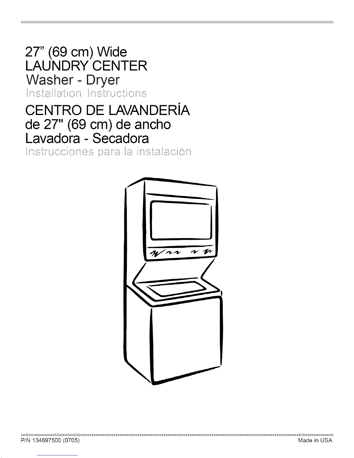
27" (69 cm) Wide
LAUNDRY CENTER
Washer- Dryer
CENTRO DE LAVANDERiA
de 27" (69 cm) de ancho
Lavadora - Secadora
\
iii
Page 2
Table Of Contents
SUBJECT PAGE
Pre-lnstallation Requirements ........................................................................................................ 3
Electrical Requirements ................................................................................................................. 3
Water Supply Requirements ............................................................................................................ 3
Drain Requirements ...................................................................................................................... 3
Exhaust System Requirements ................................................................................................... 4
Gas Supply Requirements ............................................................................................................. 5
Location ................................................................................................................................. 5
Rough-In Dimensions ..................................................................................................................... 6
Mobile Home Installation .............................................................................................................. 7
Unpacking ........................................................................................................................ 7
Electrical Installation ..................................................................................................................... 8
Grounding Requirements ................................................................................................................ 8
3 & 4-Wire Connections .................................................................................................................. 9
Installation ................................................................................................................................. 10-11
Replacement Parts ..................................................................................................................... 11
Espahol ...................................................................................................................................... 12-20
Laundry Center Safety
Before beginning installation, carefully read these instructions. This will simplify the installation
and ensure the laundry center is installed correctly and safely. Leave these instructions near the
laundry center after installation for future reference.
NOTE: The electrical service to the laundry center must conform with local codes and ordinances and the
latest edition of the National Electrical Code, ANSI/NFPA 70, or in Canada, the Canadian Electrical Code,
CSA C22.1
NOTE: The gas service to the laundry center must conform with local codes and ordinances and the latest
edition of the National Fuel Gas Code ANSI Z223.1/NFPA 54, or in Canada, the Canadian Natural Gas and
Propane Installation Code, CSA B149.1.
NOTE: The laundry center is designed under ANSI Z21.5.1 or ANSI/UL 2158- CAN/CSA C22.2 No. 112
(latest edition) for HOME USE only. This laundry center is not recommended for commercial applications
such as restaurants or beauty salons, etc.
For your safety the information in this manual must be followed to minimize the risk of
fire or explosion or to prevent property damage, personal injury or loss of life.
- Do not store or use gasoline or other flammable vapors and liquid in the vicinity of this or any
other appliance.
- WHAT TO DO IF YOU SMELL GAS
o Do not try to light any appliance.
Do not touch any electrical switch; do not use any phone in your building.
Clear the room, building or area of all occupants. Immediately call your gas supplier from a
neighbor's phone.
Follow the gas supplier's instructions.
If you cannot reach your gas supplier, call the fire department.
Installation and service must be preformed by a qualified installer, service agency or the gas supplier.
2
Page 3
PRE-INSTALLATION REQUIREMENTS
Tools and Materials Required for Installation:
1. Phillips head screwdriver.
2. Channel-lock adjustable pliers.
3. Carpenter's level.
4. Flat or straight blade screwdriven
5. Duct tape.
6. Rigid or flexible metal 4 inch (10.16 cm) duct.
7. Vent hood.
8. Pipe thread sealer (Gas).
9. Ratchet with 3/8 inch (0.96 cm) socket.
ELECTRICAL REQUIREMENTS
ELECTRICLaundry Center ]
Circuit- Individual 30 amp branch circuit fused with 30 amp
minimum time delay fuses or circuit breakers.
POWER SUPPLY- 3-wire or 4-wire, 240 volt, single phase, 60
Hz, Alternating Current.
POWER SUPPLY CORD KIT- The laundry center MUST employ
a 3-condutor power supply cord NEMA 10-30 type SRDTrated
at 240 volt AC minimum, 30 amp, with 3 open end spade lug
connectors with upturned ends or closed loop connector OR a
4-condutor power supply cord NEMA 14-30 type SRDTor ST(as
required) rated at 240 volt AC minimum, 30 amp, with 4 open
end spade lug connectors with upturned ends or closed loop
connectors and marked for use with clothes dryers. If being
installed in a new branch circuit installation, manufactured
(mobile) home, recreational vehicle or area which prohibits
grounding through the neutral conductor, the laundry center
MUSTemploy a 4-condutor power supply cord NEMA 14- 30
type SRDTor ST (as required) rated at 240 volt AC minimum,
30 amp, with 4 open end spade lug connectors with upturned
ends or closed loop connectors and marked for usewith clothes
dryers. See ELECTRICAL CONNECTIONS. (Canada - 4-wire
power supply cord is installed on laundry center).
OUTLET RECEPTACLE- NEMA 10-30R (3-wire) receptacle or
NEMA 14- 30R (4-wire) receptacle to be located so the power
supply cord isaccessiblewhen the laundry center isin an installed
position.
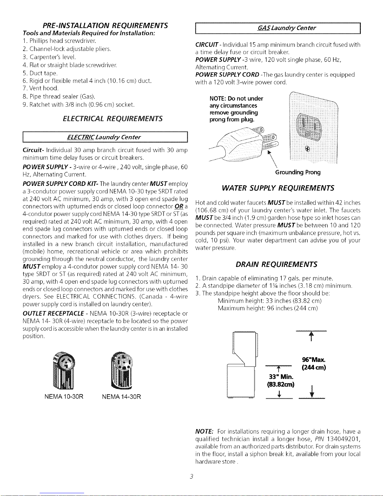
I GASLaundry Center ]
CIRCUIT- Individual 15 amp minimum branch circuit fused with
a time delay fuse or circuit breaker.
POWER SUPPLY-3 wire, 120 volt single phase, 60 Hz,
Alternating Current.
POWER SUPPLY CORD -The gas laundry center is equipped
with a 120 volt 3-wire power cord.
NOTE:Do not under
any circumstances
remove grounding
prong from plug.
\
Grounding Prong
WATER SUPPLY REQUIREMENTS
Hot and cold water faucets MUST be installed within 42 inches
(106.68 cm) of your laundry center's water inlet. The faucets
MUSTbe 3/4 inch (1.9 cm) garden hose type soinlet hoses can
be connected. Water pressure MUST be between 10and 120
pounds per square inch (maximum unbalance pressure, hot vs.
cold, 10 psi). Your water department can advise you of your
water )ressure.
DRAIN REQUIREMENTS
1. Drain capable of eliminating 17 gals. per minute.
2. A standpipe diameter of 11Ainches (3.18 cm) minimum.
3. The standpipe height above the floor should be:
Minimum height: 33 inches (83.82 cm)
Maximum height: 96 inches (244 cm)
t
NEMA 10-30R NEMA 14-30R
96"Max,
---T--'- (244 cm)
33" Min.
(83.82cm)
NOTE: For installations requiring a longer drain hose, have a
qualified technician install a longer hose, PIN 134049201,
available from an authorized parts distributor. Fordrain systems
in the floor, install a siphon break kit, available from your local
hardware store.
Page 4

EXHAUST SYSTEM REQUIREMENTS
Use only 4 inch (10.16 cm) diameter (minimum)
flexible metal duct and approved vent hood which has a
swing-out damper(s) that opens when the dryer is in
operation. When the dryer stops, the damper(s)
automatically closes to prevent drafts and the entrance
of insects and rodents. To avoid restricting the outlet,
maintain a minimum of 12 inches (38.5 cm) clearance
between the vent hood and the ground or any other
obstruction.
The following are specific requirements for
proper and safe operation of your laundry center. Failure to
follow these instructions can create excessive drying times
and fire hazards.
Do not use plastic flexible duct or metal foil to
exhaust the dryer. Excessivelint can build up inside the exhaust
system and create a fire hazard and restrict air flow. Restricted
air flow will increase drying times. If your present system is
made up of plastic duct or metal foil duct, _lace it with a rigid
or flexible metal duct. Ensure the present duct is free of any
lint prior to installing laundry center dryer duct.
iii i i i
INCORRECT
Do not allow combustible materials (for
example: clothinq,draperies/curtains, paper) to come in contact
with the exhaust system. The dryer MUSTNOT be exhausted
into a chimney, a wall, a ceiling, or any concealed space of a
building which can accumulate lint, resulting in a fire hazard.
Do not exceed the lenqth of duct pipe or
number of elbows allowed in the" EXHAUST DUCT LENGTHS"
chart. Lint car/accumulate in the system, plugging the system
and creating a fire hazard, aswell as increasing drying times.
Do not screen the exhaust ends of the vent
system, nor use any screws or rivets to assemble the exhaust
svstem. Lint can become caught in the screen, on the screws or
rivets, clogging the exhaust system and creating a fire hazard
aswell asincreasing drying times. Usean approved vent hood
to terminate the duct outdoors, and seal all joints with duct
tape. All male duct pipe fittings MUSTbe installed downstream
with the flow of air.
Explosion hazard. Do not install the laundry
center where qasoline or other flammables are kept or stored.If
the laundry center isinstalled in a garage, it must be aminimum
of 18 inches (45.7 cm) above the floor. Failure to do so can
result in death, explosion, fire or burns. The exhaust system
back pressure MUST not exceed 0.6 inches(1.52 cm) of water
column, measured with an inclined manometer at the point the
exhaust connects to the dryer. The exhaust system should be
inspected and cleaned a minimum of every two years with
normal usage. The more the dryer is used, the more often you
should check the exhaust system and vent hood for proper
operation.
The maximum length of the exhaust system depends upon the
type of duct used, number of elbows and type of exhaust hood.
If the dryer is not exhausted outdoors some
fine lint will be expelled into the laundry area. An accumulation
of lint in any area of the home can create a health and fire
hazard. The dryer exhaust system MUST be exhausted to
the outside of the dwelling!
The maximum length for both rigid and flexible duct is shown in
the chart below.
EXHAUST DUCT LENGTHS
EXHAUST HOOD TYPE
Number
of 90°
Turns
\,
4"
10.2C 4)
MAXIMUM LENGTH OF 4-INCH (10.2 CM)
DIAMETER RIGID METAL DUCT
0
1
2
3
MAXIMUM LENGTH OF 4-INCH (10.2 CM)
0
1
2
3
56 ft. (17.07 m)
46 ft. (14.02 m)
34ft. (10.36 m)
32 ft. (9.75 m)
DIAMETER FLEXIBLE METAL DUCT
30ft. (9.14 m)
22 ft. (6.7 m)
16 ft. (4.88 m)
10 ft. (3.05 m)
Louvered
_25"
(6.
42 ft.
(12.8 m)
36 ft.
(10.97 m)
28 ft.
<8.53 m>
18 ft.
(5.48 m)
22 ft. (6.7 m)
14ft. (4.27 m)
10 ft. (3.05 m)
5ft. (1.5 m)
4
Page 5

The laundry center may be exhausted four (4) ways with rear
flush installation:
1. Straight back
2. Down (8 inch [20.32 cm] length of 4 inch [10.16 cm] rigid
duct and 1 elbow down)
3. Left(8 inch [20.32 cm] length of 4 inch [10.16 cm] rigid
duct, 1 elbow down and 1 elbow left)
4. Right (8 inch [20.32 cm] length of 4 inch [10.16 cm] rigid
duct, 1 elbow down and 1 elbow right)
To exhaust up, add an 11 inch (27.94 cm) length of standard 4
inch (10.16 cm) diameter duct and a 90° elbow. The unit will
be positioned about 4Y2inches (11.43 cm) away from the wall
(flush to wall exhausting may bedone by going below the dryer
then sideways).
An exhaust hood positioned
to line up with the dryer
exhaust can be installed
directly through the outside
wall. To exhaust to the side
or down, add an 8 inch
(20.32 cm) length of standard
4 inch (10.16 cm) diameter
duct and a 90° elbow.
GAS SUPPLY REQUIREMENTS
1.Installation MUSTconform with local codes, or in the absence
of local codes, with the National FuelGas Code, ANSI Z223.1
(latest edition) or in Canada, the current AN/CGA B149.
2.The gas supply line should be of 1/2 inch (1.27 cm) pipe.
3.If codes allow, flexible metal tubing may be used to connect
your dryer to the gas supply line. The tubing MUST be
constructed of stainless steel or plastic-coated brass.
4.The gas supply line MUST have an individual shutoff valve.
5.A 1/8 inch (0.32 cm) N. RT.plugged tapping, accessible for
test gage connection, MUST be installed immediately
upstream of the gas supply connection to the dryer.
6.The dryer and its individual shutoff valve MUST be
disconnected from the gas supply piping system during any
pressure testing of the gas supply piping system at test
pressures equal to or less than 1/2 psig (3.45 kPa).
7.The dryer MUSTbe isolated from the gassupply piping system
by closing its individual manual shutoff valve during any
pressuretesting of the gas supplypiping systemattest pressures
equal to or less than 1/2 psig (3.45 kPa).
LOCATION OF YOUR LAUNDRY CENTER
DO NOT INSTALL YOUR LA UNDRY CENTER:
1.In an area exposed to dripping water or outside weather conditions.
2.In an area where it will come in contact with curtains or drapes.
3.On carpet. Floor MUSTbe solid with a maximum slope of 1 inch (2.54 cm).
INSTALLATION IN RECESSOR CLOSET
1.A laundry center installed in a bedroom, bathroom, recessor closet, MUSTbe exhausted outdoors.
2.No other fuel burning appliance shall be installed in the same closet asthe Gas laundry center.
3.Your laundry center needs the spacearound it for proper ventilation.
DO NOT INSTALL YOUR LAUNDRY CENTER IN A CLOSET WITH A SOLID DOOR.
4.A mirfimum of 120 square inches (774.2 square cm) of opening, equally divided at the top and bottom of the door, isrequired.
Air openings are required to be unobstructed when a door isinstalled. A Iouvered door with equivalent air openings for the full
length of the door is acceptable.
5.The following illustrations show minimum clearance dimensions and air openings for proper operation in a recess or closet
installation.
' 60 SQ. IN.
(387.1 SQ. CM)
0 IN.
(0 CM)_
DRYER
60 SQ. IN.
(387.1 SQ. CM)
T
60 SQ. IN.
(387.1 SQ. CM)
Closet Door
WAS.E.
60 SQ. IN.
(387.1 SQ. CM)
Page 6

_U
m_
_S
L--J
m_
_u
II
Zt_
m_
o
Page 7

MOBILE HOME INSTALLATION
1.Dryer MUST be exhausted outside (outdoors, not beneath the mobile
home) using metal ducting that will not support combustion. Metal
ducting must be4 inches (10.16 cm) in diameter with no obstructions.
Rigid metal duct is preferred.
2.If dryer isexhausted through the floor and area beneath the mobile
home is enclosed, the exhaust system MUSTterminate outside
the enclosure with the termination securely fastened to the mobile
home structure.
3.Refer to page 3 for other important venting requirements.
ii i
4.When installing a gas dryer into amobile home, a provision must be
made for outside make up air. Thisprovision is to be not lessthan twice
the area of the dryer exhaust outlet.
_iiiiiiiiiiiiiiiiiiiiiiiiiiiiiiiiiiiiiiiiiiiiiiiiiiiiiiiiiiiiiiiiiiiiiiiiiiiiiiiii
5.Installation MUSTconform to current Manufactured Home Construction
& Safety Standard (which is a Federal Regulation Title 24 CFR-Part 32-
80) or when such standard is not applicable, with American National
Standard for Mobile Homes. In Canada, the CSA Z240 is applicable.
_1__ The laundry center is designed under ANSI Z 21.5.1for HOME USE only.
UNPACKING
1. Using the four shipping carton corner posts (two on each
side), carefully lay the laundry center on its left side and
remove foam shipping base.
Excessive weight. Use two or more people
to move Laundry Center.
2. Using a ratchet with 3/8 inch (0.96 cm) socket, remove the
mechanism shipping bolt and plastic spacer block from the
center of the base.
NOTE: If the laundry center is to be transported at a later
date, the tub blocking pad, shipping bolt, and plastic
spacer block should be retained.
3. Return laundry center to an upright position.
4. Remove:
(a) foam tub blocking pad.
(b) foam shipping blocks from rear of unit.
(c) tape from dryer door.
(d) foam dryer support pads.
(e) inlet hoses.
(f) enclosure package.
5. From the back of the washer, remove the wire shipping
clips securing the drain hose and power cord (if equipped).
Plastic clamps secure the drain hose to the right side of
the washer backsheet. These clamps form a standpipe to
prevent water syphoning. DO NOT REMOVE THESE
CLAMPS.
6. Carefully move the laundry center to within 4 feet (1.22 m)
of the final location to begin the installation.
iiiiiiiiiiiiiiiiiiiiiiiiiiiiiiiiiiiiiiiiiiiiiiiiiiiiiiiiiiiiiiiiiiiiii
PLASTICSPACER
SHIPPING
BOLT
FOAM
SHIPPING
PAD
CARTON CORNER POSTS
(IF EQUIPPED)
DRAIN HOSE
Page 8

ELECTRICAL INSTALLATION
GROUNDING REQUIREMENTS
I
_The following are specific requirements for
proper and safe electrical installation of your laundry center.
Failure to follow these instructions can create electrical shock
and/or a fire hazard.
_This appliance MUST be properly qrounded.
Electrical shock can result if the laundry center is not properly
grounded. Follow the instructions in this manual for proper
grounding.
laundry center. Some extension cords are not designed to
withstand the amounts of electrical current this laundry center
utilizes and can melt, creating electrical shock and/or fire hazard.
Locate the laundry center within reach of the receptacle for the
length power cord to be purchased, allowing some slack in the
cord. Refer to the pre-installation requirements in this manual
for the proper power cord to be purchased.
installed onto power cord. If the strain relief isnot attached, the
cord can be pulled out of the laundry center and can be cut by
any movement of the cord, resulting in electrical shock.
ALL ELECTRICLaundry Centers
Do not use an extension cord with this
A U.L approved strain relief must be
i Non-CanadianELECTRICLaundryCenter l
I
Improper connection of the equipment
grounding conductor can result in a risk of electrical shock.
Check with a licensedelectrician if you are indoubt asto whether
the appliance isproperly grounded.
Fora qrounded, cord-connected laundry center:
1. The laundry center MUST be grounded. In the event of
malfunction or breakdown, grounding will reduce the risk of
electrical shock by a path of least resistance for electrical
current.
.
If your laundry center is equipped with a power supply cord
having an equipment-grounding conductor and agrounding
plug, the plug MUSTbe plugged into an appropriate, copper
wired receptacle that is properly installed and grounded in
accordance with all local codes and ordinances. If in doubt,
call a licensed electrician. Do not modify plug provided
with the appliance.
For a permanently connected laundry center:
The laundry center MUST be connected to a grounded metal,
permanent wiring system;or an equipment grounding conductor
MUST be run with the circuit conductors and connected to the
equipment-grounding terminal or lead on the appliance.
I
Canadian ELECTRICLaundry Center
1
Do not use an aluminum wired receptacle
with a copper Wired power cord and plug (or vice versa). A
chemical reaction occurs between copper and aluminum and
can cause electrical shorts.
The proper wiring and receptacle is a copper wired power
cord with a copper wired receptacle OR aluminum wired
power cord with an aluminum wired receptacle.
NOTE: Laundry centers operating on a 208 volt power supply
will have longer drying times than laundry centers operating on
a 240 volt power supply.
_lmproper connection of the equipment
grounding conductor can result in a risk of electrical shock.
Check with a licensed electrician if you are in doubt as to
whether the appliance is properly grounded.
Fora grounded cord connected laundry center:
1. The laundry center MUST be grounded. In the event of
malfunction or breakdown, grounding will reduce the risk of
electrical shock by providing a path of least resistance for
the electrical current.
.
Since your laundry center is equipped with a power supply
cord having an equipment-grounding conductor and a
grounding plug, the plug MUST be plugged into an
appropriate outlet that is properly installed and grounded in
accordance with all codes and ordinances. If in doubt, call a
licensed electrician.
ALL GASLaundry Centers
1.The laundry center is equipped with a three-prong (grounding)
plug for your protection against shock hazard and should be
plugged directly into a properly grounded three-prong
receptacle. Do not cut or remove the grounding prong from
the plug.
i
Page 9

ELECTRICAL CONNECTIONS
FOR A 3-WIRE SYSTEM
ELECTRICAL CONNECTIONS
FOR A 4-WIRE SYSTEM
i NON-G4NAD/ANEZECTR/CLaundry Center
1. Remove the screw securing the
terminal block accesscover to
the rear panel and remove cover.
2. Install a U.L approved strain
relief connector in the entry
hole on the back panel.
3. Insert a NEMA 10-30 Type SRDT,
U.L approved power cord through the strain relief.
4. Attach the power cord neutral (central wire) conductor to
the silver colored center terminal on the terminal block.
Tighten the screw securely.
GREEN GROUND SCREW
NEUTRAL
GROUND
WIRE
SILVER TERMINAL
J
l
1.
NEUTRAL
GROUND
WIRE
NON-CANAD/ANELECTR/CLaundry Center
Remove the screw securing the
terminal block access cover to the
rear panel and remove cover.
.
Install a U.L approved strain relief
connector inthe entry hole on the
back panel.
.
Remove the neutral ground wire from the green ground
screw located above the termial block.
GREEN GROUND GREEN
SCREW CONDUCTOR SILVER TERMINAL
TERMINAL BLOCK
BLACK
WHITE
]
5. Attach the remaining two power cord outer conductors to
the outer brasscolored terminals on the terminal block.
Tighten both screwssecurely.
6. Tighten the screws securing the cord restraint against the
power cord.
7. Reinstall the terminal accesscover.
RED _
STRAIN
RELIEF
MOUNTING
BRACKET,
POWER CORD
.
Insert a NEMA 14-30 Type STor SRDT,U.L approved power
cord through the strain relief.
.
Attach the green power cord ground wire to the cabinet
with the green ground screw.
.
Attach the white (neutral) wire from the power cord and the
neutral ground wire from the appliance harnessto the silver
colored center terminal on the terminal block. Tighten the
screw securely.
.
Attach the red and black wires from the power cord to the
outer brass-colored terminals on the terminal block. Tighten
both screws securely.
.
Tighten the screws securing the cord restraint firmly against
the power cord.
9. Reinstall the terminal block access cover.
Page 10

INSTALLATION
1. Run somewater from the hot and cold faucets to flush the c.
water lines and remove particles that might clog up the
water valve screens, d.
2. Check inlet hosesto ensure the rubber washers are installed
in each end.
3. Carefully connect the inlet hosesto the water valve (on the
left sideof the washer cabinet), tighten by hand, then tighten
another 2/3 turn with pliers.
_0 NOT CROSS THREAD OR
0 VERTIGHTEN THESE CONNECTIONS.
4. Determine which water faucet is the HOT water faucet
and carefully connect the bottom inlet hose to the HOT
water faucet, tighten by hand, then tighten another 2/3
turn with pliers. Carefully connect the top inlet hose to the
COLD water faucet, tighten by hand, then tighten another
2/3 turn with pliers.
DO NOT CROSSTHREADOR OVERTIGHTEN
THESE CONNECTIONS.
Open the shutoff valve in the gassupply line.
Testall connections by brushing on a soapy water solution.
NEVER TESTFOR GASLEAKS WITH AN OPEN FLAME.
.
Form a " U " shape on the end of the drain hose with the
hose pointed toward the drain. Placethe formed end in a
laundry tub or a standpipe and secure with a cable tie
provided in the enclosure package.
WATERWILLSYPHON FROM THEWASHERIFTHEABOVE
INSTRUCTIONS ARE NOT FOLLOWED.
Turn the water on and check for leaks at both connections.
5. Carefully move the laundry center to its final location.
6. To ensure the laundry center is level and solid on all four
legs, tilt the laundry center forward so the rear legsare off
the ground. Gently set the laundry center back down to
allow the rear legs to self adjust. Placea level on top of the
washer. Check it side to side, then front to back. Screw
the front leveling legs up or down to ensure the laundry
center is resting solid on all four legs (no rocking of the
laundry center should exist).
NOTE: Keep the leg extension at a minimum to prevent
excessivevibration.
7. GAS CONNECTION (Gaslaundry centers only)
a. Remove the shipping cap from gas pipe at the rear of the
dryer.
NOTE: DO NOTconnect the laundry center to L.Rgasservice
without converting the gasvalve. An L Rconversion kit must
be installed by a qualified gas technician.
b. Connect a 1/2 inch (1.27 cm) I.D. semi-rigid or approved
pipe from the gassupply line to the 3/8 inch (0.96 cm) pipe
located on the back of the dryer. Usea 1/2 inch (1.27 cm)
to 3/8 inch (0.96 cm) reducer for the connection. Apply an
approved thread sealer that is resistant to the corrosive
action of liquefied gaseson all pipe connections.
Tie_
9. Remove the two (2) screws securing the dryer front access
panel to the dryer cabinet. Lift the panel until the tabs can
be disengaged from the cabinet. Remove the panel and set
aside.
Access
Panel
Screws
Page 11

REPLACEMENT PARTS
10. Connect the exhaust duct to outside duct work. Use duct
tape to seal all joints.
11. Plug the power cord into a grounded outlet.
NOTE: Check to ensure the power is off at a circuit breaker/
fuse box before plugging the power cord into an outlet.
12. Turn on the power at a circuit breaker/fuse box.
_Before operating the dryer, make
sure the dryer area is clear and free from
combustible materials, gasoline, and other
flammable vapors. Also see that nothing (such as
boxes, clothing, etc.) obstructs the flow of
combustion and ventilation air.
13. Reinstall the dryer front access panel.
14. Runthe washer and dryer though acycle.Check for proper
operation.
NOTE: On gas dryers, before the burner will light, it is
necessary for the gas line to be bled of air. If the burner
does not light within 45 seconds the first time the
dryer is turned on, the safety switch will shut the
burner off. If this happens, turn the timer to "OFF"
and wait 5 minutes before making another attempt to
light.
If replacement parts are needed for your laundry center, contact
the source where you purchased your laundry centen
_ Destroy the carton, plastic bags, and metal
band after the laundry center is unpacked. Children might use
them for play. Cartons covered with rugs, bedspreads, or plastic
sheets can become airtight chambers causing suffocation. Place
all materials inagarbage container or make materials inaccessible
to children.
Label all wires prior to disconnection when
servicing controls. Wiring errors can cause improper and
dangerous operation. Verify proper operation after servicing.
The instructions in this manual and all other
literature included with this laundry center are not meant to
cover everypossiblecondition and situation that may occur-.Good
safe practice and caution MUST be applied when installing,
operating and maintaining any appliance.
Maximum benefits and enjoyment are achieved when
all the Safety and Operating instructions are understood
and practiced as a routine with your laundry tasks.
15. If your laundry center does not operate, please review the
"Avoid Service Checklist" located in your Owner's Guide
before calling for service.
16. Placethese instructions ina location near the laundry center
for future reference.
NOTE: A wiring diagram is located behind the dryer front
access panel.
10
Page 12

Indite
MA TERIA PAGINA
Requerimientosdeinstalaci6n preliminares ..............................................................................................................
Requerimientos el_ctricos .........................................................................................................................................
Requerimientos delsuministro deagua ...................................................................................................................
RequerimientosdedesagOe ..................................................................................................................................... 14
Requerimientos del sistema de escape.............................................................................................................. 14-15
Requerimientos del suministro de gas.................................................................................................................... 15
Ubicaci6n ............................................................................................................................................................... 15
Dimensionespara lainstalaci6n ............................................................................................................................. 16
Instalaci6n en casasm6viles .................................................................................................................................. 17
Desembalaje.......................................................................................................................................................... 17
Instalaci6n el_ctrica ............................................................................................................................................... 18
Requerimientos para la puesta atierra .................................................................................................................. 18
Conexi6nes el_ctricas- trifilaresy tetrafilares ................................................................................................... 18-19
Instalaci0n ........................................................................................................................................................ 19-20
Repuestos.............................................................................................................................................................. 20
SEGURIDAD de CENTRO DE LAVANDARIA
Antes de comenzar la instalaci6n, lea cuidadosamente estas instrucciones. Esto simplificar_i la instalaci6n y
asegurar_i que la secadora se instale correctamente y de manera segura. Despu_s de completar la instalaci6n,
coloque estas instrucciones cerca de la secadora para referencia futura.
NOTA: Laalimentacion electrica para la secadora deber_qcumplir con los c6digos y reglamentos locales y con
la 01tima edici6n del C6digo El_ctrico Nacional, ANSI/NFPA 70 o en Canada1 CSA C22.1 C6digo El_ctrico
Canadiense, Parte 1.
NOTA: Laalimentaci6n de gas para la secadora deber_i cumplir con los c6digos y reglamentos locales y con la
01tima edici6n del C6digo Nacional para Gases Combustibles, ANSI Z223.1 o en Canada1CAN/CGA B149.12.
NOTA: La secadora est_qclasificada para USO DOMESTICO solamente, de acuerdo con la norma ANSI Z 21.5.1
o ANSI/UL 2158 - CAN/CSA C22.2 No. 112 (las 01timas edici6nes). Esta secadora no se recomienda para uso
commercial tal como en restaurantes, salones de belleza, etc.
Parasuseguridad, siga las instrucciones contenidas en este manual afin de reducir
a un minimo los riesgos de incendio o explosi6n o para evitar dahos materiales, lesiones personales o la
muerte.
- No almacene ni utilice gasolina u otros vapores y liquidos inflamables en la proximidad de _ste o de
cualquier otro artefacto el_ctrico.
- QUE DEBE HACER S! PERCIBE OLOR A GAS
o No trate de encender ning0n artefacto el_ctrico.
No toque ning0n interruptor el_ctrico; no use ning0n tel_fono en su edificio.
Haga salir a todos los ocupantes de la habitaci6n, del edificio y del lugar.
Llame a su proveedor de gas desde el teldono de un vecino. Siga las instrucciones del proveedor de
gas.
Sino Iogra comunicarse con su proveedor de gas, Ilame al departamento de bomberos.
La instalaci6n y el servicio de mantenimiento debe de realizarlos un instalador calificado, la agencia
de servicios o el proveedor de gas.
12
Page 13

REQUERIMIENTOS DE iNS TALA CION
PRELIMINARES
Herramientas y materiales necesarios para la instalaciOn:
I. Destornillador Phillips
2. Alicates universales
3. Nivel de carpintero
4. Destornillador para tornillo de cabeza plana o recta
5. Cinta paraductos
6. Ducto metalico rigido o flexible de 4" (10,2 cm)
7. Caperuza de salida
8. Sellador de tuberias (gas)
9. LLavede tubo de 3/8 de pulgada (0,96 cm).
REQUERIMIENTOS ELECTRICOS
i Centre de/avander/a a GAS ]
CIRCUITO - Circuito individual derivado de 15 amp minimo, con
fusibles de retardo maximo o disyuntor.
ALIMENTACION ELECTRICA - Corriente alterna, monof_isica,
60 Hz, 120 voltios, trifilar.
CORDONELECTRICO - La secadora est,1equipada con un cordon
electrico trifilar para 120 voltios.
NOTA: No saque por
ningun motivo la espiga
de puesta a tierra del
enchufe.
I Centro de/avander/a ELLeCTRICAS i
CIRCUITO - Circuito derivado individual de 30 amperes, con
fusibles de 30 amp. del tipo de retardo minimo o disyuntores.
ALIMENTACIONELECTRICA - Corriente alterna, monofasica,60
Hz,240 voltios; trifilar. (Canada- 240 voltios, monofasico, 60 Hz,
corrienta alterna.)
CORDONEL_'CTRICO- EnlasecadoraseDEBEusar un cordon
elOctricotrifilar NEMA 10-30 tipo SRDTpara un voltaje nominal
minimo de240 voltiosCA,30 amp, con3 conectoresdehorquillas
con terminales abiertos y extremos dirigidos hacia arriba o
conectores de anillo cerrado y marcados para usoen secadoras
de ropa. Sisiendo instalado enuna nueva instalaciOndel circuito
del rama,un vehiculo casero,recreacional (mOvil)manufacturado
o un area que prohiben el poner a tierra a traves del conductor
neutral, seDEBEutilizar un cordon el_ctrico tetrafilar NEMA 14-
30 tipo SRDToST(como seanecesario) para un voltaje nominal
minimo de 240 voltios CA, 30 amp con4 conectores dehorquillas
con terminales abiertos y extremos dirigidos hacia arriba o
conectores de anillo cerrado y marcados para usoen secadoras
de ropa.
VerCONEXiONES ELECTRICAS PARA SISTEMAS
TETRAFILARES.
(Canada - un cordon de suministro de energia de 4alambres es
instalado en lasecadora.)
TOMACORRIENTE- Eltomacorriente NEMA 10-30R debe estar
ubicado de maneraque el cordon el_ctrico Ileguehasta61cuando
lasecadora est_instalada. (Canada- receptaculo NEMA 14-30R.)
Espiga de I a tierra
REQUERIMENTOS DE SUMINISTRO DE AGUA
LasIlaves del agua caliente yfria DEBER,4Nser instaladas a no
mas de 42 pulgadas (106,68 cm) de la entrada de agua de su
centro de lavanderia. La boca DEBEser de 3/4 pulgada (1,9
cm) de diametro para que las mangueras dejardin puedan ser
conectadas. LapresiOn de agua DEBE SERentre I0 y 120lOs./
pulg.2 (la maxima diferencia entre la presiOn no equilibrada
del agua caliente yfria es 101bs./pulg.2) Lacompaflia de agua
potable puede informarle sobre le presiOndel agua.
REQUERIMINTOS DE DESAGOE
1. Capacidad para desaguar 17 galones por minuto.
2. Diametro de la toma de agua: 1-1/4 pulgadas (3,16) como
minimo.
3. Altura de la toma de agua sobre el piso:
Altura minima:
33 pulgadas (83,82 cm)
Altura maxima:
96 pulgadas (244 cm)
t
(244cm)
1'
33" Mi..
(83°82cm)
NEMA 10-30R
NEMA 14-30R
______k__
NOTA : Paralasinstalacionesquerequieranuntubodemas
largo, pida a un tOcnico capacitado que instale un tubo mas
largo, P/N 131461201, disponsible en los disribuidores
autorizados de piezasde repuesto. Paralossistemas dedrenaje
en el piso, instale un uego para detener la acciOn de sifOn,
disponsible de una ferreteria local.
13
Page 14

REQUERIMIENTOS DEL SISTEMA DE ESCAPE
Utilice solamente ductos metalicos, rigidos o flexibles de 4"
(10,2 cm) de diametro (minimo) y una caperuza de salida deuso
aprobado, conregistrosque girenhaciaafuera queseabren cuando
lasecadora seencuentra enfuncionamiento. Cuando lasecadora
sedetiene, los registros secierran automaticamente para evitar
lascorrientes deaire yla entrada de insectosyroedores. Paraevitar
obstruir la salida,mantenga una altura libre minima de 12 "(30,5
cm) entre la caperuza de salida y el piso o entre cualquier otra
obstrucci6n.
Los siguientes requerimientos son
especificos para el fundonamiento correcto y seguro de su
secadora. Elincumplimiento de estas instrucciones puede
causar prolongacion excesiva del tiempo de secado y riesgos
de incendio.
[] No use caho flexible de plastico ni papel metalizado para
desagotar la secadora.
Sepuede acumular un excesode pelusasenelsistemade escape,
crear un riesgoyobstruir elflujo de aire. Larestricci6n delflujo del
aire prolongara eltiempo desecado.Sisu sistemadeescapeactual
tiene ductos de plastico o de laminas metalicas delgadas,
reemplacelo con un ducto metalico ricido oflexible.Asegurese
de que los ductos existentes no tengan pelusas antes de
instalar el ducto de la secadora.
INCORRECT
F :i¸'i!i;i¸ii!iiiii!ii¸'i¸i¸iiiiiiiiiiiiiiiiiiiiiiiiiiiii_ii!i___i!ii_iiiiiiiiiiiiiiiiiiiiiiiiiiiiiiiiiiiiiiiiiiiiiiiiiiiii
[] No permita que losmateriales combustibles (por ejemplo: la
ropa, cortinas/cortinajes, papel)tenqan contacto con losductos.
El escapede la secadora NO DEBE dirigirse hacia el interior de
una chimenea, haciauna pared,haciaelcielo rasoo haciacualquier
otro espacio reducido del edificio, donde puede ocurrir
acumulaci6n de pelusasyconstituir un peligro de incendio.
[] ExcederlaIongitud del conducto riaido olosn0merosdecodos
permitidosen Iosdiaaramas "LARGOM,4,XIMO" puededisminuir
la capacidad de exhaustaci6n del sistema. Obstruir el conducto
puede provocar peligro de incendio, asicomo aumentar eltiempo
de secado.
[] No coloque un filtro en el extremo delescapedel sistema ni
empleetomillos o remachespara ensamblar elsistemadeescape.
Laspelusaspodrian quedar atrapadasenlosfiltros, enIostomillos
o enlos remaches,Iocualobstruiria elsistema de escapey crearia
un riesgo de incendio, asicomo tambi@n prolongaria el tiempo
de secado. Useunacaperuzade salidaadecuada para elextremo
del ducto que salgaalexterior de lavivienday selletodas lasjuntas
con cinta adhesiva para ductos. Todos losaccesorios de tuberia
machos, DEBEN serinstalados aguas abajo del flujo de aire.
Riesgo de explosiSn. No instale la
secadoradonde sequarda qasolinau otrosmaterialesinflamables.
Silasecadoraseinstalaen ungarage, ella debeestarpor Iomenos
18 pulgadas (45,7 cm) por encima del suelo. Elincumplimiento
puede resultar en la muerte, explosi6n, incendio, oquemaduras.
1. LaconstrapresiOn del sistema de escape NO DEBE exceder
0,6 pulgadas (1,52 cm) de columna de agua, medida con
un man6metro inclinado en la conexi6n del ducto de escape
a la secadora.
2. Elsistema de escape debe ser inspeccionado y limpiado
cada 2 ahos como minimo, bajo condiciones de uso
normal. Mientrasm_sseuselasecadora, con mayor
frecuencia deben inspeccionarse el sistema de escape y la
caperuza de salida para verificar su buen funcionamiento.
El largo m_ximo sistema de escape depende del tipo de ducto
que se usa, del nQmero de codos y del tipo de caperuza de
salida. Enlatablasemuestraellargom_ximotantopara
ductos flexibles como rigidos.
LARGO MAXIMO del Conducto Metalico
Rigido de 4" (10,2 cm) de Diametro
TIPO DE CAPERUZADE SALIDA
(Preferido)
\
CORRECT
CORRECT
[] Si el escapede la secadora no sediriqe al exterior, alqunas
pelusas finas seransopladas hacia el recinto donde se efectOael
lavado. Laacumulaci6n de pelusasen cualquier lugar de lacasa,
puede crear un peligro para la salud yun riesgo de incendio, iE/
sistema de escape de la secadora DEBEestar dirigido hacia
el exterior de la vivienda!
(10,2 cm) (6.35 cm)
0 56 pies (17,07 m) 42 pies(12,8 m)
1 46 pies (14,02 m) 36 pies(10,97 m)
2 34 pies (10,36 m) 28 pies (8,53 m)
3 32 pies (9,75 m) 18 pies (5,48 m)
LARGO MAXIMO del Conducto Metalico
Flexible de 4" (10,2 cm) de Diametro
TIPODE CAPERUZA DESALIDA
0 30 pies (9,14 m) 22 pies (5,49 m)
1 22pies (6,71 m) 14 pies (4,27 m)
2 16pie (4,88 m) 10 pies (3,05 m)
3 NO RECOMENDADO
14
Page 15

Se puede colocar el ducto de escape de cuatro (4) maneras
distintas cuando elartefacto estainstalado conel fondo paralelo
con la pared.
I. Derecho hacia arras.
2. Hacia abajo - ducto rigido, 8 pulgadas(20.32 cm)deIongitud
y4 pulgadas (10,16 cm) de diametro & 1 ducto acodado
hacia abajo.
3. Hacia la izquierda - ducto rigido, 8 pilgadas (20,32 cm) de
Iongitud y 4 pulgadas (10,16 cm) de diametro, 1 ducto
acodado hacia abajo y un ducto acodado hacia la derecha.
4. Hacia la derecha - ducto rigido, 8 pulgadas (20,32 cm) de
Iongitud y 4 pulgadas (10,16 cm) de diametro, I ducto
acodado hacia abajo y un ducto acodado hacia la derecha.
Para colocar el ducto de escape hacia arriba, aflada un ducto
de 11 pulgadas (27,94 cm) de Iongitud y de4 pulgadas (10,16
cm) de diametroy un ducto acodado de 90°. El artefacto
debe estar a aproximadamente 4 1/2 pulgadas (11,43 cm) de
la pared (Se puede colocar el ducto de escape paralelo con la
pared pot colocarlo debajo de la secadora y dirigirlo hacia un
lado).
Una caperuza de escape
colocada en forma tal que se
alinie con el escape de la
secadora, puede set instalada
directamente a trav_s de la
pared exterior. Para colocar el
ducto de escape hacia arriba,
aflada un ducto 11 pulgadas
(27,94 cm) de Iongitud y 4
pulgadas (10,16 cm) de
y un ducto acodado de 90° . El
artefacto debe estar a
aproximadamente 4 I/2 pulgadas (11,43 cm) de la pared (se
puede colocar el ducto de escape paralelo con la pared
coloc_ndolo debajo de la secadora y dirigido hacia un lado).
Para permitir el escape lateral o inferior, agregue un ducto de 8
pulgadas (20,32 cm)de largo y4 pulgadas(10,16 cm) dediametro
est_ndar y un codo de 90°.
REQUERIMIENTOS DEL SUMINISTRO DE GAS
1. LainstalaciOn DEBE hacersecumplir con los cOdigos locales o
en ausencia de los mismos, de acuerdo con losestandares del
National Fuel Gas Code(COdigo Nacional para Gases
Combustibles), ANSIZ223. I (la 01tima edition). ParaCanad&
el Estandar CAN/CGA B149 que este en vigor.
2. Latuberia de alimentaciOn de gas debe set de I/2 pulgada
(1,27 cm) de diametro.
3. Siesta permitido pot los codigos locales,sepuede usartuberia
de metal para conectar susecadora a laIinea desuministro de
gas. Latubefia DEBEsetfabricada de acero inoxidable ocobre
recubierto de plastico.
4. Latuberia dealimentaciOn degasDEBEtener una Ilavedecierre
individual.
5. Una toma de 1/8 de pulgada (0,32 cm) N.RT. accesible para
conexiOn del manOmetro de prueba, DEBE set instalada
inmediatamente aguas arriba de laconexiOn de latuberia de
alimentaciOn de gasa la secadora.
6. LasecadoraDEBEserdesconectada del sistema detuberiasde
alimentaciOn de gas durante cualquier ensayo de presiOn del
sistema detubefiasde alimentaciOn degasrealizadoapresiones
de prueba de mas de 1/2 Ibs/pulg.2(3,45 kPa).
7. La secadora DEBE aislarse del sistema de tuberias de
alimentaciOn de gas durante cualquier ensayo de presiOn del
sistema detubefiasde alimentaciOndegas realizadoen ensayos
de presiOn iguales o inferiores a I/2 Ibs/pulg.2(3,45 kPa).
UBICA CION DE SU LA VANDER/A
NO INSTALESU LAVANDERi:
1. En un lugar donde puede haber goteos de agua o quede
expuesta alas inclemencias del tiempo.
2. Enun area donde pueda entrar en contacto con cortinas,
cortinajes o cualquier otra cosa que obstruya el flujo de
combustion yventilaciOn de aire.
3. Sobre alfombras. El piso DEBE set firme con un desnivel
maximo de 1 pulgada (2,54 cm).
INSTALACION DENTRO DEUNNICHO OARMARIO
I. Si lasecadora esinstalada en undormitorio, cuarto de baflo,
nicho o armario, el tubo del escapeDEBEserinstalado hacia
el exterior.
2. No se debe instalar ning0n otro artefacto que queme
combustible en el mismo armario en que esta instalada la
secadora a Gas.
3. La secadora necesita espacio a su alrededor para una
ventilaciOn adecuada.
NO INSTALE LA SECADORA EN UNARMARIO CON PUERTA
MACIZA.
4. Serequiere corno minimo una abertura de 120pulgadas cua-
dradas (774,2 cm2), dividida equitativamente para la parte
superior e inferior de lapuerta. Cuando seinstala unapuerta,
es necesario proveer aberturas para el aire. Una puerta
apersianada con aberturas para el aire en todo ellargo de la
puerta esaceptable.
5. Lassiguientes ilustraci0nesmuestran lasdimensi0nes minimas
de espaciolibre que debe existir paraelbuen funcionamiento
de lasecadora cuando se instalaen un nicho o enun armario.
• 60 Pulg. _
(387.1 SQ. CM)
60 Pulg.2
(387.1 SQ. CM)
PU ERTA DEL ARIVIARIO
0 IN,
(oCM)_
€
i!iiii!!!!ii!ii!iii!iiiiii!iSI
ii_ _ii_
15
Page 16

N_
m U
,,..-_
Z A
m
0
3
t
L-J
t
_t
.L,_
v
0
v
Z_
Wt_ z_
_m
_rZ
,_'rn
Z_
O
t'N_
v
v
16
Page 17

INSTALACION EN CASAS MOVILES
1. Eltubo de escape de la secadora DEBEser instalado hacia el
exterior (El escape debe colocarse en la parte exterior y no
debajo de lacasam6vil.) Debe usarse ducto de metal que no
seacombustible. Elducto de metal debetener cuatro pulgadas
(10,16 era)de diametro y notener obstrucciones. Espreferible
usar ducto de metal que searigido.
2. Siel tubo de escape de lasecadora corre a trav_s del piso yel
area debajo de la casa m6vil es cerrada, el ducto de escape
DEBEterminar fuera delrecinto, con elextremo final asegurado
en contra de la estructura de lacasa m6vil.
3. AI instalar una secadora de gas en una casam6vil, hay que
instalaruna provisi6n deairefresco suplementario. Laprovisi6n
tiene que sermas grande que dosveceselespaciodel escape
de la secadora.
4. Vea las paginas 2 y 3 para otros requisitos importantes de
ventilaci6n.
5. Lainstalaci6n DEBE cumplir con lasestandares aplicables de
la Manufactured Home Construction & Safety Standard -
Estandaresde SeguridadyConstrucciOndeCasasPrdabricadas
(TituIo24 CFR-Parte32-80 del Reglamento Federal)ocuando
dichos estandares no seanaplicables, se deben complir con
los estandares de la American National Standard for Mobile
Homes (Estandares Nacionales Americanas para Viviendas
Moviles). EnCanada se aplica el Estandar CSAZ240.
r_ _'' ' " EstasecadorahasidodisehadaPARA
USO DOMESTICO solamente, de acuerdo con la norma ANSIZ
21.5.1.
DESEMBALA.IE
I. Utilizando lascuatro esquineras de embarque de la caja de
carton (dosacadalado), coloque cuidadosamente lasecadora
sobre el costado izquierdo y saque la base de espuma de
embarque.
Peso excesivo. Senecesitan dos o mas
personas para mover la Lavadora.
2. Utilizando la Ilavede tubo de 3/8 de pulgada (0,96 cm) saque
el perno de embarque y el bloque espaciador de platico del
centro de la base.
NOTA: Si elcentro de lavanderia via set transportada aotto
lugar a otra lugar posteriormente, conserve la espuma
de bloqueo de la tina, el perno de embarque y el
espaciador de pl2stico.
3. Vuelva a colocar elcentro de lavanderia en la posiciOnvertical
Bloque
espaciador de
Perno de
embarque
Bloque de embarque
4. Saque:
(a) la pieza de espuma que bloquea la cavidad;
(b) los bloques de espuma del embalaje de la parte posterior
del aparato;
(c) la cinta de la puerta de la secadora;
(d) las piezas de espuma para apoyar la seadora;
(e) los tubos de entrada de agua;
(f) el paquete.
5. Saque laspinzas metalicas del embalaje de laparte posterior
de la lavadora, que sujetan el tubo de drenaje y el cable
el_ctrico. Hay abrazaderas de plastico que sujetan el tubo
de drenaje en labo derecho del resaldo de la lavadora.
Estasabrazaderas forman una tubeda vertical para prevenir
el sifonaje de agua. NO SAQUE ESTASABRAZADERAS.
6. Con cuidado, mueva el centro de lavanderia a cuatro pies
(1,22 m) de su ubicaciOn definitiva para la instalaciOn final.
Espuma
protectora
de embareque
(si viene el equipo)
Manguera de
desagOe
17
Page 18

INSTALA C!6N ELL'CTRICA
[ TODA S/escentre/avanderia ELECTRICAS ]
Los siguientes requerimientos son
especificos para el funcionamien to correcto y seguro de su
secadora. El incumplimiento de estas instrucciones puede
causar prolongaci6n excesiva del tiempo de secado y riesgos
de incendio.
_._J__ Este artefacto DEBE set puesto a tierra de
manera correcta. Si lalavanderia no esta debidamente puesta a
tierra sepuede producir un choque el_ctrico. Sigalasinstrucciones
indicadas eneste manual para lapuesta atierra enforma correcta.
__ No use un cordon de extension con esta
lavanderia. Algunos cordones deextension no pueden soportar la
cantidad de corriente el_ctrica que utiliza estasecadoray pueden
fundirse, creando un peligro de choque el_ctrico y/o incendio.
Ubique la lavanderia de manera que el cordon el_ctrico Ilegue
hastaeltomacorriente quesevaausar,dejando un poco de holgura
paraelcord0n. ConsultelosrequerimientosdeinstalaciOn
preliminares indicados eneste manual para elcordon el_ctrico que
debeseradquirido.
Sedebe instalar un anclaje aprobado pot el
U.L para elcordon el_ctrico. Sino seutiliza un anclaje parasujetar
el cordon el_ctrico, _ste puede salirse de lalavanderia y cortarse
con cualquier movimiento, resultando en un choque el_ctrico.
No utilice un tomacorriente con cables de
aluminio con un cordon Vun enchufe de cobre (o viceversa). Se
produce una reacciOn quimica entre el cobre y el aluminio que
puede causar cortacircuitos. El cableado y temacorriente
apropiado es un cord6n el_ctrico equipado con conductores
de cobre con un tomacorriente con conductores de cobre.
NOTA: Las lavanderia que operan con un suministro de energia
de 208 voltios usaran mastiempo de secado que aquellas que
operan con un suministro deenergia de 240 voltios.
REQUERIMIENTOS PARA LA PUESTA A TIERRA
Centre de/avanderia ELt CTRICASNo can adien ses
i
LaconexiOn indebida del conductor de puesta
atierra del equipo puede ocasionar un riesgode choque el_ctrico.
Consultecon un electricistaprofesionalsitienealguna duda respecto
a lapuesta a tierra correcta del artefacto.
Parauna secadora puesta atierra con cordon el_ctrico:
I. La lavanderia DEBE set puesta a tierra. En caso de
malfuncionamiento ofalla, la puesta atierra reducira el riesgo
de choque el_ctrico proporcionando un trayecto de menor
resistencia a la corriente electrica.
2. Sisu lavanderiaestaequipada conun cordon elOctricoqueposee
un conductor de puesta a tierra del equipo y un enchufe de
puesta a tierra, dicho enchufe DEBE set conectado a un
tomacorriente adecuado, debidamente instalado y puesto a
tierra de acuerdo con todos loscOdigosy reglamentos locales.
Sitiene alguna duda consulte aun electricista profesional. No
modifique el enchufe proporcionado la apficacion.
Para una lavanderia conectada permanentemente:
I. Lalavanderia DEBEser conectada a un sistema de cableado
metalico permanente, puesto a tierra; o se debe instalar un
conductor de puesta a tierra de equipo junto con los
conductores del circuitoy conectarsealborne depuestaatierra
del equipo o al cable del artefacto.
Centre de/avanderia ELffCTR/CAS canadienses 1
LaconexiOn indebida del conductor de puesta
atierra del equipo puede ocasionar unriesgo dechoque el_ctrico.
Consulte con un electricista profesional si tiene alguna duda
respecto a lapuesta a tierra correcta del artefacto.
Parauna lavanderia puesta atierra, con cordon el_ctrico:
1. La lavanderia DEBE set puesta a tierra.En caso de
malfuncionamiento o falla, lapuestaatierra reducira elriesgo
de choque el_ctrico proporcionando un trayecto de menor
resistencia a la corriente el_ctrica.
Si su lavanderia esta equipada con un cordon el_ctrico que
poseeun conductor de puesta atierra del equipoy un enchufe
de puesta a tierra, dicho enchufe DEBE set conectado a un
tomacorriente adecuado, debidamente instalado y puesto a
tierra de acuerdo contodos los cOdigosyreglamentos locales.
Sitienealguna duda consultea un electricista profesional. No
medifique el enchufe propercienado la aplicaci6n.
l TODOS/os centres/avanderia GAS 1
Estalavenderia estaequipada con unenchufe detres espigas (de
puesta atierra) para protecciOn en contra de choques el_ctricos
ydebe set conectada directamenta en un receptaculo para tres
espigas el cual debe estar puesto atierra. No torte ni elimine la
espiga de puesta a tierra deeste enchufe.
CONEXI6NES ELECTRICASPARA
UN SISTEMA TRIFILAR
Centre de/avanderia ELECTR/CASNo canadienses
J
1.
J
Saque los tornillos que sujetan la cubierta
de accesodel tablero de homes y elsoporte
de montaje del anclaje del cordon, situado
en la esquinasuperior de la parte trasera de
la secadora.
Instaleun anclaje de cable aprobado pot el
U.L, enel orificiodeentradadelcord0n
el_ctrico en el soporte de montaje. Luego
apriete latuerca con los dedos solamente.
Inserteuncordon el_ctricode 30amp,NEMA
10-30 Tipo SRDT,aprobado pot el U.L, a
tray,s del anclaje de cable.
18
a
Page 19

4.Conecteelconductorneutrodelcordonel_ctrico(cablecentral)
albornecentralplateadodeltablerodebornes.Apriete
firmementeeltornillo.
BORNE PLATEADO
TORNILLOpuESTAAVERDE DE _ /
TIERRA
CABLE DE
PUESTAA
TIERRA
NEUTR0
5. Conecte losdos conductores externos restantes del cordon
el_ctrico a los bornes bronceados externos del tablero de
bornes. Apriete firmemente lostornillos.
6. Apriete firmemente lostornillosdel anclaje decahie contra el
cordon el_ctrico.
7. Coloque nuevamente la cubierta del tablero de bornes.
CONEXIONES EL_'CTRICASPARA
UN SISTEMA TETRAFILAR
Centro de/avanderia ELECTR/CASNo canadienses
I. Saquelostornillos quesujetanla cubiertadeaccesodeltablero
de bornesy el soporte de montaje del anclajede cablesituado
en la esquina superior en la parte trasera de la secadora.
2. Instale unanclaje decable aprobado porel U.L, en elorificio
de entrada del cordon elOctrico en el soporte de montaje.
Luego apriete la tuerca con losdedos solamente.
TORNILLO VERDE
DE PUESTA
ATIERRA
CABLE DE
PUESTAA
TIERRA
NEUTRB
ROJO "
CONDUCTOR VERDE DE CORDON
/ ELECTRICO BORNE PLATEADO
_ _ / TABLERO DE
i
3. Desconecte el cable de puesta a tierra neutral del tornillo
verde de puestaatierra situado en laparte superior deltablero
de bornes.
4. Inserte uncordon el_ctricote trafilar de 30amp, NEMA 10-30
Tipo SToSRDT,aprobado por el U.L, atray,s delanclaje de
cable.
5. Conecte el cableverde de puesta atierra del cordon el_ctrico
al gabinete mediante el tornillo verde de puesta atierra.
6. Conecte el conductor blanco (neutro) delcordon el_ctrico y
el cable depuesta atierra neutro del mazo de cables de
lasecadora al borne plateado central del tablero de bornes.
7. Conecte losconductores rojoy negro del cordon el_ctrico a
los bornes bronceados externos deltablero de bornes.
8. Apriete firmemente los tornillos del anclaje de cable contra
el cordon el_ctrico.
9. Coloque nuevamente la cubierta del tablero de bornes.
INS TALA CION
I. Deje correr un poco de agua de lasIlaves de agua caliente
y fria para pilgar las Nneasy eliminar las particulas que pued
en obstriur las rejillas de las %lvulas de agua.
2. Examine los tubos de entrada de agua para asegurarse de
que lasarandelas de caucho est_n instaladas en cada extremo.
3. Conecte con cuidado los tubos de entrada a la %lvula de
agua (en el lado izquierdo de la lavadora), apriete a mano y
luego apriete 2/3 d vuelta con unos alicates.
NO ESTROPEE LA5 ROSCAS NI APRIETE
ESTAS CONEXlONES EXCESIVAMENTE.
4. Determine cual de lasIlavesdeagua esla de agua CALIENTE
y conecte con cuidado el tubo inferior de entrada a la Ilave
de agua CALENTE, apriete a mano y luego apriete 2/3 de
vuelta con unos alicates. Conecte con cuidado el tubo
superior de entrada a la Ilavedeagua FRL4,apriete a mano
y luege apriete 2/3 vuelta con unos alicates
NO ESTROPEE LAS ROSCAS N! APRIETE
ESTASCONEXlONES EXCESIVAMENTE. Abra la Ilavedel agua
y compuebe que no haya fugas en ninguna de lasdos
conexiones.
5. Con cuidado, mueve el centro de lavanderia hasta su
ubicaci6n definitiva para instalaci6n final.
6. Para verificar si el centro de lavanderia esta nivelado y
firmemente asentado sobre lascuatro patas, inclinelo hacia
adelante de modo que las patas posteriors queden en
el aire. Luego vuelva a depositar cuidadosamente la
m_quina para permitir que las patas posteriores seajusten.
Coloque un nivel de carpintero encima de la lavadora.
Atornille o destornille lostornillos nivel de posteriores de la
lavadora
seg0n sea necesario para que el centro de lavanderia quede
firmemente asentado sobre suscuatro patas (no debe haber
movimiento de vaivOn.
NOTA: Mantenga las patas de nivelaciOn al minimo para
prevenir excesiva vibraciOn.
Page 20

7. CONEXIONDELGAS(Secadoras agas solamente)
a. Saque latapa de embarque de la tuberfa de gas de la
secadora situada en la parte trasera.
NOTA: NO conecte la lavanderia al suministro de propano, sin
primero instalar el juego de conversi6n a propano. Eljuego de
conversi6n a propano debe ser instalado por un t@cnicode gas
calificado.
b.Conecte una tuberfa semifigida de 1/2" (1,27 cm) D.I. o
una tubefia aprobada, desde la Ifnea de suministro de
gas a latuberfa de 3/8" (0,96 cm) ubicada en la parte
trasera de la secadora. Utilice un reductor de 1/2" (1,27
cm)a 3/8" (0,96 cm)paralaconexi6n. Aplique unsellador
de roscas de uso aprobado, resistente a lacorrosi6n de
losgases licuados, en todas lasuniones de la tuberia.
c. Abra la valvula de cierre en latuberia de suministro de
gas.
d. Pruebetodaslasconexionesaplicandocon una
escobilla una soluci6n jabonosa.
NUNCA UTILICEUNA LLAMA ABIERTA PARADETECTAR
FUGASDE GAS.
8. Forme una "U" en el extremodeltubo de drenage co el
tubo seflalando hacia el drenaje. Coloque el extremo
formado del tubo de drenaje en lavadero or una tuberfa
vertical y fijelo con susujetacables incluido en el paquete.
10.Conecte elducto de escapealsistemadeescapeexterior. Utilice
cinta para obturar todas asuniones.
1I. Conecte elcord6n el@ctricoaun tomacorriente puesto atierra.
NOTA; AsegOresede que lacorriente est@desconectada en el
disyuntodcaja defusibles, antesdeconectar elcord6n el@ctrico
en el tomacorriente.
12.Conecte la corriente en el disyuntodcaja de fusibles.
Antes de poner en funcionamiento la
secadora, asegOresede quenohaya materiales combustibles,
gasolina y otros vapores inflamables cerca de la secadora.
AdemDsasegOresedeque no hayanada (talcomo cajas,ropas,
etc.) que obstruya el flujo delairede combusti6n y ventilad6n.
13. Vuelva a instalar el panel de acceso delantero de la seadora
14. Haga funcionar la secadora durante un ciclo completo para
comprobar subuen funcionamiento.
NOTA: Enlas secadoras agas,antes de encender el quemador
esnecesario purgar elaire delatu berfadel gas.Sielquemador
no enciende dentro de 45 segundos, cuando la secadora se
enciende por primera vez,el interru ptor de seguridad apagara
el quemador. Si@stosucede, gire el contador de tiempo a la
posici6n "OFF" (apagado)y espere5 minutos antesde intentar
encender la secadora nuevamente.
15.Sisu lavandefia no funciona, consulte la secci6n "Lista de
Control de Averfas" que se encuentra en su Manual del
Usuario, antes de Ilamar para obtener servicio.
16.Conserve estas instrucciones cerca de la secadora para
referencia futu ra.
NOTA; Dentro de laconsola de lasecadora o debajo del panel
superior seencuentra un diagrama delcableado.
Atadura
alam_re -
SINO SESIGUEN LASINSTRUCCIONES ANTERIORE, EL
SIFONSACARA ELA GUA DE LA LA VADORA.
9. Saque los dos (2) tomillos que sujen el panel de acceso de
lantero de la secadora al gabinete de la secadora. Levante
el panel hasta que las lengLietas sedesenganchen del
gabinet saque el panelycol6quelo a un lado.
Tornillos del
panle de
acceso
PIEZAS DE RECAMB#O
Sinecesita obtener piezasde recambio para susecadora,p6ngase
en contacto con eldistribuidor donde compr6 su secadora.
Cuando sereparan los controles, marque todos
loscables con etiquetas antes dedesconectarlos. Cualquier error
de cableado puedecausaruna operaci6n inadecuada ypeligrosa.
Aseg0resedeque lasecadora funcione adecuadamente despues
de reparada.
Destruya la caja de cart6n, las bolsas de
plastico y la banda metalica despu@sde haber desempacado el
centro de lavandefia. Losniflos pueden ponerse ajugar con ellos.
Lascajas de cart6n cubiertas con alfombras, colchas o pedazos
de plastico pueden convertirse en camarassinaireycausarasfixia.
Elimine todos los materiales poni@ndolos en la basura o fuera
del alcance de los niflos.
Lasinstrucciones incluidas eneste manual
yen el restodeladocumentaci6n que seentrega con lalavandefia
no pueden cubrir todas lassituaciones o condiciones posibles que
puedan presentarse. Por Io tanto, se DEBEN seguir practicas
seguras y tener cuidado cuando se instala cualquier artefacto
dom@stico.
Seobtiene el maximo de beneficiosy resultadoscuandotodas
las instrucciones de seguridad y defuncionamiento son
comprendidasy puestasen practicade forma rutinaria cada
vez que se lava la ropa
20
 Loading...