

Page 1
installation instructions
For Heavy Duty (FAS Models) and
Median (FAM Models) Air Conditioners
Please read ALL instructions before installing.Two penple are
recommended to install this product.If a new electrical outlet
is required,have the outlet installed by a qualified electrician
belbre installing unit, See#5 ill Preliminary hlstruetions
lullowing.
Preliminary instructions
Do the following bel_we starting to install unit.See ilh_strations
below.
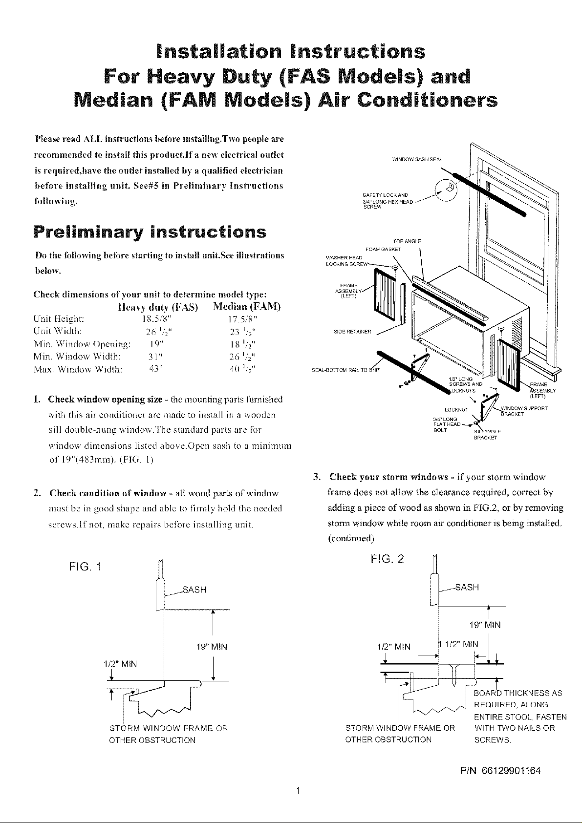
SAFETY LOCKAND
Check dimensions of ynur unit to determine model type:
Heavy duty (FAS) Median (FAM)
Unfl ileight: 18.>, 8 17.58"
Unit Width: 23 L,¢,
Min. Window Opening: 19" 18 _'¢'o
Min. Window Width: 31" 26 _ "
Max. Windov_, Widlh: 43" 40 L2"
1. Cheek windnw opening size - the mnuntiug parts f_lrnished
_ith this air conditioner are made to install in a wooden
sill double-hung window.The standard parts are for
wiudox_ dimensions listed above.Open sash to a minimum
of 19"(483mm). (FIG. 1)
2. Check condition of window - all wood parts of window
most be in good shape and able to firmly hold the needed
screws.If not, make repairs before installing unit.
FIG. 1
(LEFT)
LOOKNUT WINDOW SUPPORT
3/4,, LONG _ _RACKET
_OkAk_rHKA D "_-l_ Sl_k N G LE
.
Cheek your storm windows - if your storm window
frame does not allow the Clearance required, correct by
adding a piece of wood as shown in FIG.2, or by removing
storm window while room air conditioner is being installed,
(continued)
BRACKET
_ _SASH
19" MIN
1/2" MIN
STORM WINDOW FRAME OR
OTHER OBSTRUCTION
T
FIG. 2 _ASH
19" MIN
1/2" MIN ! 1/2" MIN
T--TH ,
BOARD THICKNESS AS
EQUIRED, ALONG
} _ ENTIRESTOOL, FASTEN
STORM WINDOW FRAME OR WITH TWO NAILS OR
OTHER OBSTRUCTION SCREWS.
P/N 66129901164
Page 2
4. CHECK FOR ANYTHING THAT COULD BLOCK
AIRFLOW- check area outside of window for things
such as shrubs, lrees, or awnings. Inside, be sure
furniture, drapes, or blinds will not stop proper air flow.
S. Check the availaMe electrical service - lmwer supply mtt_t
be the same as that shown on the unit serial nameplate.
(See Owner's Guide for serial plate location.)Power cord
is 48"long. Be sure you have an outlet near.
All models have a 3-prong service plug to provide proper
service and safe positive grouding. Do not change plug in
any way. Do not use an adapter plug. If your present wall
outlet does not match yore plug, call a qualified eleclriciml
lo make the needed change.
Avoid firehazed o1"electric
shoclcDo not useanextensioncolvlo1"an
adaptorplug.Donotremoveanyp!ongfrom
thepowercord.
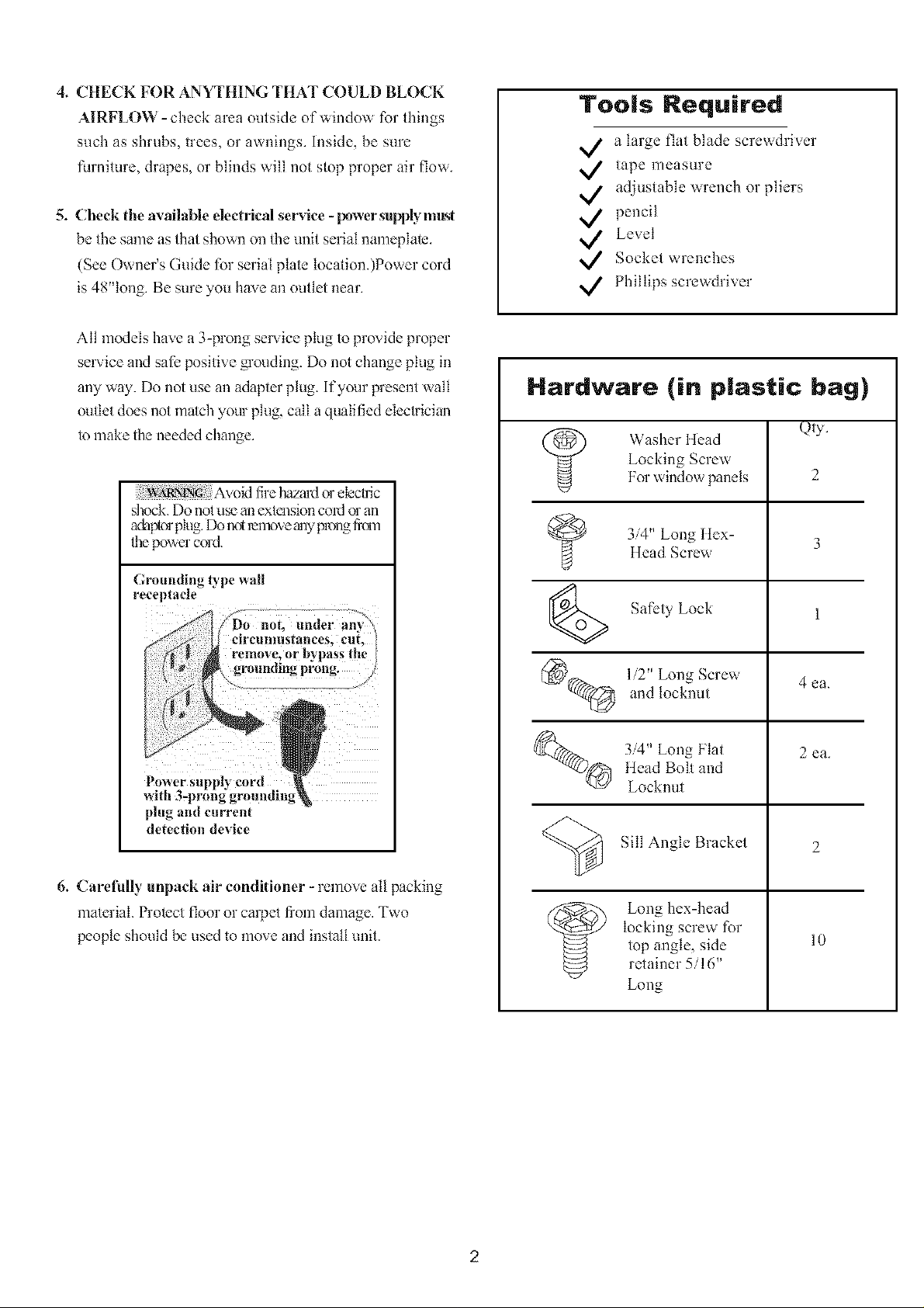
Tools Required
a large flat blade screwdriver
tape measure
adjustable wrench or pliers
pencil
Level
Socket wrenches
Phillips screwdriver
Hardware (in plastic bag)
Qly.
Locking Scre,s
Washer Head
For '_indow panels
3/4" Long ttex-Head Screv\
2
Crounding _rpe _all
receptacle
plug anti current
detection device
6. Carefully unpack air conditioner - remove all packing
material Protect floor or caq)et fi'om damage. Two
people should be used to move and install unit.
Safety Lock
(_ 1:2" Long Scre,,
_)Q 3:'4" Long Flal
_ Long hex-head
and tocknut
ttead Bolt and
Locknut
Sill Angle Bracket
locking screw for
top angle, side
retainer 5/!6"
Long
4ca.
2 ca.
2
10
Page 3
Window Mounting
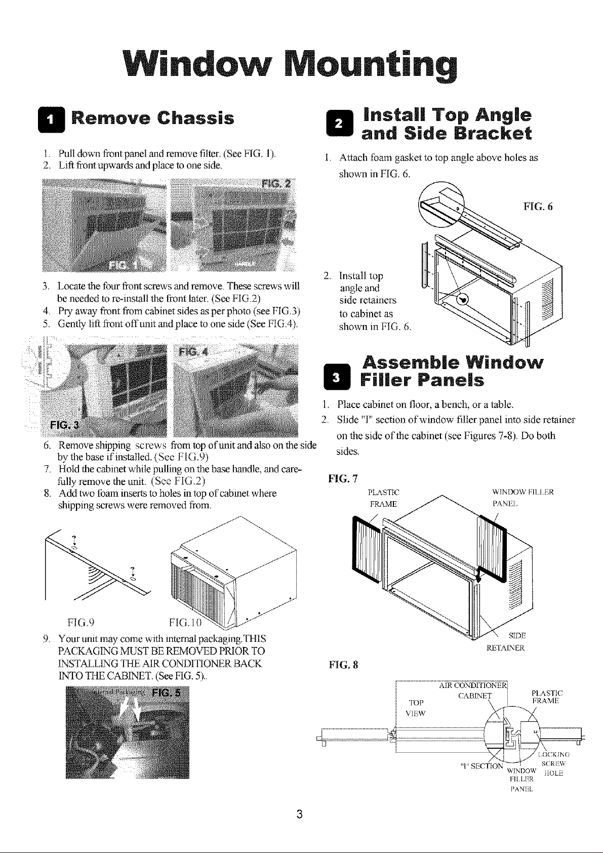
H Remove Chassis
1. Pull down front panel and remove filter. (See F[G. 1).
2. Lift front upwards and place to one side.
3. Locate the four front screws and remove. These screws will
be needed to re-install the front later. (See FIG.2)
4. Pry away fi-ont from cabinet sides as per photo (see NG.3)
5. Gently lift front offunit and place to one side (See FIG.4).
i/
6. Remove shipping screws from top of unit and also on the side
by the base if installed. (See FIG.9)
7. Hold the cabinet while pulling on the base handle, and care-
fully remove the unit. (See FIG.2)
8. Add two lbam inserts to holes in top of cabinet where
shipping screws were removed from.
_ install Top Angle
1. Attach lbam gasket to top angle above holes as
2. Install top
and Side Bracket
shown in FIG. 6.
FIG. 6
angle and
side retainers
to cabinet as
shown in FIG. 6.
Assemble Window
H FRier Panels
1. Place cabinet on floor, a bench, or a table.
2. Slide "I" section of window filler panel into side retainer
on the side of the cabinet (see Figures 7-8). Do both
sides.
FIG. 7
PLASTtC VqlN DOW FILLER
FILA_ME PANEI
FIG.9 FIG. 10
9. Your umt may come with internal packaging_TIllS
PACKAGING MUST BE REMOVED PRIOR TO
INSTAl,LING THE AIR CONDITIONF_ BACK
1NTO THE CABINET. (See FIG. 5).
SIDE
REIAINER
FIG. 8
TOP ( ABINET PLA srrlcFRAME
..........................................Xii_i)_;Sf[:igiq_
" (N
I SECTI) _,_N v,
LDO ' IIOLE
]qLLER
PAN L
3
Page 4

3. Inserl lop and bottom Iegs of window filIer panel frame
into channel in the to angle and bottom rail. Do both
sides.
4. Insert washer head locking screws (2) into holes in
top leg of filler panel frame (see Step 6). Do not tolally
tighten. Allow leg to slide fi'cely. :;crows will be
tightened after Section 6.
Place Cabinet in
Window
I. Open x_indow and mark
center of windo_ stool.
|nstaR Support
Bracket
I. Hold each support bracket flush against outside &sill,
and tight to bollom of cabinet as shown below. Mark
brackets al top level of sill, and remo_ e.
2. Place cabinet in window with bottom stool angle firmly
scated over window stool as shown. Bring window
do_l tcmpomrily behind top angle k) hold cabinet in
place.
STOOL
3. Shift cabinet left or right as needed lo line up cenler of
cabineI on center line marked on sIool.
4. Faslen cabinel to window stool wifll 2 screws into
holcs.(You may wish to pre-drilI pilot holes.)
5. Add bottom rail seal over screws to v_indow stool.
LEFI
SILL ANGLE
(_ /2" LONG S(REWS
f
FLA'I HEAl) BOL'I
2 EACH REQ'D FOR EACIq
SUPPOR'I BIL_.( KE']
2. Assemble sill angle bracket to support brackets at the
marked posilion, as shown, lland tighten, but allow
for an 3 changes later.
3. Install support brackets (with sill angle brackets
almched) to correct hole in bonom of cabinet as shown.
4. Tighten all 6 bolts securely.
t-
Bottom
Rail Seal
m
/2" {ong screws
al_d locknuts
o-,N //°
4
Page 5

Extend Window Filler
Panels
1. Carefully raise windnw to expose filler panel locking
screws. Loosen screws so filler panels slide easily.
2. Extend panels to fill windo\_ opening completely.
Tighten locldng screws on top.
3. (lose windo_ behind top angle.
install Chassis into
Cabinet and install
Front to Unit
1. Lift air conditioner and carefully slide into cabinet
leaving 6" protruding.
2. _DO not push oll controls OR finned coils.
3. Be sure chassis is firmly seated towards rear of cabinet.
4. [nstallation of fl'ont is the reverse of removal outlined
in Section 1.
Install Window Lock
and Sash Seal
1. Trim sash seal tn fit _indow width. Insert into space
between upper and lower sashes.
SEAL
2. Attach right angle safety loci( as shown.
LOCK
314" long hex-
_ead screw
Page 6

Thru-The-Wall Installation
NOTE: (onsult local building codes prior to installation,
or a qualified carpenter.
Select Wall Location
This air conditioner has a slide-out chassis, so that it can be
installed through an outside wall as specified below:
Heavy Duty (FAS) Median (FAM)
Max wall thickness 1If" 8"
IMPORTANT: Side louvers must never be blocked.
NOTE: All parts needed fur Thru-The-Wall Installation are
provided,except a wood frame, shims, and l tt wood screws 1#
1It- 1" long minimum). Select a wall surface that:
1. does not suppmt m_kjor structural loads such as the frame
construction at ends of windows, and under truss-bearing
points, etc.
2. does not have plumbing or wiring inside.
3. is near existing electrical outlets, or where another outlet
can be installed,
4. faces, and is not blocked to the area to be cooled.
5. allows unblocked airflow t'rom rear sides and end (outside)
of installed air conditioner.
Carefully measure and cut an opening with the following
dimensions depending on your model. See FIGS. land 2.
WIDTH "X" inside model width plus twice the thickness
of framing material used.
HEIGHT "Y" inside model height plus twice the thickness
of framing material used.
Heavy Duty (FAS) Median (FAM)
Inside Frame Height: l g7is" (47.9cm) 18" 145.7cm)
Inside Frame Width: 263a" (67.9cm) 237/s" (6Ih6cm)
FIG. 2
8-112"
Prepare Wall
1. Prepare wall in flame construction (including brick and
stucco veneer). Working from inside the room, find wall
stud nearest the center of area where air conditioner will
be installed (by sounding wall, or by magnetically finding
nails).
2. Cut or knock out a hole on each side of center stud.
3. Measure between inside edges of ever_ other stud as shown
in FIG. I.
FIG. t
3-318"MIN
(8.6 cm)
4. Build a wooden frame with the INSIDE dimensions of
your model listed above.(Measure twice remember...)
Frame depth should be the same as _all thickness. Fill in
the space from the opening to the studs with wood spacers,
as showu.
5. Nail framd to spacers to spacers with front flush with
dry wall.
{l
H
Page 7

NOTE: If wall thickness is 8-1/'2" o1"more, add alumhmnl
flashing o_er bottom of flame opening to assure no v_aler
can enter area between inner and outer wall.
F1G.2
I"LONG
\VOOD SCREW
Refer to Step 4 of Window Mounting for assembly of
support brackets.A wooden strip nailed lo the ou/side
wall should be used in conjunction with sill support
angle brackets.
Prepare and Instal!
Cabinet
1. Slide chassis from cabinet. Refer back to Step 1of
Window Mounting.
2. Place cabinet inlo opening with bottom rail msiing
finnly on botlom board of wooden frame.
3. Position cabinet to achieve proper slope tbr water removal.
(See FIG.t below.)
FIIG.I
3/4"PLUS
THICKNESS
5/16"
TO
3/8"
SEE PARA 5
brakcet
Wooden si-rip
5. Screw or nail cabinet wooden flame using shims if
fi'anae is oversized, to eliminale distortion. Remember
m maintain proper slope as described in Step 3.
LEVEL
4. Secure bottom rail lo wood fi'ame vxillalwo large v,ood
screx_s l"(2.5 cm)Iong using the lwo holes in lhe bol:tom
of the channel resting on fi'ame.(See FIG.2 following)
6. Inslall chassis into cannel by following all steps in
Step 8 of Window Mounting.(continued)
Page 8

OPTIONAL:Caulkingandinstallationof trimoninterior
wallmaybedone.Youcanbuywoodfromyourlocallumber
o1"hardwaresupply.Ontheoutside, caulk openings around k_p
and sides of cabinet, and all sides of wood sleeve to the opening.
NOTE: See Step 7, item 3 of Window Mounting Instructions
for bottom rail seal location.
Masonry Construction
!. Cut or build a wall opening in the masonry wail similar
to the frame construction(refer to Step 2 of Thru-the-WalI
Inslallation for a wall thickness greater lhan 8-1/2").
2. Secure cabinet in place using masonry nails, or the right
masom T anchor screws.(Another way to do Hlis is lo build
an in -between frame of 2x4 's as shown in lhe Step 2 Prepare
Wall illustmtions-but mal<c it double fi'amed on either side,
mid install belween masonry wall opening and cabincl.
Frame must be securely anchored lo masonry wail opening)
This way gives vel_ good louver clearance on eifl_erside ofcabinel.
3. install a linted lo support mason U wail above cabine_.
Existing holes in cannel cgul be used and/or additions holes
can be drilled to fasten cabinet m vmious positions.Be sure
that side louver clearalce is in accordance wilh Slop I above.
4. install exterior cabient supppon bmcl<els as shown in
Step 2 of Thru-/he-Wall Installation.Caulk or flash if
neede, to provide a welher-tight seal around top and sides
of cabinet.
5. To complele installalion, apply wood 1rimmolding
around room side projection of cabinet.
 Loading...