

Page 1
Instructions
For Heavy
Median {FAM
Please read ALL instructions be_hre installing.Two people are
recommended to install this prodaetdf a new electrical outlet
is reqaired,have the outlet installed by a qaalified electrician
be_re installing anit. See#5 in Prdiminary lnstraetions
_bllowing.
Duty {/:AS Models) and
Models) Air Conditioners
Preitiminary
Do the _bHowiog be_bre startiog to iostall aoR.See illustrations
bdow.
Check dimensions of your unit to determine model type:
Heavy duD' (FAS) Median (FAM)
Unit Height: 18.5/8" 17.5/8"
Unit Width: 26 1/. 23 1/.
Min. Window Opening: 19" 18 72"
Min. Window Width: 31" 26 1/,,
Max. Window Width: 43" 40 1/2"
SIDE RETAINER /
1°
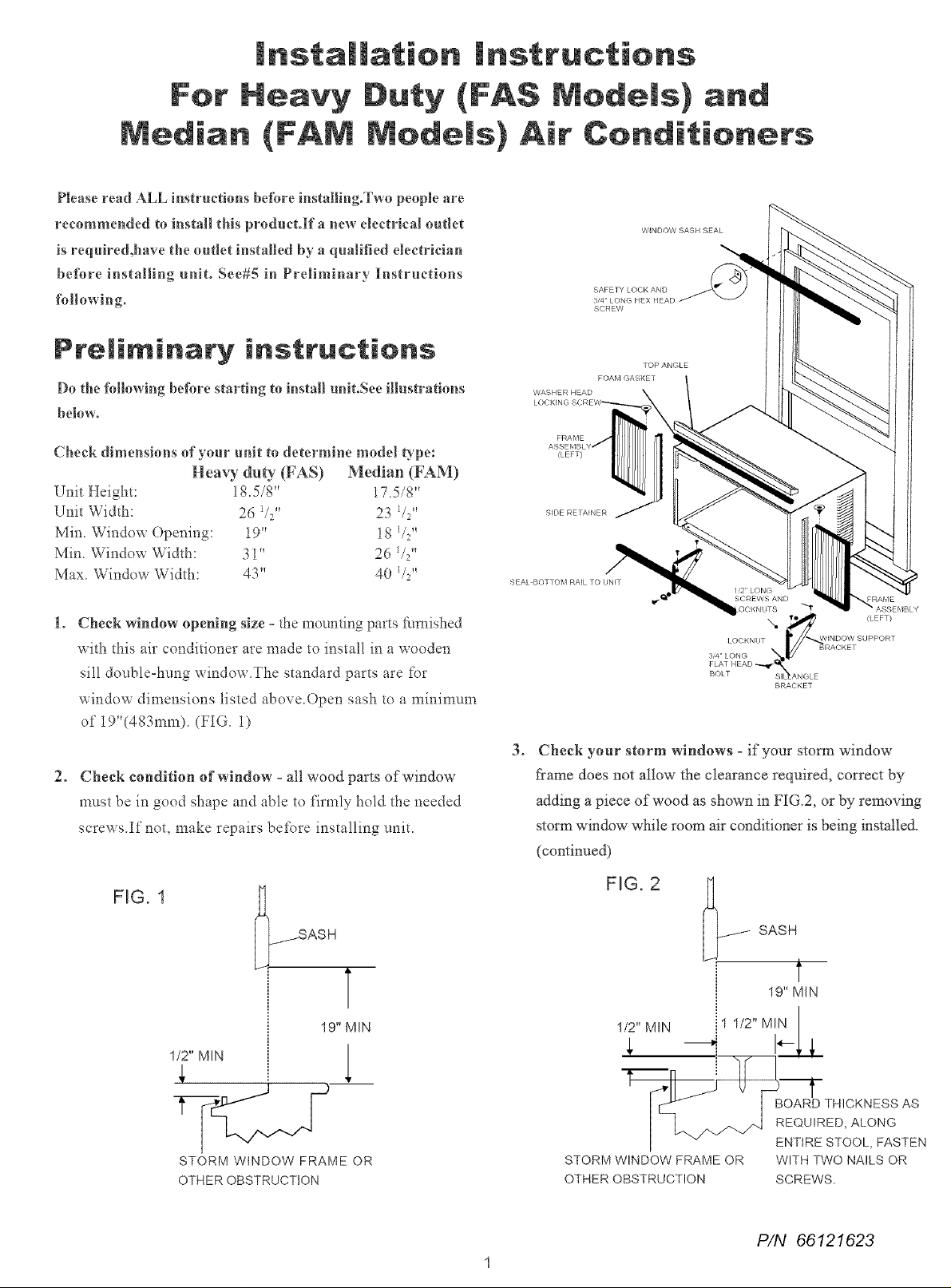
Check window opening size =the mounting parts furnished
with this air conditioner arc made to install in a wooden
sill double-hung window.The standard parts are for
window dimensions listed aboveX)pen sash to a minimum
of i9"(483mm). (FIG. i)
2. Cheek condition of window =all wood parts of window
must be in good shape and able to firmly hold the needed
sorer s.If not, make repairs before installing uniL
FIG. 1
SASH
T
19"MIN
1/2" MIN
1
BRACKET
3_
Check your storm windows =if your storm window
*?ame does not allow the clearance required, correct by
adding a piece of wood as shown in FIG.2, or by removing
storm window while room air conditioner is being installed.
(continued)
FIG. 2
SASH
t
19" MIN
1/2" MIN i 1 1/2"MIN
STORM WINDOW FRAME OR
OTHER OBSTRUCTION
I _ ENTIRESTOOL,FASTEN
STORM WINDOW FRAME OR WITH TWO NAILS OR
OTHER OBSTRUCTION SCREWS.
P/N 66121623
Page 2
4. CHECK FOR ANYTHING THAT COULD BLOCK
AIRFLOW- check area outside of window for things
such as shrubs, trees, or awnings. Inside, be sure
flu_nimre, drapes, or blinds will not stop proper air flow.
5. Check the avaiiaNe deetrkai service - power suppb_ must
be the same as that shown on the unit serial nameplate.
(See Owner's Guide fbr serial plate location. _Power cold
is 48"long. Be sure you have an outlet near.
All models have a 3-prong sel_Ace phlg to provide proper
sel_/ice and sate positive groudmg. Do not change plug m
any way. Do not use an adapter plug. If your present wall
outlet does not match your plug, call a qualified electlician
to make the needed change.
NC Avoid ISlehazad or electric
shock. Do not use m_extension cord or gm
adaptor phlg. Eb not remove _uLvprong fi_om
the power cord.
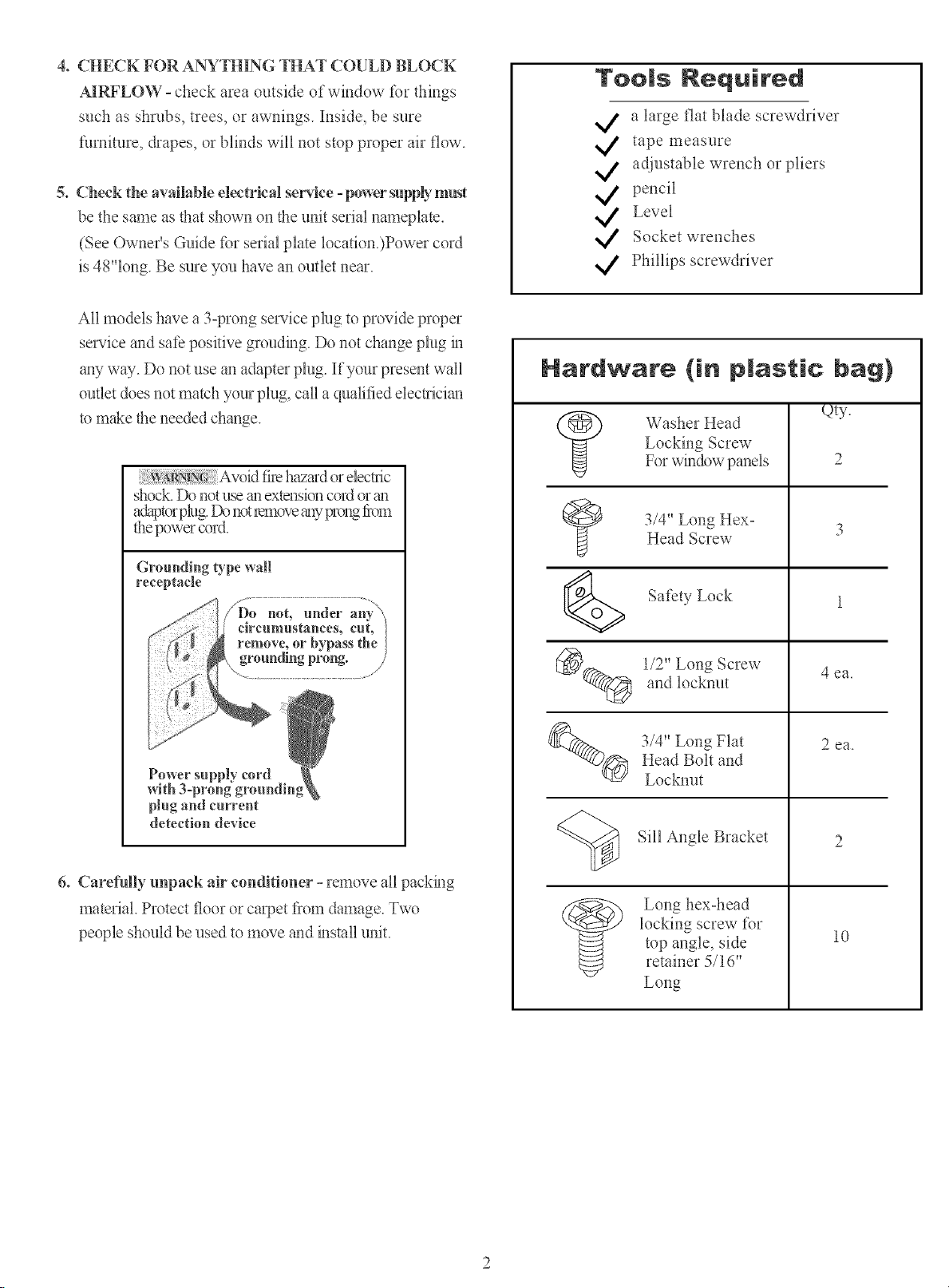
Too s Nequired
a large flat blade screwdriver
tape uleasure
adjustable wrench or pliers
pencil
Level
Socket wrenches
Phillips screwdriver
Hardware {in plastic bag)
Qty.
,_ Washer Head
Locking Screw
For window panels
3/4" Long Hex°Head Screw
2
Groundhog type wall
receptacle
./ .............................................................
circul
re o,
_, grou_
plug and current
detection device
6. Careful b, unpack air conditioner - remove all packing
material. Protect floor or carpet ti_om damage. Two
people should be used to move and install unit.
Safety Lock
@_ 1/2" Long Screw
__ 3/4" Long Flat
and locknut
Head Bolt and
Locknut
Sill Angle Bracket
locking screw %r
top angle, side
Long hex-head
retainer 5/16"
Long
4 ea.
2 ea.
10
Page 3
Remove Chassis
lnstatm Top Angl÷
and Side Bracket
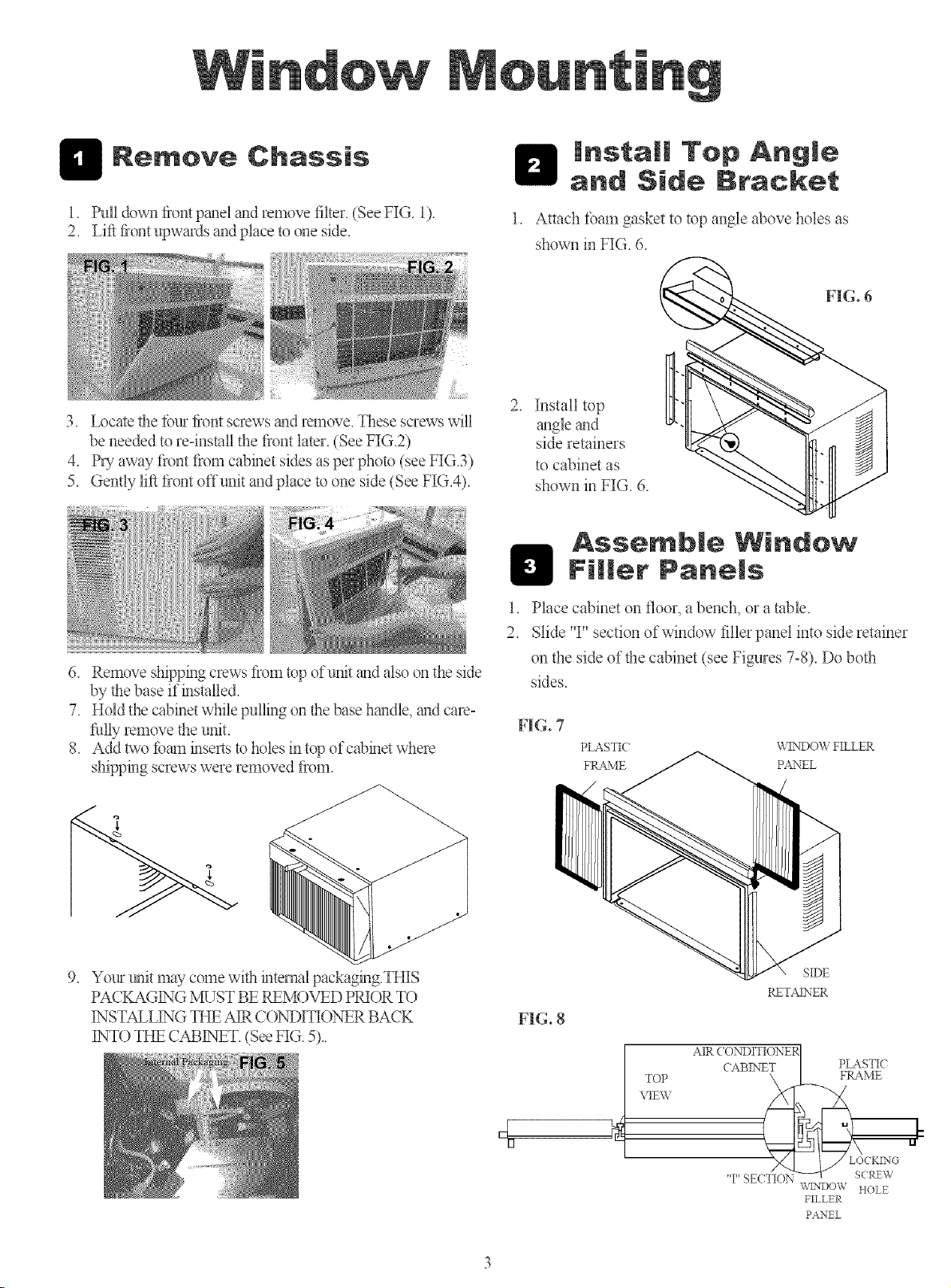
1. 1hill down ftont panel axt remove filter. (See FIG. !).
2. Lift ftont upwards and place to one side.
3. Locate file fimr flont screws _mdremove. These screws will
be needed to re=install the flont later. (See f'IG.2)
4. PU away flont flom cabinet sides as per photo (see FIG.3)
5. Gently lift flont offunit and place to one side (See FIG.4).
6. Remove shipping crews flom top ofumt gradalso on the side
by the base if installed.
7. Hold the cabinet wNle pulling on the base hgmdle, gradcare-
fillly lemove the unit.
8. Add two i[)_un inserts to holes in top of cabinet where
shipping screws were removed flom.
Attach tbam gasket to top angle above holes as
shown in FIG. 6.
2. Install top
gmgk grad
side retainers
to cabinet as
shown in FIG. 6.
Assemble Window
Fill÷r Panels
Place cabinet on floor, a bench, or a table.
2.
Slide 'T' section of window filler panel into side retainer
on the side of the cabinet (see Figures 7°8). Do both
sides.
FIG. 7
PLASTI( \r_TNDOV, FILLER
FRAME PANEL
9. Your unit may come wifil internal packaging.THIS
PACKAGING MUST BE P,EMOVED PRI()R T()
INSTALLING THE AIR C()NDITIONER BACK
INT() THE CABINET. (See HG. 5)..
d
[3
FIG. 8
RETASNER
TOP
VIEW
i AIR ( O)q)ITIONE_
CABE','ET
T' SECTION
SIDE
PLASTIC
FRAME
WENT)OW HOLE
FILLER
PANEL
Page 4

3. Insel_ top and bottom legs of window filler panel flmne
into chmmel in the to angle and bottom rail. Do both
sides.
4. Insert washer head locking screws (2) into holes in
top leg of filler panel flame (see Step 6). Do not totally
tighten. Allow leg to slide freely. Screws will be
tightened after Section 6.
Place Cabinet in
1. ()pen window and mark
center of window stool.
Rnstal! Support
1. Hold each support bracket flush against outside of sill,
and tight to bottom of cabinet as shown below. Mark
brackets at top level of sill, and remove.
MARK
w'
2. Place cabinet in window with bottom stool angle tS*mly
scated over window stool as shown. Bring window
down temporarily behind top angle to hold cabinet in
place.
3. Shift cabinet left or right as needed to line up center of
cabinet on center line marked on stool.
4. Fasten cabinet to window stool with 2 screws into
holes.(You may wish to pre=drill pilot holes.)
5. Add bottom rail seal over screws to window stool.
FLAT HEAD BOLT <_li_ _J
2 EACH REQ'D FOR EACH
SL PPORT BRA(KET
2. Asscmble sill angle bracket to support brackets at the
marked position, as shown. Hand tighten, but allow
_br any changes later.
3. Install support brackets (with sill angle brackets
attached) to correct hole in bottom of cabinet as shown.
4. Tighten all 6 bolts securely.
__i!ii}}}i_.i_i{.i_i{.i_i{.i_i{.i_{iil![!i;_!ii!ii!ii!ii!ii!ii!ii!i_;_i_(
m
t I
( --] }
v" tong screws
and locknuts
Page 5
Extend Window Filler
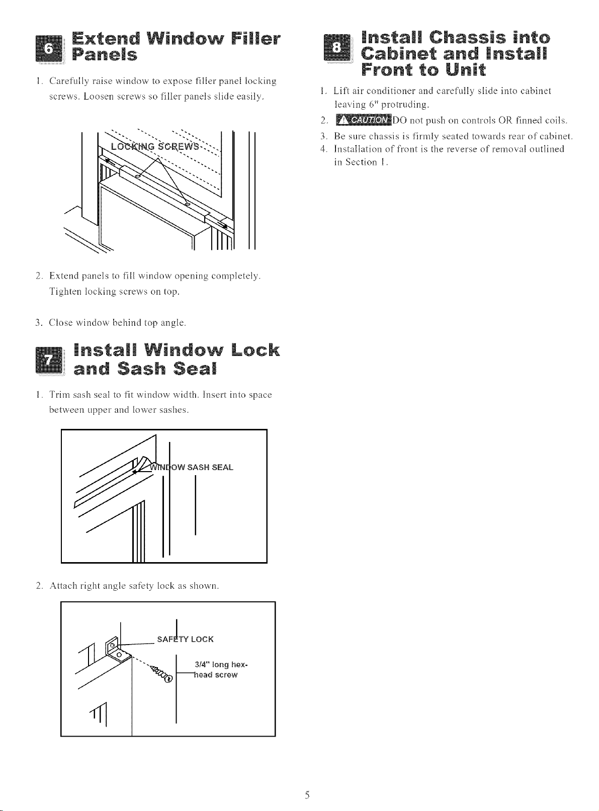
1. Carefully raise window to expose filler panel locking
screws. Loosel_ screws so filler pal_els slide easily.
2. Extend panels to fill window ope_i_g completely.
Tightel_ lockir_g screws (m top.
3. Close \_i_dow behind top al_gle.
tnstam! Chassis into
Cabinet and |nstall
Front to Unit
1, Lift air c(mditiooer al_d carefully slide ioto cabioet
leaving 6" protruding.
2, _DO _ot push oft cootrols OR firmed coils.
3. Be sure chassis is firmly seated towards rear ofcabioet.
4. h-tstallation of front is the reverse of removal outlioed
il_Sectiol_ 1.
install Window Lock
and Sash Seal
1. Trim sash seal to fit \_il_dow \_idth. Insert il_to space
between upper al_d lower sashes.
OW SASH SEAL
2. Attach right ar@e safety lock as showrt.
sA .oo,
),-'_'---.,_ I _,4,.,oo0hox.
_ _ _-_oo0_oro_
< /
Page 6
Thru-The-Wall Installation
NOTE: Consult local building codes prior to installation,
or a qualified carpenter.
H Select Wall Location
This air conditioner has a slide-out chassis, so that it can be
installed through an outside wall as specified below:
Heavy Duty (FAS) Median (FAM)
Max wall thickness 12" 10"
IMPORTANT: Side louvers must never be blocked.
NOTE: All parts needed for Thru-The-Wall Installation are
provided,except a wood *¥ame, shims, and 10 wood screws (#
10-1" long minimum). Select a wall surface that:
1. does not support major structural loads such as the lYame
construction at ends of windows, and under truss-bearing
points, etc.
2. does not have plumbing or wiring inside.
3. is near existing electrical outlets, or where another outlet
can be installed,
4. faces, and is not blocked to the area to be cooled.
5. allows unblocked airflow from rear sides and end (outside)
of installed air conditioner.
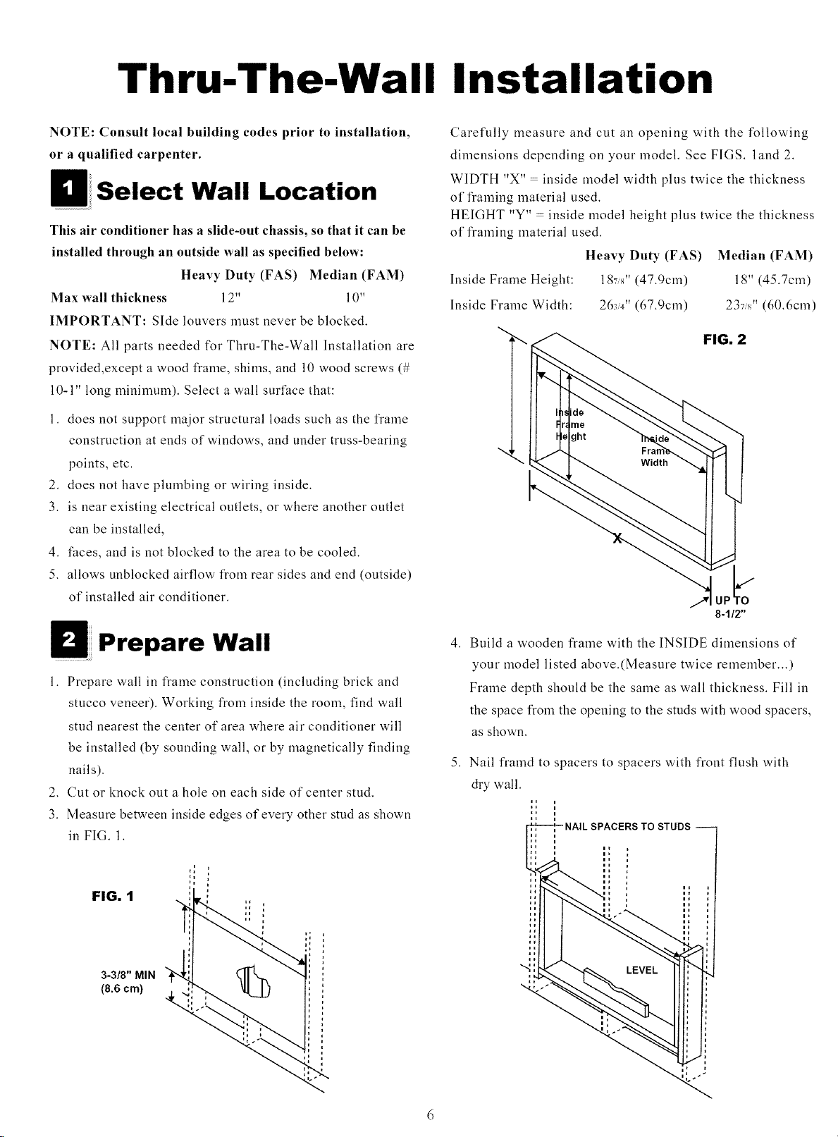
Carefully measure and cut an opening with the following
dimensions depending on your model. See FIGS. land 2.
WIDTH "X" - inside model width plus twice the thickness
of lYaming material used.
HEIGHT "Y" - inside model height plus twice the thickness
of *¥aming material used.
Heavy Duty (FAS)
Inside Frame Height: 187/d' (47.9cm)
Inside Frame Width: 263_" (67.9cm)
Median (FAM)
18" (45.7cm)
237s" (60.6cm)
FIG. 2
Prepare Wall
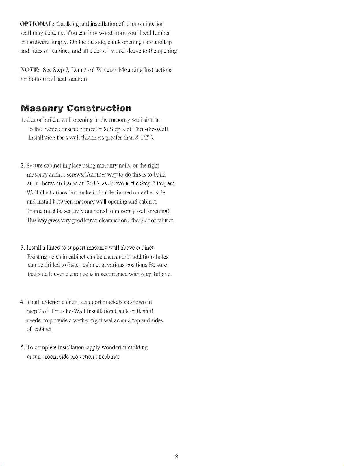
1. Prepare wall in frame construction (including brick and
stucco veneer). Working l¥om inside the room, find wall
stud nearest the center of area where air conditioner will
be installed (by sounding wall, or by magnetically finding
nails).
2. Cut or knock out a hole on each side of center stud.
3. Measure between inside edges of every other stud as shown
in FIG. 1.
FIG. 1
3-3/8" MIN
(8.6 era) ,Q
4. Build a wooden flame with the INSIDE dimensions of
your model listed above.(Measure twice remember...)
Frame depth should be the same as wall thickness. Fill in
the space l¥om the opening to the studs with wood spacers,
as shown.
5. Nail framd to spacers to spacers with front flush with
dry wall.
Page 7

NOTE: If wall thickmess is 8-1/2" or more, add alumimnn
flashing over bottom of fimne opening to assure no water
can enter area between inner and outer wall.
AL[JMINUIM FLASHING
O_ER BOTTOM OF FRAME
Prepare and lasta
Cabiaet
FIG°2
1"LONG
WOOD SCREW
Refer to Step 4 of Window Mounting _br assembly of
support bmckets.A wooden strip nailed to the outside
wall should be used in conjunction with sill support
angle brackets.
1. Slide chassis fiom cabinet. Reier back to Step 1 of
Window Mounting.
2. Place cabinet into opening with bottom rail resting
_kmly on bottom board of wooden fiame.
3. Position cabinet to achieve proper slope for water removal.
(See FIG. 1 below.)
FIG°I
3/4"PLUS
--TRIM THICKNESS
5/16"
TO
3/8"
LEVEL
SEE PARA 5
I
brakcet
Wooden strip
5. Screw or nail cabinet wooden frame using shims if
fiame is oversized, to eliminate distortion. Remember
to maintain proper slope as described in Step 3.
4. Secure bottom rail to wood flame with two large wood
screws i"(2.5 cm)long using the two holes m the bottom
of the chmmel resting on fimne.(See FIG.2 _bllowing)
6. Install chassis into cabinet by following all steps in
Step 8 of Window Mountmg.(continued)
Page 8
OPTIONAL:Cmllkingandinstallationof tfimoninterior
wallmaybedone.YoucanbuywoodIiomyourlocallumber
orhardwaresupply.Ontheoutside,caulkopeningsaroundtop
andsidesof cabinet,andallsidesof woodsleevetotheopening.
NOTE:SeeStep7,Item3of WindowMountingInstructions
lotbottomrailseallocation.
Masen Construction
1. Cut or build a wall opening in the in,f_sonFyvcall $11Y1i1,5_1
to the fiame constmction(reler to Step 2 of Thin=the=Wall
Installation lot a wall thicM3ess greater than 8=1/2").
2. Secure cabinet in place using masom-y nails, or the fight
masom 7 anchor screws.(ka_other way to do this is to Nlild
an m °between fiame of 2x4 's as shown m the Step 2 Prepare
Wall illustrations=Nit make it double flmned on either side,
and install between masom-y wall opening and cabinet.
Frame must be securely anchored to masom-y wall opening)
This way gives ve_3/good louver cle_a_mceoneither side of cabinet.
3. Install a lh_ted to support masom_y wall above cabinet.
Existing holes in cabinet can be used and/or additions holes
can be drilled to li_sten cabinet at various positions.Be sure
that side louver clearance is m accordance with Step 1above.
4. Install extefior cabient suppport brackets as shown m
Step 2 of Tknal=the=Wall Installation.Caulk or flash if
neede, to provide a wether=tight seal around top and sides
of cabinet.
5. To complete installation, apply wood trhn molding
around room side projection of cabinet.
 Loading...