

Page 1
PHOTO
FACT*
Fold
er
MODELS
CROSLEY
9-4O7,
9-4O7M-1,
TUNING
CO
NT.
VOL.
CONT.
ON-OFF
SW.
9-4O7M-2
I
o
m
S
o
and
60
PHONO
BAND
FM
cycles
FOCUS
CONT.
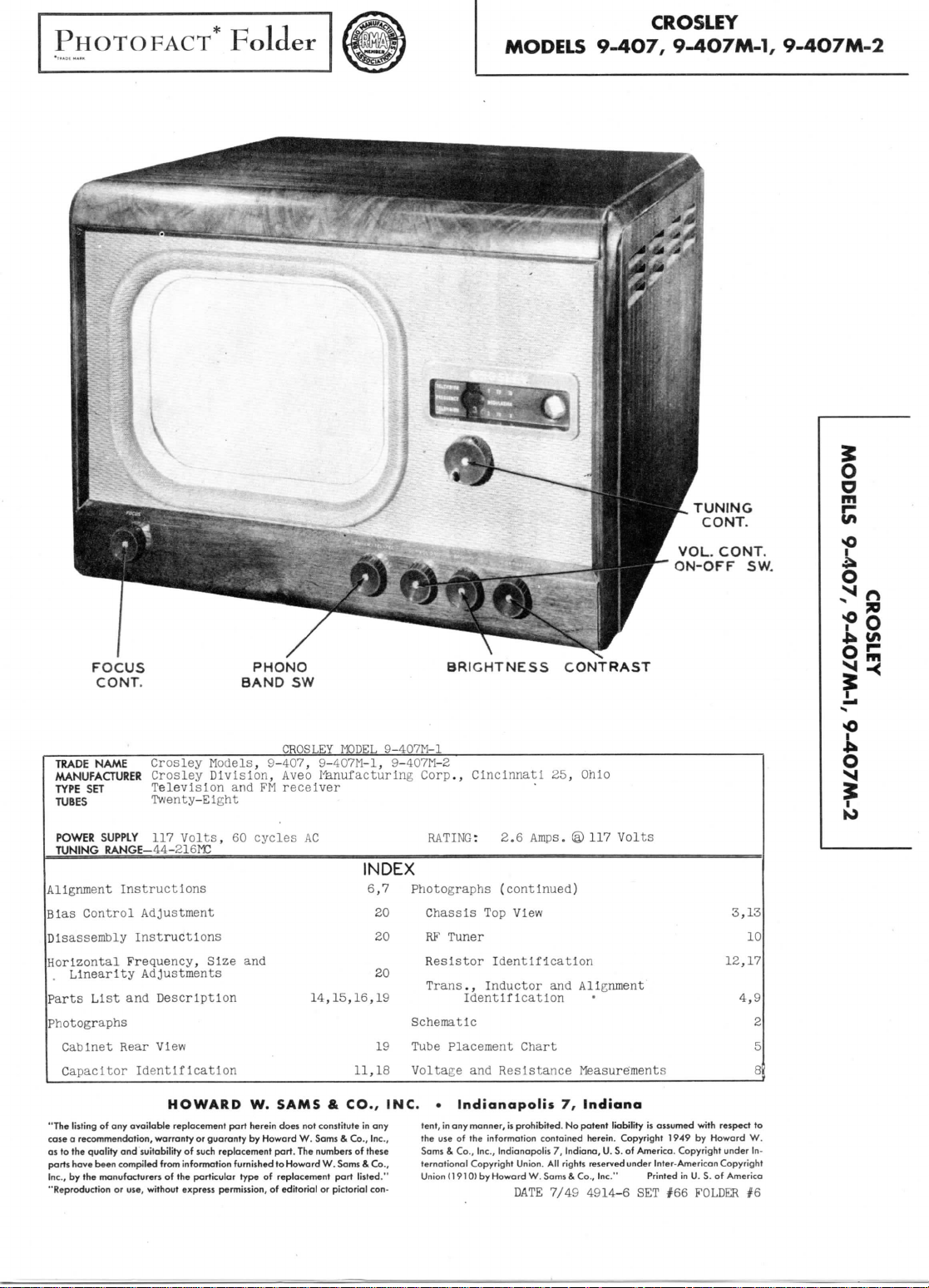
TRADE
NAME Crosley Models,
MANUFACTURER
TYPE
SET
TUBES
Twenty-Eight
POWER
TUNING
Crosley
Television
SUPPLY
117
RANGE-44-ai6MC
Volts,
Division,
Alignment Instructions
Bias Control Adjustment
Disassembly Instructions
Horizontal Frequency, Size
Linearity Adjustments
Parts
List
and
Description
and
Photographs
Cabinet
Capacitor
"The listing
case a recommendation, warranty
as
to the
parts have been compiled from information furnished
Inc.,
"Reproduction
quality
by the
Rear
View
Identification
of any
available
and
suitability
manufacturers
or
of the
use, without
HOWARD
replacement
or
of
such
particular
express
part
guaranty
replacement
permission,
W.
herein does
by
type
SW
BRIGHTNESS
CROSLEY MODEL
9-407,
9-407M-1,
Aveo
mnufacturing
receiver
AC
9-407M-1
9-407M-2
Corp., Cincinnati
RATING:
2.6
INDEX
6,7
Photographs
20
Chassis
20
RK
20
14,15,16,19
Resistor Identification
Trans.,
Schematic
19
Tube
Placement
11,18
SAMS & CO., INC. • Indianapolis
not
constitute
Howard
part.
to
Howard
of
replacement
of
editorial
W.
The
Sams & Co.,
numbers
of
W.
Sams & Co.,
part
listed."
or
pictorial con-
in any
Inc.,
these
Voltage
tent,
the
use of the
Sams & Co.,
ternational
Union
(continued)
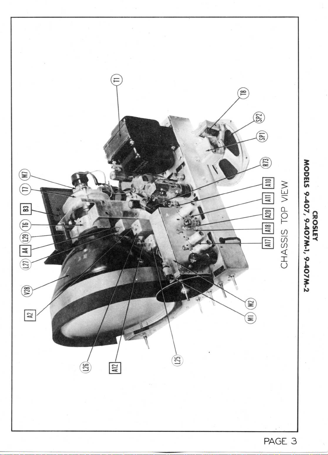
Top
View
Tuner
Inductor
Identification
and
Resistance Measurements
in any
manner,
is
prohibited.
information contained herein. Copyright
Inc., Indianapolis
Copyright Union.
(1910)
by
Howard
DATE
CONTRAST
25,
Ohio
Amps.
© 117
Volts
and
Alignment
Chart
7,
Indiana
No
patent
liability
7,
Indiana,
U.
reserved
4914-6
S. of
All
rights
W.
Sams & Co., Inc." Printed
7/49
3,13
10
12,17
4,9
is
assumed with respect
1949
by
Howard
America. Copyright under
under Inter-American Copyright
SET #66
in U. S. of
FOLDER
W.
America
#6
|5
o
N
KJ
2
5
8
to
In-
Page 2
R.r.AMP
On
gjjj
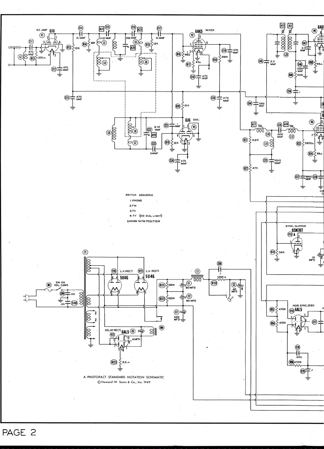
SWITCH SEQUENCE
1.
PHONO
2.FM
3.
TV
4.TV
(NO
INFM
DIAL LIGHT)
POSITION
SHOWN
PAGE
2
A
PHOTOFACT STANDARD
©Howard
W.
NOTATION
Sams & Co., Inc.
SCHEMATIC
1949
Page 3
@
1
t/MO'i
CONTRAST
-
"~"
^^^
SM^G i ^
*>
QW)^
(gjSiop-TMMF
f
1
J*
,
1
®'
@
10K
—
6800
^
MMF
-1000
"MMF
J_
'
Sflllfl
—
cL
4SB
B
+
P
<
(SK3900"
±-J
B
+
{§)
*
100 — 1
>
«
"6800
^-J<
'
1
MEG<@
~^@
! ^ <<
1
-\—
10
- MFD
)
1
^_L]00o
T
V^y
MMF
470
>wv-
>
K
J
VERT.
BUFFER
ccu-JOT
bJin/bl
xr~i.
x
/—N
(Rss)
®
AAA^i
22y>
i
.,
^
Jo)
(M)
Xl-J/i
VERT
BSK
®l
'
«OK
gj-j
Page 4
6AL7GT
Page 5
CROSLEY
SISSVHO
9-4O7M-1, 9-4O7M-2
dOl
9-407,
M3IA
MODELS
Page 6
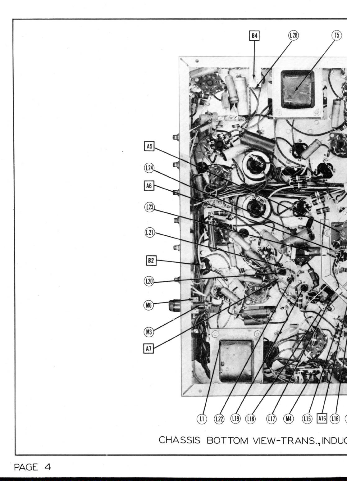
CHASSIS
BOTTOM
VIEW-TRANS.,
INDUC
PAGE
4
Page 7
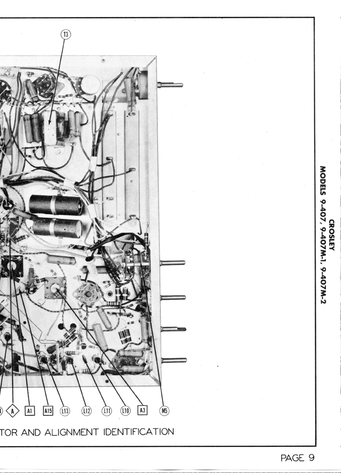
TOR
AND
ALIGNMENT IDENTIFICATION
PAGE
9
Page 8

6J6 I \^S
V2 i I V3
6AK5J
1ST
VIDEO ^ J
'•f-
MIXER \ AUDIO
'/"VI4
|6J6j(6V6GT
JOSC.
AUDIO
3RD
VIDEO
—
V3
6J6
OSC.
h
V2
6AK5
IXER
1ST
VIDEO
I.F.
VI
6J6
Rf
MwlR
/VI4
(eVSGT
OUT.
1
TUBE PLACEMENT CHART
I.F.
HOR.
A.FIC.
HOR. SYNC.
DISC.
PAGE
5
Page 9

2.
3.
5.
7.
9.
10.
11,
12.
Start
control
DUMMY
ANTENNA
.05MFD
.05MFD
.05MFD
See
Figure
DUMMY
ANTENNA
.05MFD
DUMMY
ANTENNA
.05MFD
.05MFD
.05MFD
.05MFD
.05MFD
.05MFD
.05MFD
.05MFD
Ing
the
sound
to
prevent
High
(Grid)
(V9) . Low
chassis.
High
(Grid)
(V4).
chassis.
12
High
(Or
id)
(V8).
chassis
High
(Grid)
(V6).
chassis.
High
(Grid)
(V4) . Low
chassis.
High
(Grid)
Low
side
Leave
socket.
Before
the
Place
IF
overloading.
SWEEP
GENERATOR
COUPLING
side
to pin 1
of
6AU6
side
to pin 1
of
6AG5
Low
for
the
SWEEP
GENERATOR
COUPLING
side
to
of
6A07
Low
.
SWEEP
GENERATOR
COUPLING
side
to pin 1
of
6AG5
Low
side
to
of
SAGS
it
11
side
to pin 6
of 6J6
to
Vs
out of
attempting
6K6GT
horizontal
all
test
Alignment
side
to
side
to
detector
pin
4
side
to
side
to
pin
1
side
to
(V3).
chassis,
ALIGNMENT
ALIGNMENT
equipment
with
SWEEP
GENERATOR
FREQUENCY
22MC
(IMC
probe
SWEEP
GENERATOR
FREQUENCY
Off
SWEEP
GENERATOR
FREQUENCY
24MC
(10MC
INSTRUCTIONS—
alignment,
oscillator
the
GENERATOR
FREQUENCY
21.
Sweep!
21.9MC
22.0MC
"
used
GENERATOR
FREQUENCY
GENERATOR
FREQUENCY
26.4I"C
Sweep)
26.4MC
21.9MC
1!
It
27.9MC
It
22.
26.4M3
disable
"ground"
contrast
MARKER
8MB
n
4..S
MC
in
conjunction
MARKER
4.
SMC
(400%
Mod.)
MARKER
22.9MO
21.9MC
22.
9M?
27.9MC
(Set
to
exact
sound
IF
freq.)
21.9MC
22.9MC
26.4M3
27.9MC
21.9IE
9MI
(V21)
SOUND
VIDEO
INSTRUCTIONS
READ
the
.
leads
IF
control
CHANNEL
Any
"
TRAP
CHANNEL
Any
IF AL
CHANNEL
Any
"
CAREFULLY BEFORE
high
voltage
as
close
ALIGNMENT
at
maximum.
CONNECT
Vert.
pin 6
Grid)
(V10).
to
chassis.
Vert.
Polnt<A>
side
tw
ADJUSTMENT
with
the
CONNECT
Vert . Amp . thru
detector
to pin 2 of
ture tube.
side
to
GMMENT
CONNECT
Vert.
direct
of
picture tube.
Low
side
chassis.
Vert . Amp . thru
detector
to pin 5
of
6AG5
Vert.
detector
to pin 5
of
6AL5
side
to
Vert.
direct
ture tube
(pin
2) . Low
side
to
ATTEMPTING
to
eliminate
as
possible
As the
SCOPE
Amp.
to
.(Screen
of
6AUS
Low
side
n
Amp.
to
Low
chassis.
oscilloscope.
SCOPE
probe
pic-
Low
chassis.
SCOPE
Amp.
to pin 2
to
probe
(plate)
(VS).
n
Amp.
thru
probe
(plate)
(V6).Low
chassis
n
Amp.
to
pic grid
chassis.
Al,
A3
A13,
A14
A17,
A18
ALIGNMENT
the
to
their
alignment
ADJUST
A2
A4,
AS
ADJUST
A6
ADJUST
A7,
AS,
A9
A10,
All
A12
A13,
A14
A15
A16
shock
hazard,
respective
progresses,
Adjust
for
symmetry
Adjust
symmetry
Adjust
positioned
per Fig 5 or
imum
the
to
detector
sary
Dress
the
components
versa.
will
curve
Select
bandpass.
Adjust
on
If
proper width
the
and
dips
short
L17
ment
Set
oscope
A10
curve
Adjust
"notch".
for
Reduce
control Just
for
as per Fig 9.
Adjust
into
amplitude
Adjust
into
amplitude
Retouch
per
Adjust
curve
maximum
as per
for
maximum
as
A4 so
amplitude
diagonal
peak.
Do not
plate
to
obtain
the
left g reen lead
chassis
The
determine
as
shown
curve
Repeat
for
scope
.
"necessary,
center
A9 for
curve
are
present
the
Junction
to
chassis during
of A8 and A9.
contrast
for
maximum
and All for
shape
so
21.9MC
Increase
finite
adjustment.
scope
maximum
Alb
"notch".
for
A16 so
"notch".
for
A13 and A14 for
Fig 10.
for
maximum
as per
\.
by
remove-
"hot"
leads.
reduce
the
:
REMARKS
amplitude
Fig
1 or 2.
amplitude
-per
Fig 3 or 4.
21.9MC
at
and the
dressing
minimum
of the
as per
so
marker
center
of
6.
and
line
leads unless neces-
the
and the
the
in
with
REMARKS
pattern
Adjust
AS
straightness
going
from
move
the two
proper curve.
other
chassis
of
these leads
polarity
Fig
5 and 6.
best
symmetry
steps
1 and 2.
400%
REMARKS
adjust
A7
by
changing space
control
maximum
gain
below
gain
21.9MC
Increase
finite
27.9MC
Increase
finite
gimmick
leads . Adjust
as per
Fig
In
the
curve,
of
035,
the
and the
gain.
gain
Fig
8.
marker drops
marker
and set
overlead.
and
proper
marker
marker
adjustment.
marker
marker
adjustment.
curve
gain
11.
and
Fig
contrast
and
and
is
as
for
max-
of
peak
green
against
clear
of
or
vice
of the
and
Indication
for
at
A8
7. If
C36,
and
adjust-
oscill-
Adjust
and
Into
amplitude
contrast
Adjust
curve
drops
drops
as
proper
MAX.
BANDWIDTH
FIG.
PAGE
I
6
FIG.
21.6
21.9
/
V
MAX.
BANDWIDTH
2
FIG.3
MIN.
BANDWIDTH
FIG.5
>
2.0>.
MAX.
BANDWIDTH
FIG.6
Page 10

(A . Unsolder
!B
.
'c . Remove
D . Remount
rE
Reconnect
'F
Check
'
(G).
The
DUMMY
ANTENNA
13.
Fwo
125S
carbon
res
.
„
14.
n
15
.
(A) . Leave
(B).
(C).
(D).
(E) . After
(F).
DUMMY
ANTENNA
16.
Fwo
125S
carbon
res.
n
17.
CAUTION:
All
18.
using
various types
the
blue
Remove
the RF
the
the RF
the
dial
and the No.
sound
GENERATOR
COUPLING
Across
antenna
minals with
resistor
generator
the
Solder
a 5
to the
underside
Set the
After this setting
Disconnect
other channels should
tuning control
this
dial setting).
inch
screen lead
step
channel
13
input
of the
GENERATOR
Across
minals
in
each generator
lead.
amplitude
lead only
unit mounting
bottom shield from
Tuner
the
blue lead which
dial setting
13
IF
channel must
SIGNAL
ter-
125S2
in
each
lead.
„
n
dummy
shield
inch lead
of the
on the
16 has
with a 215.75MC
the
blue lead from
oscilloscope.
SWEEP
COUPLING
antenna
ter-
with
1252
"
modulation
of
sweep equipment.
from
screws.
on the
on the
Do not
has
been completed, reconnect
the
chassis.
was
on the
shaft.
front dial
be
accurately aligned before aligning
SIGNAL
GENERATOR
FREQUENCY
71.7SMC
215.75MC
209
.75MC
203.75MC
197.75MC
191.75MC
185.
751*
179.75KC
87.75MC
81.75MC
65.75MC
59.75MC
on the
to the
screen grid
chassis.
for the
change this dial setting
been obtained
mixer tube
signal being
SWEEP
GENERATOR
FREQUENCY
69MC
(10W
Sweep)
213MC
(10MC
Sweep)
be
checked
in a
point
"
OSCILLATOR ALIGNMENT
the lug on
tuner
and
disconnected
With
are
directly centered over
CHANNEL
4
13
12
11
10
9
8
7
6
5
3
2
tuner
as
used
of the
zero reading
unsolder
and
connect them
L10
fed to the
and,
connected
MARKER
GENERATO
FREQUENCY
71.75MC
67.25MC
215.75MC
211.25KC
for
calibration with only a signal
to
point check
Llo.
replace
the
ftp
V>
chassis.
with
in
step
shaft
in the
CONNECT
VTVM
Probe
to
Common
to
"
RF
ALIGNMENT
during
the
6AK5
mixer tube
on
VTVM
with
for
the b
lue
the
blu
3
antenna (Follow step
to
;ether
CHANNEL
4
RF
13
RF
"C"
In-
"E"
In-
to
See
RF
eliminate
(See
step
in
align-
ment
structions.)
(See
step
in
Align-
ment
structions)
dummy
shield shown
1.
full clockwise position,
the
vertical centerline
the
oscillator circuits.
ADJUST
Point
A19
L7
oscillator
71.75MC
the low
lead connecting
to
the
vertical Input
lead
to L10 and
with
CONNECT
SCOPE
step
RF
Alignment
Instructions
See
step
Alignment
Instructions
-••-.»
Adjust
negative
side
Expand
reading
Check
reading
setting
being
alignment
(V2).
Run
fed
in
band alignment
adjust
the 5
Inch
ADJUST
"D" in
"F" In
the
A20,
A21,
.
A22
L3,
C14,
.
C17
generator
possibility
in Fig 13.
the top
for
zero reading. A positive
reading
will
the
correct setting.
of
or
compress
as
obtained
all
other channels
is
obtained
when
the
sound carrier signal
to
the
receiver.
lead through
(Follow
as
outlined
connect together with
the
oscilloscope.
he
runer
to
obtain this setting).
-een
lead, connect
Adjust
to
similar
of
rocking
causes
response curve amplitude.
between
exceed
Adjustment
accomplished
L3,
lar to
not
4.
ments have been necessary
nel
repeat
until
made
connected
of
give a bandpass
to
A21,&
A22
of A20
no
appreciably change
the two
30%.
L5 C14 and C17 for
Fig
exceed
SMC
on
channel
13, it
step
no
further improvement
.
to the
error
In
at
to
LI
of
14 to
sci
IS,
fed'
this
procedure.
antenna.
) and
t
window
of the
REMARKS
be
the
in
at the
In
give a zero
Fig
Is
of the
by the
15. The
6MC
will
16.
Impedance matching
of the
tuning shaft.
obtained
coil
turns
the
step above.
to see
that zero
correct dial
the
plate lead hole
step
13 to
step
16.
reading
to the
vertical
REMARKS
14. The
adjustment
correct when
back
and
forth
markers should
high
band
positioning
curve simi-
bandwidth should
or be
less than
13. If
be
necessary
Repeat
16 and 17
antenna terminals
rear
and
on
either
for
aero
is
obtain
the 5 -
of
4.5MC
the
in the
The
dip
Is
adjust-
for
chan-
to
can be
on
not
of
with
o
o
m
so
o
£k tf»
I5
s
"P
O
5
SCOPE
o
FIG.7
DETECTOR
22OJX.
IN34.
-AAA^-
PROBE
FIG.
FIG.
12
8 I
SOOMMF
FIG.I4
220
.001
*-
INPUT
FIG.9
FIG.
15
FIG.10
DUMMY
OUTS
I
~r~r«\
|o.4T005E\
SHIELD
EACH
APPROX. I INCH
OJE
wax.
SHOWING
TWO
PAGE?
CUT-
SQUARE
Page 11

9
Pin
UAP
SKffi
16.
TOP
T6.5K2
TOP CAP
MEASUREMENTS
8
Pin
7
Pin
200ffl
6
Pin
Offi
5
Pin
Offi
4
Pin
Offi
READINGS
3
Pin
RESISTANCE
.Iffi
2
Pin
tlSKB
Pin 1
T15KS2
Tube
6J6
Item
V 1V
68ffl
Offi
12Kffl
Offi
Offi
.Iffi
Offi
tlSKffi
6J6
3
V
68ffl
t!4Kffi
T6KSZ
t!4Kffi
T6Kffi
Offi
Offi
.ISd
.Iffi
68ffi
68ffl
1.2 Meg
1.2 Meg
6AQ5
6AG5
V 4V 5V6
55ffl
T330Kffi
T48KS2
.Iffl
Offi
55ffi
Meg.
1
6AK5
2
T7KS2
lOKa
lOOffi
Offl
ess
T6K2
T50KS2
Offi
T38Kffl
T6Kffi
Offi
.Iffi
100S2
.7ffi
6AG5
tl.SKffi
Offi
4.7Kffl
.Iffi
Offi
4.7Kffi
.IS
Offi
Offi
.12
352
OS!
150K2
Offl
260KS2
6AL5
6AC7
6AU6
7
8
V
V9
V
S.SKffl
lOOKffl
682
Offl
T12Kffl
Offi
Offl
Tl.SKffi
200Kffi
S.SKffi
.Iffi
.Iffi
1.5 Meg
TbOOffi
Offl
Offi
.Iffi
lOOKffl
OS!
Offl
56K2
S.SKffl
6AL5
6AU6
6AL7GT
1
1
10
V
V
1-V12
T100KS
Offi
Offi
Offi
Meg.
Tl
55ffl
Offl
lOOKffl
t2Kffi
SSOKffi
T2Kffi
Offi
as
.12
Offi
Offi
6SJ7
6V6GT
13V MV 15
V
.Iffl
.Iffl
TllKffi
Offi
.IS
.Iffl
Offi
Offi
950K2
T21Kffi
Offl
TKffi
2.2Kffi
820ffl
Inf.
T700K2
T35Kffl
T6Kffl
Offl
470Kffi
Meg
llet
T2.5
.Iffi
1.2 Meg
2.2
Offi
820ffi
Offi
2.2Kffi
T470K2
T6K2
20ffi
220KS
1.2 Meg
Offi
Offi
T14KS
Offi
Meg
02
1.1
600KS2
39K8
6SN7GT
6SJ7
16V 17
V
2.2 Meg
470K2
6SN7GT
6SN7GT
6AL5
V18
Y.19
SKffi
t22Kffl
T12.
21ffl
.Iffi
.Iffi
.Iffi
TSOOffi
T65ffl
27Kffi
90S
T90ffl
lOffl
1.5 Meg
TSOffl
4.7Kffi
470Kffi
tlOKffi
T90S2
570KS2
SKffi
s
6.
6.5K2
50S2
S.SKffi'
*
*
#
*
Inf.
Inf.
70ffi
70ffl
SKffi
55ffi
Inf.
!il'12
.Iffi
11
752
752
eoKffi
PIN
10
t6.5Kffl
Offl
160ffi
22KS2
Offi
Offl
T20KS
Offi
OS
Offi
Offi
85KS2
6AC7
6K6GT
6BG6G
5V4G
V20
V21
V22
V23
Inf.
2.2ffl
*
*
jf
1B3GT
V24
Inf.
190K2
PIN
volt-
to the
for
502
6.5KS
6.5KS2
Inf.
5K2
302
6AL5
5U4G
5U4G
V25
V26
V27
V27.
650K2
Offi
measure.
12JP4
V28
* Do not
volts
117
at
pin 8 of
position.
from
maintained
in FM
voltage
Taken
Measured
T
*
readings.
age
Line
4.
t
both minimum
given.
according
minimum,
ore
at
vary
set
controls,
may
service
controls
readings
of the
maximum readings
setting
and
Where
Front panels
5.
6.
RESISTANCE
AND
VOLTAGE
1,000
20,000
9
Pin
8
Pin
7
8VDC
Pin
.
.1VDC
OVOVOV
1
6
Pin
60VDC
OV
5
Pin
OV
220VDC
4
Pin
6.3VAC
OV
READINGS
VAC
3
3
Pin
VOLTAGE
6.
OV
2
Pin
.1VDC
125VDC
1
Pin
-.8VDC
125VDC
187VDC
5-7.4VDC
300VDC
300VDC
130VDC
OV
OV
OV
OV
3V AC
6.
6.3VAC
6.3VAC
0V
0V
0V
-5V
-5V
80VDC
180VDG
.2VDC
,8VDC
-.1VDC
1.2VDC
OV
140VDC
OV
170VDC
150VDC
42VDC
-2.1VDC
140VDC
OV
295VDC
295VDC
"
OV
OV
-2.1VDC
6.3VAC
6.3VAC
6.3VAC
6.3VAC
OV
OV
OV
1.2VDC
-2.5VDC
6.3VAC
0V
0V
.5VDC
0V
-.1VDC
-.2VDC
0V
195VDC
OV
6.3VAC
3.1VDC
-.3VDC
OV
OV
OV
OV
OV
-7.4VDC
45VDC
OV
OV
OV
-7.4VDC
6VDC
.
6.3VAC
OV
-
250VDC
OV
295VDC
OV
235VDC
AC
3V
-.3VDC
6.
6.3VAO
6.3VAC
0V
QV
3.1VDC
0V
6.3VAC
265VDC
OV
OV
OV
50VDC
-35VDC
OV
4VDC
-.4VDC
6.3VAC
S.3VAC
OV
-.7VDC
6VDC
11VDC
18VDCOV100VDC
43VDC
OV
-.6VDC
OV
ov
0V
.2VDC
150VDC
300VDC
OV
6.3VAC
OV
18VDC
OV
11VDC
OV
-1.5VDC
105VDC
300VDC
230VDC
0V
1.2VDC
-70VDC
-80VDC
TOP CAP
.1VDC
OV
250VDC
480VDC
6.3VAC
6.3VAC
6.3VAC
360VDC
290VDC
400VDC
400VDC
-35VDC
OV
-13VDC
400VDC
6VDC
.
-
225VDC
-13VDC
400VDC
205VDC
OV
-1.1VDC
290VDC
OV
OV
OV
480VDC
0V
0V
0V
82VDC
430VDC
430VDC
-11VDC
OV
112VAC
OV
400VAC
400VAC
12
50VDC
8.5VDC
OV
6.3VAC
PIN
11
6.3VAC
.2VAC
MEASURE
-11VDC
* DO NOT
50VDC
PIN
85VDC
400VAC
400VAC
10
OV
OV
PIN
300VDC
430VDC
OV
430VDC
0V
0V
0V
position.
FM
measure.
Tube
6J6
Item
V 1
6AG5
6AG5
SAGS
SAKS
6J6
2
V
V 4V 5V 6
V3
6AL5
V7
SAC7
V 8V9
6AU6
6AU6
6AL7GT
6AL5
V 1 1
V 10
4-V12
6SN7GT
6SJ7
6V6GT
V 13
V14
V 15
6SN7GT
6AL5
6AC7
6SJ7
6SN7GT
V18
V 16
V 17
6K6GT
6BG6G
V 1 9
V20
V21
V22
6AL5
1B3GT
5V4G
V23
5U4G
V25
V26
V24
V27
In
12JP4
5U4G
Taken
Do not
V28
#
*
at
af
are
measured
Voltage
AC
measurements
volt;
per
Voltage
ohms
DC
1.
VTVM
with
Taken
§
com-
pin to
clockwise direc a
in
from socket
otherwise stated.
socket.
ore
counted
of
unless
are
values
bottom
negative
on
numbers
ohms.
mon
tion
Measured
2. Pin
3.
5
o
m
oo
Page 12

RF
TUNER-LEFT
SIDE
PAGE
10
INDUCTUNER-TOP
VIEW
Page 13

m
oo
0
>
co
co
CO
DD
O
i
o
Page 14

DACITOR
IDENTIFICATION
PAGE
I
Page 15

CHASSIS
BOTTOM VIEW-
PAGE
12
Page 16

ESISTOR
IDENTIFICATION
PAGE
17
Page 17

BIAS
CONTROL
siaaow
VIEW
(V1J
@)
V13)(V9)@
'/Ofr-6
A31SOUD
'i-wzofr-6
CHASSIS-TOP
c-w/ofr-6
o
m
I
o3
!
Page 18

ITEM
VI
V2
V3
V4
V5
V6
V7
V8
V9
V10
Vll
V12
V13
V14
VIS
V16
•
V17
V18
V19
V20
V21
V22
V23
VS4
V25
V28A
ITEM
No.
Cl
02
C3A
C4A
C5A
06
07
08
C9
Oil
012
013
014
C16
017
018
C19
020
021
C22
C23
C24
025
C26
C28
C29
C30
C31
C32
C33
034
035
038
039
040
C41
C42
043
C44
No.
V26
V27
B
B
B
C
D
B
c
USE
IF
Amp
.
lixer
Oscillator
1st
Video
2nd
Video
3rd
Virtpn
fide
Amp.
Sound
ig
no.
Ai
Vudlo
Output
Dlsch
.
Clip
.
. Osc
a.
.
Amp
AFC
er
R
ect.
Time
LV
R
ect.
LV
Rect.
ure
Plot
Plct
ure
Picture
RATING
350
350
475
400
450
450
350
350
300
300
150
25
25
4
500
200
RRRt
Ind
Clip
Buffer-
Sync
Osc.
Output
Delay
Ti
Ti
Tube
VOLT
Video
1st
Limiter
Discriminator
Tunl
AF
Sync
Hor.
Sync
Vert
Vert
Disc
Vert
Hor.
Hor.
Hor.
Hor.
Damp
HV
CAP.
80
80
40
40
30
10
10
10
10
10
4
500
100
1.52
©
60%
470
470
470
2-12
15
470
470
470
1
2-12
5
470
1000
1000
6800
6800
2
1000
6800
6800
20
10
1000
6800
6800
1.6
1000
47
.05
.5
270
IF
IF
IF
IF
icatoi
per-
.
per
&
Disc
Rect
be
ibe
Capacity
and
Paper
CROSLEY
PART
No.
W-160039
W-160039
B-160549
W-160074
W-160076
W-
160036
W-160071
W-160073
W-160070
W-160633W-160082
W-160082
W-160080
W-160247
W-160247
W-160080
W-160082
W-160082
W-160633-
20
W-137398-2
W-160247
W-160084
W-160633-
W-160034
W-160034
W-160067
39001-87
W-160067
AW-160518
W-160034
W-160067
W-160067
W-160037
W-160083
W-160034
W-160067
W-160067
AW-160402
W-160034
W-160081
39001-17
39001-23
W-160079
CROSLEY
PART
6J6
6AK5
6J6
6AG5
6AG5
6AG5
6AL5
6AC7
6AU6
6AU6
6AL5
7GT
6AL
7
6SJ
6V6GT
6SN
7GT
6SJ
7
6SN
7GT
6SN7GT
6AL
5
6AC
7
6K6
GT
6BG6G
5V4
G
GT
IBS
6AL5
5U4
G
5U4G
12J
P4
P4
12K
12LP4
values
Capacitors,
AF16J
AF16J
AFH8K8I
AF2222JT
AF2222J
PRS
PRS25/500
PRS25/100
PRS4/2000
1468-0005
20
1468-0005
1468-0005
1468-0005
1468-0805
1468-0005
1468-000001
1468-000005
1468-0005
20
1468-001
1468-001
1467-008
P488-25
1467-008
1468-001
1467-008
1469-00001
1468-001
1467-008
1467-008
1468-001
1469-00005
P488-05
484-5
1468-00025
TUBES
REPLACEMENT
No.
given
AEROVOX
PART
No.
'
150/4
(SYLVANIA
DATA
STANDARD
REPLACEMENT
6J6
6AK5
6J6
6AG5
6AG5
6AG5
6AL5
6AC7
6AU6
6AU6
6AL5
6AL7GT
6SJ7
6V6GT
6SN7GT
6SJ7
6SN7GT
6SN7GT
6AL5
6AC7
6K6GT
:6BG6G
5V4G
1B3GT
6AL5
5U4G
5U4G
12JP4
12KP4
12LP4
CAPACITORS
in the
rating
and in
mmfd.
REPLACEMENT
CORNELL-
DUBILIER
PART
UP8045
UP8045
UP9BJ
UP1111
UP1111
BR415
BRH255
BRH251A
BRH620
5W5T5
5W5T5
5W5T5
5W5T5
5W5T5
5W5V5
5W5T5
1W5D1
1W5D1
1D3D7
GT2P25
1D3D7
1W5D1
1D3D7
1D3D7
5R5Q2
5R5Q1
1W5D1
1D3D7
1D3D7
1W5D1
5R5Q5
GT4S5
GT4P5
5W5T25
No.
965
45t
45
DATA
GP2K-500
GP2K-500
GP2K-500
GP1K-15
TS2A-N500-
2—12
TS2A-N500-
2-12
GP1K-15
GP2K-500
GP2K-500
GP2K-500
TS2A-NSOO-
NPOK-5
GP2K-500
GP2L-001
GP2L-001
GP2-335-
GP2-335-
GP3L-001
GP2-335GP2-33SNPOK-20
NPOK-10
GP3L-001
GP3-335-
GP3-335-
GP3L-001
NPOM-50
GP2K-25Q
or
BASE
TYPE
7BF
7BD
7BF
7BD
7BD
7BD
6BT
8N
7BK
7BK
6BT
3CH
8N
7AC
8BD
8N
8BD
8BD
6BT
8N
78
5BT
5L
30
6BT
5T
5T
12D
12D
12D
column
for
ERIE
PART
No.
2-12
0075
0075
0075
0075
0075
0075
Mica
Equivalent)
Used
in
model
Used
in
model
Used
in
model
are in
mfd.
for
and
Ceramic
SOLAR
SPRAGUE
PART
No.
PART
MO.5-35
MO.5-35
MO.5-35
MO.5-35
MO.5-35
MO.5-55
MO.5-35
MW.5-21
MW.5-21
MW.3-27
ST-2-25
MW.3-27
MW.5-21
MW.3-27
MW.3-27
MOS.5-42
MOS.5-41
MW.5-21
MW.3-27
MW.3-27
MW.5-21
MOS.5-45
ST-4-05
ST-4-5
MO.5-325
NOTES
9-407
9-407M-2
9-407M-1
Electrolytic
Capacitors.
AND
No.
INSTALLATION
rVL-64t
Filter
FVL-64t
Filter
TVL-20 - Filter
A
Filter
TVL-69 • Vert.
*
rVL-34 « V.
JT-41
PVA-10
rvA-8
CVL-43
LFM-35
1FM-35
IFM-35
MS-415
MS-415
IFM-35
IFM-35
LFM-35
B-55
IFM-35
LFM-21
.FM-21
.FM-27
fC-2
1FM-27
1FM-21
.FM-27
IFM-27
18-42
1S-41
.FM-21
IFM-27
IFM-27
1FM-21
TM-15
TC-5
1FM-325
Output
Q
Low
*
Sync.
3rd V. IF
Filter
Bias
Hor.
Vert.
RF
Coupling
RF
Fll.
RF
Coupling
Fixed
Fixed
RF
Coupling
Mixer
Mixer
RF
Bypass
Osc.
fixed
Osc.
Osc. Fil.
Mixer
IF
Coupling
Bias
1st V. IF
IF
Coupling
IF
Coupling
Bias
Ind
V. IF
'ixed
IF
Coupling
3rd IF
3rd IF
IF
Coupling
Diode
Ixed
Video
DO
Res.
Amp.
Filter
Cent.
Cent.
Bypass
Padder
Coupling
Grid
Filter
Filter
Trimmer
Filter
Trimmer
Coupling
NOTES
Osc. Plate Dec.
Decoupling
Screen
Filter
Plate Dec.
Decoupling.
Cont.
Cont.
Bypass
Bypass
Bypass
Bypass
Bypass
Bypass
Pass
Clip
Padder
Fil.
Screen
Trimmer
Cap.
Bypass
Plate
Decoup.
Screen
Byp.
*
Screen
Byp.
Cath.
Bypass
Screen
Bypass
Diode
Filter
ITEM
No.
C45
046
C47
C48
049
C50
C51
052
053
Q54
055
C56
057
C58
C59
060
C61
062
C63
C64
C65
C66
067
068
069
C70
071
072
073
074
075
C76
C77
C78
079
C80
081
C82
083
C84
CSS
086
087
C88
C89
C90
091
C92
093
094
C9S
096
C97
C98
099
C100
ITEM
. R7
R10A
R11A
ITEM
No.
R12
R13
R14
R15
R16
R17
R18
R19
R20
R21
R22
R23
R24
R25
R£6
No.
Rl
R2A
R3A
R4A
R5
R6
R8A
R9A
RATING
CAP.
2.S
1000
2.5
4700
1000
.1
47
1000
1000
47
47
1000
.01
.01
.02
.1
.1
6800
.05
1000
.002
.005
.01
.05
.1
.01
.005
.01
.01
.1
.1
47
.01'
.005
.1
LOOOO
.005
.05
.005
.05
330
.01
680
1000
.1
1000
.05
.035
.05
220
500
.01
.1
.1
.05
.05
t
Parallel
RESIST-
ANCE
lOOOffi
500K2
Shaft
B
Switch
C
100K2
Shaft
B
25KS2
Shaft
B
252
252
15002
500K2
B
2
Meg.
Shaft
B
20KB
Shaft
B
500K2
Shaft
B
RESISTANCE
2002
10K2
12K2
12K2
I
Meg.
47S2
330K2
12K2
10K2
82002
47K2
56002
688
68002
22K2
VOLT
500
200
400
400
400
300
400
400
600
600
400
200
200
600
600
400
400
400
400
400
600
200
300
600
200
600
400
500
400
500
500
300
400
1000
1000
1500
10000
600
200
400
600
600
Not
RATING
.
used
WATTS
RATING
PARTS
CROSLEY
PART
No.
W-160078
W-160034
W-160068
W-160634-
W-160034
39001-19
W-160109
W-160034
W-160034
W-160109
W-160109
W-160034
39001-13
39001-13
39001-80
39001-19
39001-19
W-160067
39001-17
W-160034
W-160643-3
39001-11
39001-13
39001-17
39001-19
39001-13
39001-11
39001-13
160643-4
160643-5
39001-19
W-160035
W-160643-4
39001-11
39001-19
W-
160635-
39001-11
39001-17
39001-11
39001-17
W-160632-
26
39*01-13
W-160634-3
W-160634-5
39001-19
W-160034
39001-17
W-160643-1
W-160643-2
W-160111
B-137477-1
39001-13
39001-19
39001-19
39001-17
39001-17
In
all
section
CROSLEY
PART
•25
W-160091-2
W-160031
4
W-160092-2
4
W-160032
4
2
W-
160095-1
4
W-160089
2
W-160087
W-160094-2
4
W-160094-3
4
Not
Req.
W-160094-1
4
Not
Req.
W-160088
4
WATTS
39375-32
4
2
39374-213
39374-38
4
39374-38
4
39374-61
4
39374-9
•i
^
39374-55
J|
39374-38
2
39374-213
39375-71
4
39374-45
4
39375-67
4
39374-11
4
39375-69
4
2
39374-217
AEROVOX
PART
1468-001
1467-005
14
1468-001
P288-1
1468-00005
1468-001
1468-001
1468-00005
1468-00005
1468-001
P488-01
P488-01
P488-02
P288-1
P488-1
1467-008
P488-05
1468-001
P688-002
P688-005
P488-01
P288-05
P288-1
P688-01
P688-005
P488-01
P488-01
P488-1
P488-1
1468-00005
P488-01
P688-005
P288-1
1467-01
P688-005
P288-05
P688-005
P488-05
P488-01
1479-0007
1468-001
P288-1
1468-001
P488-05
P1088-033
P1088-05
P688-01
P288-1
P488-1
P688-05
P688-05
models,
to
obtain
REPLACEMENT
No.
REPLACEMENT
CROSLEY
PART
No.
LIST
CAPACITOR
REPLACEMEI-
CORNELL-
No.
PART
'
GT6S1
GT2P1
GT4P1
desired
IRC
PART
No.
319-133X
Not
Req.
76-1
CJ11-12S
Not
Req.
Ql
1-120
Not
Req.
W-25
Qll-133
S<3
Qll-139
SQ
Qll-119
S3
«11-133
S*
DATA
PART
BTS-47K
AN
DUBILIER
No.
1W5D1
1D5D5
1W5D1
GT2P1
5W5Q5
1W5D1
1W5D1
5W5Q5
5W5Q.5
1W5D1
GT4S1
GT4S1
GT4S2
GT3P1
GT4P1
1D3D7
GT4S5
1W5D1
GT6D2
GT6D5
GT4S1
GT2S5
GT2P1
GT6S1
GT6D5
GT4S1
GT4S1
GT4P1
GT4P1
5W5Q5
GT4S1
GT6D5
GT3P1
1D3S1
GT6D5
GT2S5
GT6D5
GT4S5
GT4S1
2R5T7
1W5D1
GT2P1
1W5D1
GT4S5
GT16S5
GT6S5GT6S5
cap=
cor
DA
TA
OAR<
PW25-:
AT-82
RS-2
SW-A
AM-49-
KS-2
AM-40-
RS-2
43-25
10-25
43-151
M-58-!
Not
M-83-!
Not
M-36-:
Not
M-58-i
Not Rl
RESI
IRC
No.
•
PAR1
R.
Ri
Hi
PAGE
14
Page 19

31
9-407
il
9-407M-2
31
9-407M-1
Electrolytic
Capacitors.
IDENTIFICATION
IAGUE
!TNo.
,-641
,-64t
-
,-20
D
»
3rd
"liter
41
,-10
Bias
Hor. Cent. Cont. Bypass
i-fl
Vert. Gent. Cont.
,-43
1-15
Vert. Output
RF
1-35
1-35
1-35
RF
RF
-415
Fixed
Fixed
-415
RF
1-35
Mixer
Mixer
1-35
1-35
RF
Osc.
Osc.
-55
1-35
Osc.
1-21
Mixer
1-31
IF
1-27
Bias
-2
1-27
1st
IF
1-21
IF
1-27
Bias Filter
1-27
2nd V. IF
-42
-41
1-21
IF
1-27
3rd IF
1-27
3rd
IF
1-21
Diode
-45
•15
Video
•5
DC
AND
INSTALLATION NOTES
liter
liter
Filter
Filter
Vert.
Osc.
Output
Decoupling
V.
Amp.
Screen Bypass
Low
Pass
V. IF
Filter
Clip
Decoupling,
Sync.
Filter
Coupling
Fil.
Bypass
Bypass
Coupling
Eadder
Padder
Coupling
Fil.
Screen Bypass
Bypass
Coupling
ixed
Trimmer
Grid
Cap.
Fil.
Bypass
Plate Decoup.
Coupling
Filter
V. IF
Screen
Coupling
Coupling
Screen
ixed
Trimmer
Coupling
Oath. Bypass
IF
Screen Bypass
Coupling
Filter
Ixed
Trimmer
Coupling
Res.
Diode
CODES
Plate
Plate
Oath.
Bypass
«
Filter
Dec.
Dec.
Bypas
Byp.
Byp.
Byp.
ITEM
No.
045
C46
C47
C48
C49
C50
C51
C52
CSS
Q54
055
C56
C57
058
059
060
C61
C62
C63
C64
065
066
C67
068
069
C70
C71
072
073
C74
C75
C76
077
078
C79
C80
081
C82
083
084
C85
086
087
088
089
C90
C91
092
093
094
C95
096
C97
098
099
.0100.
ITEM
. R7
R10A
R11A
ITEM
No.
R12
R13
R14
R15
R16
R17
R18
R19
R20
R21
R22
R23
R24
R25
R26
No.
Rl
R2A
R3A
R4A
R5
R6
R8A
R9A
2.5
1000
2.5
1000
.1
47
1000
1000
47
47
1000
.01
.01
.02
.1
.1
6800
.05
1000
.002
.005
.01
.05
.1
.01
.005
.01
.01
.1
.1
47
.01'
.005
.1
LOOOO
.005
.05
.005
.05
330
.01
680
1000
.1
1000
.05
.035
.05
320
500
.01
.1
.1
.05
.05
»
Not
T
Parallel
RESIST-
ANCE
10002
500KS2
B
Shaft
Switch
C
100K2
B
Shaft
35K2
B
Shaft
352
252
1500S
500K2
B
2
Meg.
B
Shaft
20K2
Shaft
B
500K2
Shaft
B
RESISTANCE
2ooa
10K2
12KS2
12K2
1
Meg.
472
330K2
12K2
10KS2
82002
47K2
56002
682
68002
22K2
!00
400
:00
400
400
600
600
400
200
200
600
600
400
400
400
400
400
600
200
300
600
200
600
400
500
400
500
500
ZOO
400
1000
1000
1500
10000
600
200
400
600
600
used
RATING
RATING
.
PARTS LIST
CROSLEY
PART
No.
W-160078
W-160034
W-160068
W-160634-
W-160034
39001-19
W-160109
W-160034
W-160034
W-160109
W-160109
W-160034
39001-13
39001-13
39001-80
39001-19
39001-19
W-160067
39001-17
W-160034
W-160643-3
39001-11
39001-13
39001-17
39001-19
39001-13
39001-11
39001-13
160643-4
160643-5
39001-19
W-160035
W-160643-4
39001-11
39001-19
W-160635-
39001-11
39001-17
39001-11
39001-17
W-160632-
39*01-13
W-160634-3
W-160634-5
39001-19
W-160034
39001-17
W-160643-1
W-160643-2
W-160111
B-137477-1
39001-13
39001-19
39001-19
39001-17
39001-17
In
section
WATTS
•25
i
i
i
2
4
2
i
i
i
i
WATTS
i
2
i
£
2
•£
i
i
2.
4
i
\
^
1467-005
14
1468-001
P288-1
1468-00005
1468-001
1468-001
1468-00005
1468-00005
1468-001
P488-01
P488-01
P488-02
P288-1
P488-1
1467-008
P488-05
1468-001
P688-002
P688-005
P288-05
P388-1
P688-01
P488-01
P488-01
P488-1
P488-1
1468-00005
P688-005
P288-1
1467-01
18
P688-005
P288-05
P688-005
P488-05
26
P488-01
1479-0007
1468-001
P288-1
1468-001
P488-05
P1088-033
P1088-05
P688-01
P288-1
P488-1
P688-05
all
models.
to
CROSLEY
PART
No.
W-
160091-2
W-160031
W-160092-2
W-160032
W-160095-1
W-
160089
W-160087
W-160094-2
W-160094-3
Not
Req.
W-160094-1
Not
Req.
w^ieoosa
CROSLEY
PART
39375-32
39374-213
39374-38
39374-38
39374-61
39374-9
39374-55
39374-38
39374-213
39375-71
39374-45
39375-67
39374-11
39375-69
39374-217
CAPACITORS
AEROVOX
PART
No.
'
J8-01
38-005
38-01
!8-05
obtain
desired
REPLACEMENT
IRC
PART
qi9-133X
Not
Req.
76-1
qn-i2s
Not
Req.
Qll-120
Not
Req.
W-25
Qll-133
SCJ
Qll-139
SQ
Qll-119
S3
qll-133
S^
REPLACEMENT
No.
BTS-47K
AND
REPLACEMENT
CORNELL-
DUBILIER
PART
No.
1D5D5
1W5D1
GT3P1
5W5Q5
1W5D1
1W5D1
5W5Q5
5W5Q.5
1W5D1
OT4S1
GT4S1
GT4S2
GT2P1
GT4P1
1D3D7
GT4S5
1W5D1
GT6D3
GT6D5
GT4S1
GT2S5
GT3P1
GT6S1
GT6D5
GT4S1
GT4S1
GT4P1
GT4P1
5W5Q5
GT4S1
GT6D5
GT2P1
1D3S1
GT6D5
GT2S5
GT6D5
GT4S5
GT4S1
2R5T7
1W5D1
GT2P1
1W5D1
GT4S5
GT16S5
GT6S1
GT2P1
GT4P1
GT6S5GT6S5
ca
CONTROLS
DATA
No.
PW25-1000
AT-82
RS-2
SW-A
AM-49-S
KS-2
AM-40-S
RS-2
43-25
10-25
43-1500
M-58-S
Not
M-83-S
Not
M-36-S
Not
M-58-S
Not
RESISTORS
DATA
IRC
PART
No.
DESCRIPTIONS
CCONT.J
DATA
PART
GP2L-001
GP2M-005
GP2L-001
GP1K-50
GP2L-001
GP2L-001
GP1K-50
GP1K-50
GP2L-001
GP3-335-01
GP2-535-01
GP2-335-
GP2L-001
GPSM-002
GP2M-005
GP2-335-01
GP2-335-01
GP2M-005
GP3-335-01
GP2-335-01
GP1K-50
GP2-335-01
GP2M-005
GP2-335-01
GP2M-005
GP2M-005
GP2-335-01
GP2L-001
GP2L-001
410-500
.pacity.
OAROSTAT
PART
No.
Req.
Req.
Req.
Req.
ALL
RF
RF
RF
Mlxe
Mlxe
Mixe
Mixe
Osc.
Osc.
Mlxe
Mlxe
1st
1st
1st
1st
ERIE
Cathode
Plate
Coll
Video
Video
SOLAR
No.
PART
No.
MW.5-25
j.Tl-25
MW.5-21
ST-2-1
MO.5-45
MW.5-21
MW.5-21
MO.5-45
MO.5-45
MW.5-21
ST-4-01
ST-4-01
ST-4-02
ST-2-1
ST-4-1
MW.3-27
0075
ST-4-05
MW.5-21
ST-6-002
ST-6-005
ST-4-01
ST-4-05
ST-2-1
ST-6-01
ST-6-005
ST-4-01
ST-4-01
ST-4-1
ST-4-1
MO.5-45
ST-4-01
ST-6-005
ST-2-1
MW.3-11
ST-6-005
ST-4-05
ST-6-005
ST-4-05
ST-4-01
MWS.5-37
MW.5-21
ST-2-1
MW.5-21
ST-4~-05
STM-10-05
ST-6-01
ST-2-1
ST-4-1
MPH-6-05
MPH-6-05
Focus
control
Volume
control
Attach
to R2A per
M
tl
II II
Brightness
Attach
Attach
Vertical
Horiz.
Vert,
Vert,
Attach
Vert,
Attach
Horiz.
Attach
Picture
Attach
to R3A per
Contrast
to R4A per
centering
linearity
hold
to R8A per
size
to
drive
to
to
control
control
centering
control
control
R9A
RIGA
Tube
Bias
R11A
IDENTIFICATION
RESISTORS
Coil Shunt
Grid
Cathode
Screen
Grid
Plate
Plate
Plate
Video
Video
ARE -
5%
Shunt
Transformer Shunt
Decoupling
IF
Grid
IF
Cathode
IF
Transformer
IF
Plate
SPRAGUE
PART
No.
FM-21
in
:.
IF!-'.--45
1F1I-31
1FM-21
1FM-45
1FM-45
1FM-21
TM-11
TM-11
TM-12
TM-1
TM-1
1FM-27
TM-15
1FM-21
TM-22
TM-25
TM-11
TM-15
TM-1
TM-11
rM-25
TM-11
rt-i-ii
PM-1
TM-1
1FM-45
rn-ii
ffl-25
TM-1
1FM-11
TM-2S
IM-15
TM-25
TM-15
m-ii
KS-37
1FM-21
TM-1
1FM-21
TM-15
TR-15
PM-11
TM-1
TM-1
TM-15
IM-15
INSTALLATION
(Wire
Wound)
instructions
11
Instructions
Instructions
control
control
control
instruc
per
instructions
control
per
instructions
Control
par
instructions
10%
UNLESS
Shunt
IDENTIFICATION CODES
AND
INSTALLATION
S. IF
Coupling
AVO
Filter
Fixed
Trimmer
1st S. IF
1st
S. IF
AVC
Filter
Llmlter
Limiter
RF
Bypass
Bypass
36-emphaslS
Tuning
Tone
Comp.
Audio
Coupling
Bias Filter
AF
Screen Bypass
RF
Bypass
Audio
Coupling
Decoupling
Output
Output
Sync. Coupling
Sync.
Coupling
Sync.
Clip.
Sync. Coupling
Integrator
Vert.
Osc.
Vert. Discharge
Vert.
Coupling
Sync.
Coupling
Fixed
Trimmer
AFC
Filter
Phase
Shifter
AFC
Coupling
Hor.
AFC
Hor.
Osc.
Hor.
Osc.
Differentiator
Hor. Sync. Coupling
Hor.
Discharge
Hor. Coupling
Hor.
Amp.
Bias
Filter
lor.
Amp.
Damper
Ixed
Trimmer
HV
Filter
Ace.
Anode Bypass
~lc. Tube Cath.
lor.
Cent. Bypass
Line
Filter
NOTES
Screen Byp.
Decoupling
Screen
Byp,
Decoupling
Ind.
Filter
Grid
Bypass
Plate Bypass
Screen
Net.
Grid
Cap.
Screen
Byp.
Grid
Cap.
Screen
Byp.
Net.
Oath.
Byp.
Screen
Filter
Byp.
Dec.
NOTES
{Wire
Wound)
(Wire
Wound)
(Wire
Wound)
tl ons
CODES
OTHERWISE
STATED
' 5%
5%
«
Byp
ITEM
No.
R27
R28
R29
R30
R31
R32
R33
R34
R35
R36A
R37
R38
R39
R40
R41
R42
R43
R44
R45
R46
R47
R48
R49
R50
R51
R52
R53
R54
R55
R56
R57
R58
R59
R60
R61
R62
R63
R64
R65
R66
R67
R68
R69
R70
R71
R72
R73
R74
R75
R76
R77
R78
R79
R80
R81
R82
R83
R84
R85
R86
R87
R88
R89
R90
R91
R92
R93
R94
R95
R96
R97
R98
R99
R100
R101
R102
R103
R104
R105
R106
RIO1
R108
R109
R110
Rill
R112
R113
R114
R115
R116
R117
R118
R119A
R120
R121
R122
R123
R124
R12,
R126
R127
RESISTANCE
J2K2
lOKffi
1
Meg.
"8002
182
39002
,9002
1002
39002
'0002
B
35002
622
C
39Kffl
47002
36002
lOOKffl
100K2
33002
1202
152
222
10K2
470KS2
150K2
lOOKffl
682
33K2
10002
56K2
100K2
68H
10K2
47K2
10002
100K2
100K2
:7K2
22K2
470K2
100K2
1
100K2
470K2
100K2
32002
22002
82002
82002
33002
39K2
33002
33K2
68002
1
1.2
10K2
100K2
32K2
1.2
68002
10K2
10K2
10KS2
560K2
470K2
39002
8202
2.2
470K2
470K2
4702
•470K2
102
22K2
47K2
27K2
47K2
50002
10K2
68002
320K2
680K2
lOKffi
470K2
1002
1002
27K2
22K2
6K2
5.62
680K2
lOKffi
10K2
3302
2002
B
3502
13802
100K2
100K2
2.22
470K2
230K2
12502
Note
Note
Note
Meg.
Meg.
Meg.
Meg.
Meg.
IK2
1.
2.
3.
RATING
Used
Used
Tap at
WATTS
only
only
wher
wher
50002
r
Page 20

DESCRIPTIONS
NTO
SOLAR
"Jo.
31
35
31
D
31
Dl
0
3
31
5-01
3-01
5075
01
02
05
5-01
5-01
05
5-01
5-01
0
5-01
05
5-01
05
05
5-01
01
01
0
SPRAGUE
PART
No.
-
MW.5-21
MW.5-25
MW.5-21
ST-2-1
MO.
5-45
MW.5-21
MW.5-21
MO.
5-45
MO.
5-45
MW.5-21
ST-4-01
ST-4-01
ST-4-02
ST-2-1
ST-4-1
MW.3-27
ST-4-05
MW.5-21
ST-6-002
ST-6-005
ST-4-01
ST-4-05
ST-2-1
ST-6-01
ST-6-005
ST-4-01
ST-4-01
ST-4-1
ST-4-1
MO.
5-45
ST-4-01
ST-6-005
ST-2-1
I'M.
3-11
ST-6-005
ST-4-05
ST-6-005
ST-4-05
ST-4-01
MWS.5-37
MW.5-21
ST-2-1
MW.5-21
ST-4"-05
STM-10-05
ST-6-01
ST-2-1
ST-4-1
MPH-6-05
MPH-6-05
PART
T.FM-21
,-'•11-25
P — °1
IM-
1FK-45
1FH-21
1FM-21
1FM-45
1FM-45
1FM-21
TM-11
TM-11
TM-12
TM-1
TM-1
lF'M-27
TM-15
1FM-21
TM-22
TM-25
m-ii
TM-15
TM-1
TM-11
TM-25
TM-11
TM-11
PM-1
TM-1
1FM-45
PM-11
TM-25
m-i
1FM-11
ffl-25
m-15
TM-25
TM-15
TM-11
MS
1PM-21
I-M-l
1FM-21
TM-15
FR-15
TM-11
TM-1
TM-1
PM-15
FM-15
>LS
INSTALLATION
Focus control (Wire Wound)
Volume control
Attach
to
R2A per
Brightness control
Attach
to
RSA
Contrast control
Attach
Vertical centering control
Horlz. centering
Vert,
Vert,
Attach
Vert,
Attach
Horlz. drive control
Attach
Picture Tube
Attach
DC
xj
RESISTORS
ithode
ate
3 i 1
Shunt
t°
Coil
r
Grid
r
Cathode
*
Screen
Grid
Plate
r-
Plate
"
Plate Decoupling
/Ideo
IF
/ideo
IF
/Ideo
IF
/ideo
IF
per
to R4A per
linearity control (Wire Wound)
hold control
to
RSA
per
size
control
to R9A per
to
RIGA
per
Bias
to
R11A
per
IDENTIFICATION
ARE ± 1C*
5%
Shunt
Transformer
Grid
Cathode
Transformer Shunt
Plate
IDENTIFICATION
INSTALLATION
No.
S. IF
Coupling
AVC
Filter
Fixed
Trimmer
1st S.
1st S. IF
AVC
Filter
1
n n
Limiter
Limiter
RF
Bypass
RF
Bypass
De
-emphasis
Tuning
Tone
Comp.
Audio
Coupling
Bias
Filter
AF1
Screen Bypass
RF
Bypass
Audio Coupling
Decoupling
Output
Output Plate Bypass
Sync.
Coupling
Sync. Coupling
Sync.
Sync.
Coupling
Integrator
Vert.
Osc.
Vert.
Vert. Coupling
Sync.
Fixed
Trimmer
AFC
Filter
Phase Shifter
AFC
Coupling
Hor.
AFC
Hor.
Osc.
Hor.
Osc.
Differentiator
Hor.
Sync.
Hor. Discharge
-37
Hor. Coupling
Hor^
Amp.
Bias Filter
Hor.
Amp.
Damper Filter
-"ixed
Trimmer
HV
Filter
Ace.
Anode Bypass
Pic.
Tube Cath.
:ior.
Cent.
Line
Filter
NOTES
Instructions
instructions
instructions
control
(Wire
instruct!
instructions
instructions
Control
instructions
CODES
UNLESS
OTHERWISE
Shunt
5%
5%
•'"
CODES
AND
NOTES
IF1
Screen
Byp.
Decoupling
Screen
Byp.
Decoupling
Ind.
Filter
Grid
Bypass
Clip. Screen
Net.
Grid
Discharge
Cap.
Coupling
Screen
Byp.
Grid
Cap.
Screen
Net.
Coupling
Cath.
Byp.
Screen
Dec.
Bypass
(Wire
Wound)
Wound)
ons
STATED
*
Byp
Byp.
Byp.
ITEM
No.
R27
R28
R29
R30
R31
R32
R33
R34
R35
R36A
R37
R38
R39
R40
R41
R42
R43
R44
R45
R46
R47
R48
R49
R50
R51
R52
R53
R54
R55
R56
R57
R58
R59
R60
R61
R62
R63
R64
R65
R66
R67
R68
R69
R70
R71
R72
R73
R74
R75
R76
R77
R78
R79
R80
R81
R82
R83
R84
R85
R86
R87
R88
R89
R90
R91
R92
R93
R94
R95
R96
R97
R98
R99
R100
RIO
R102
R103
R104
R105
R106
R107
R108
R109
R110
Rill
R112
R113
R114
R115
R116
R117
RUB
R119A
R120
R121
R122
R123
R124
R125
R126
R127
RESISTANCE
22K8
OK2
8008
682
39008
39008
1002
39002
70002
B
25008
622
C
39K2
47002
36002
100K2
100K2
33002
1202
152
222
10K2
470K2
150K2
100K2
682
33K2
10002
56K8
100K2
682
10K2
47K2
10002
100K2
100K2
27K2
22K2
470K2
100K2
1
100K2
470K2
100K2
22002
22002
82002
82002
33008
39K2
33002
33K2
68008
1
1.2
10K2
100K2
22K2
1.2
68002
10KS2
10K2
10K2
560K8
470K2
39002
8202
2.2
470K2
470K2
4702
470K2
102
22K2
47K2
27K2
47K8
50002
10K2
68002
220K8
680K2
10K2
470KS
1002
1002
27K2
22K2
6K2
5.68
680K2
10K2
lOKffl
3302
2002
B
2508
12802
100K2
100K2
2.28
470K8
220K8
12502
22K2
Note
Note
Note
RATING
WATTS
2
4
Meg.
4
•jj
4
2
4
Z
7
10
Z
1
1
£
2
Z
Z
Z
4
4
4
1
4
X
4
z
I
4
4
4
i
i
Meg.
Meg.
4
^
^
2
^
2
2
2
4
4
4
2
2
2
2
2
1
4
4
4
4
4
4
4
i
^
4
4
Meg.
Keg.
Meg.
\
4
2
2
1
4
10
i
4
\
4
5
3
2
25
4
l
2
2
1
12
8
24
1
1
1
10
1.
2.
3. Tap at
4
Used only when using
Used only when using
50008
REPLACEMENT
CROSLEY
PART
No.
9374-217
39374-37
39373-92
3S375-69
39374-11
39374-208
39375-63
39374-13
39374-208
W-160195
39375-87
39375-65
39375-358
39374-225
39374-225
39374-207
39374-190
39374-3
39374-5
39374-37
39374-57
39374-51
39374-49
39374-11
39374-131
39374-25
39374-46
39374-49
39374-11
39374-37
39374-221
39374-25
39374-49
39374-49
39374-42
39374-41
39374-57
39374-49
39374-61
39374-49
39374-57
39374-49
39374-205
39374-205
39374-212
39374-212
39374-44
39374-31
39374-219
39374-35
39374-61
39374-63
39374-37
39374-137
39374-41
39374-63
39374-35
39374-37
39374-37
39374-37
39374-58
39374-57
39374-32
39374-112
39374-69
39374-57
39374-57
39374-21
39374-57
39374-1
39374-217
39374-221
39374-130
39374-45
W-160104-16
39374-125
39374-35
39374-53
39374-59
39374-37
39374-57
39374-13
W-160097-3
39374-218
39374-217
W-160258
39303-17
39374-141
39374-213
39374-213
39374-107
W-160194
W-160199
39374-137
39374-137
39304-8
39374-57
39374-53
B-138201-6
39374-41
not
RESISTORS
BTS-10K
BTS-1
BT-2-3900
BT-2-3900
AB-7000
AB-2500
BW-2-62
BTS-4700-5%
BTS-3900-5%
BT-2-100K
BT-2-100K
BW-2-3300
BW-2-120
BW-4-15
BW-4-22
BTS-10K
BTS-470K
BTS-150K
BTA-33K
BTS-1000
BTS-100K
BTS-10K
BT-2-47K
BTS-1000
BTS-100K
BTS-100K
BTS-27K
BTS-22K
BTS-470K
BTS-100K
BTS-1
BTS-100K
BTS-470K
BTS-100K
BW-2-2200
BW-2-2200
BT-2-8200
BT-2-8200
AB-5000
BTS-680K
BTS-10K
BTS-470K
AB-100
BT-2-27K
BT-2-22K
BW-4-5.6
BT-2-10K
BT-2-10K
BTA-330
DG-200
AB-250
DHA-1250
BTA-100K
BTA-100K
BW-1-2.2
BTS-470K
BTS-220K
AB-1250
BTS-22K
12KP4
12LP4
used.
DATA
IRC
PART
No.
Meg.
Meg.
BTS-3300
BTS-39K
BTS-3300
BT-2-33K
BTS-6800
BTS-1
Meg.
BTS-1. 2 Meg
BTS-10K
BTA-100K
BTS-22K
BTS-1. 2 Meg
BTS-6800
BTS-10K
BTS-10K
BTS-10K
BTS-560K
BTS-470K
BTS-3900
BTA-820
BTS-2.2
Meg
BTS-470K
BTS-470K
BTS-470
BTS-470K
BW-4-10
BT-2-22K
BT-2-47K
BTA-27K
BTS-47K
BTA-10K
BTS-6800
BTS-220K
or
12LP4
picture
CCONT.J
IDENTIFICATION
st
Video
IF
las
las
2nd
Video
2nd
Video
2nd
Video
3rd
Video
3rd
Video
3rd
video
Bleeder (Wire
Filter
Voltage
Video
Video
Video
Video
Video
Filter
Voltage
n
n n
DC
Restorer Diode Load
'icture
Voltage Divider
1st
Sound
1st
Sound
1st
Sound
1st
Sound
2nd
Sound
1st
Sound
2nd
Sound
Voltage
2nd
Sound
2nd
Sound
3iscrimlnator
De-emphasis
Tone Compensation
1st AF
1st
1st
Voltage Divider
Bias
Output
Filter
Filter
Voltage
Tuning
Sync. Clipper
Sync.
Filter.
Voltage
Tuning Indicator Network
Sync.
Sync.
Sync. Clipper Screen
Voltage
Vert. Buffer Grid
Vert. Buffer Cathode
Integrator
Vert. Buffer Plate
Vert.
Vert.
Vert. Peaking
Vert.
Vert.
Sync.
Horlz.
AFC
Horlz.
Horlz.
Horiz.
Voltage
Horiz.
Horlz.
Horlz.
Differentiator
Horlz.
lorlz.
-lorlz.
Horlz. Output
Parasitic
lorlz.
Horiz.
Damper Filter
HV
Filament
HV
Filter
Filter
Bias
Series
Focus Coll Shunt
Filter
Filter
Time
Voltage
rocus
Voltage
picture tubes.
tube.
Plate
Network
Network
20%
IF
Coil
Shunt
IF
IF
IF
IF
IF
(wire
Divider
Det.
Amp.
Amp.
Amp.
Amp.
Divider
it
Tube
IF
IF
IF
IF
IF
IF
IF
Divider
IF
IF
ii
ii
Grid
AF
Plate
AF
Screen
Network
Grid
Cathode
Decoupling
Coll
Cathode
Decoupling
Wound)
Wound)
Coll Shunt
Grid
Plate
Screen
Screen
Grid
Grid
Cathode
Screen
Decoupling
Grid
Grid
Cathode
Screen
Decoupling
Load
5%
Shunt
5*
(Wire
Wound)
5%
5%
5%
Filter
Dropping
Ind.
Grid
Grid
Clipper Plate
Divider
Clipper
Grid
Clipper
Plate
Divider
Osc.
Srid
Osc.
Plate
Amp.
Cathode
Amp.
Grid
Disc.
Load
AFC
Grid
Filter
AFC
Cathode
AFC
Plate
AFC
Screen
Divider
Osc.
Grid
Osc.
Plate
(Wire
Osc.
Screen
Discharge Grid
Discharge Plate
Peaking
Grid
Suppressor
Output
'Cathode
Output
Screen
See
Network
Focus Coll . ..
(Wire
Delay Rect. Filament Wire Wound
Divider
Coll Shunt
Divider
Wlre
Wound)
See
See
Wound)
(Wire Wound)
Note 3 (Wire
Wound
Note
1
Note
2
CODES
Wound)
?0
4k to
P
O
N
PAGE
15
Page 21

ITEM
No.
T2
T3
T4
T5
T6A
T7
ITEM
No.
T8
ITEM
No!
LI
ITEM
No.
L2
L3
L4
L5
L6
L7
L8
L9
L10A
Lll
LISA
L13A
L14A
LISA
Lie
L17
LISA
L19A
L20A
LSI
L22
L23
L34
ITEM
No.
Tl
B
B
B
B
B
B
B
B
B
PARTS
PRI.
117VAC
®
2.6A
t
Drill
HV
winding.
RATING
DC
RESISTANCE
,
PRI.
682 Tap
1)388
2908
4302
Tap
g>
180S2
5752
152
622
525S2
IMPEDANCE
PRI.
SEC.
50002
3.12
TOTAL
DIRECT
CURRENT
.310A
USE
Ant . Input
RF
End
Inductor
RF
Plate
Mixer
End
Inductor
Mixer Grid
Osc.
End
Inductor
Oscillator
Osc.
Shunt
1st
Video
1st
Video
RF
Choke
1st
Video
IF
Coupling
1st
Video
IF
Coupling
2nd
Video
2nd
Video
2nd
Video
IF
2nd
Video
IF
3rd
Video
IF
3rd
Video
IF
21.9MC
Sound
Trap
Adjacent
Channel
Sound Trap
3rd
Video
IF
3rd
Video
IF
4th
Video
IF
4th
Video
IF
4th
video
IF
4th
Video
IF
Peaking
Peaking
4.
SMC
Trap
Peaklne
SEC.
760VCT
®
.320
55VAC
Tap.
SHE
6.3VAC
©9.0A
new
SEC.
6852
Tap©
218
7402
SEC.
buuy
SEC.
10.5S2
Tap
®
.5S2
SEC.
OS
72
RATING
RATINGS
RESISTANCE
882
02
02
02
02
02
IF '
IF
IF
IF
02
1.52
102
LIST
RATING
1
5VAG
6A
ADC
4
mounting
AC-160009-1
D-160015-3
a
1
W-16Q201
B
W-160200
AB-160455
AB-160365
DC
RES.
PRI.
315fl
D.
C.
DC-
RES.
PRI.
02
02
02
.72
02
.72
.72
.72
.72
.12
.72
.72
.72
15.52
18.52
AND
TRANSFORMER
SEC.
2
SEC.
3
5VAC
2A
holes.
Use
TRANSFORMER
CROSLEY
PART
No.
A-8117
A-8115
DY-1
TRANSFORMER
CROSLEY
PART
138131-2
(0
CURRENT
1000
Henry
No.
CROSLEY
•*)
C-160014
REPLACEMENT
CROSLEY
PART
No.
AW-160018
AW-160218
AW-160225
AW-160217
AW-160054
AW-160512
AW-160155
AW-160020
AW-160513
AW-160155
AW-160S12
AW-160163
AW-160513
AW-160155
AW-160512
AW-160163
AW-160159
AW-160159
AW-160513
AW-160161
AW-160512
AW-160163
AW-160S12
AW-160163
AW-160023-3
AW-1600S3-2
AW-160160
AW-1600'23-1
PARTS
LIST
SEC.
.4S2
INDUCTANCE
4
SEC.
DESCRIPTIONS
(POWER)
REPLACEMENT
P-81521
to
CIRCUITS)
DATA
CHICAGO
PART
No.
TFB-1
'TSO-1
DATA
CHICAGO
PART
No.
RO-303
REPLACEMENT
STANCOR
PART
No.
No.
Part
Part
Part
Used
Used
Used
Used
Used
Used
Used
Used
tube
Used
Used
Used
Used
Used
Used
ON
PAGE
STANCOR
PART
No.
obtain
A-3035
OUTPUT)
MERIT
PART
A-2902
DATA
CHICAGO
PART
of
of
of
In
tube
socket.
In
tube
socket.
in
tube
socket.
Used
in
tube
socket.
In
tube
sockets.
Used
Insets
tube
sockets.
in
tube
sockets.
In
tube
sockets.
in s ets
tube
sockets.
in s ets
sockets.
In
tube
sockets.
In
tube
sockets.
in
tube
sockets.
in
tube sockets.
in s ets
tube
sockets.
In
tube
sockets.
19
CROSLEY
PART
D-160011
dropping
REPLACEMENT
STANCOR
PART
No.
REPLACEMENT
STANCOR
PART
A-3849
FILTER
PART
No.
COILS
-
CONTINUED
No.
resistor
(SWEEP
(AUDIO
No.
CHOKE
C-23261
(RF-IF)
DATA
MEISSNER
PART
(Continued)
DATA
CHICAGO
PART
No.
55V
from
one
side
MERIT
PART
No.
Hor.
Osc.
Vert.
Block
Hor.
Output
Vert.
Output
Hor.
Deflection
Vert.
Deflection
Focus
No.
No.
C-160308
C-160308
INSTALLATION NOTES
MERIT
PART
No.
t
mounting
NOTES
Drill
C-16038
sets having molded type
sets
having
wafer
sets having molded type mlnature
sets having wafer type minature
sets having molded type mlnature
having wafer type minature
sets having molded type
sets having wafer type minature
having molded type minature
having
wafer
,
sets having molded type mlnature
sets having wafer type minature
sets
having
molded type
sets having wafer type minature
having molded type
sets having wafer type minature
MERIT
PART
No.
of
NOTES
Trans.
Osc.
Trans.
Trans.
Trans.
Coll
NOTES
new
holes.
Coll
Coll
INSTALLATION
mlnature
type
minature
mlnature
type minature
minature
mlnature
PAGE
16
Page 22

ITEM
No.
L25
L26
12,1
128
L29
L30
ITEM
No.
SP1
SP2
ITEM
ITEM
No.
M2
M3
M4
M5
M6
K7
USE
1st
Sound
IF
Trans.
2nd
Sound
IF
Trans.
Disc.
Hor.
Linearity
Control
Hor.
Size
Control
Coupling
Choke
FIELD
RES.
PM
CONE
4
3/4"
BASE
No.
Bayonet
ML
Tuner Assembly
Fuse
Relay
Band
SW
Vertical
Ion
Trap
m
Iron
Core
Iron
Core
Iron
Core
Iron Core
Iron
Core
Iron Core
Iron Core
Magnet
High Voltage Cable
and
Connector
Bank
Panel
Back Panel
Knob
Knob
Knob Assembly
Mask
Mask
Safety
Trans
RATING
DIA.
X 7"
TYPE
PART
NAME
Positioning
Glass
02
..52
372
.22
V.
3.12
V. C.
3/4"
C.
Mil.
DC
IMP.
DIA.
VOLTS
6-8V
RES.
SEC.
02
02
SW.
COILS
REPLACEMENT
CKObLEY
PART
AC-160008
AC-160008
AC-160010
AW-160281
AW-
160238
CROSLEY
PART
No.
145087
AMPS.
.25
Blue
CROSLEY
PART
No.
AW-160025
W-160117-10
W-160044
B-160022
W-160196
W-144315
39012-94
39012-93
39012-92
39013-91
W-1S0426
39012-85
39012-95
W-135723
AW-160510
AD-160392
AD-160504
B-160488-1
B-160488-2
AB-160391
R-160050-2
R-
160473
B-150166-1
CRF-IF3
No.
REPLACEMENT
CONT.
DATA
MEISSNER
PART
No.
SPEAKER
DATA
JENSEN
PART
No.
PART
57A15
Used
GUAM
In
No.
early
DIAL LIGHTS
BEAD
COLOR
REPLACEMENT
CROSLEY
PART
No.
DATA
MISCELLANEOUS
NOTES
Complete
3
Amp.
Armature,
Toggle,
Model
For
For
For
For
For
For
For
Hor. Output Oscillation Damping magnet.
Includes
Includes
Small
Small
Large
For
For
SPST.
DPDT.
9-407M-1
L209,
L222
L219
L220
L216
L204, L207,
2201,
Z202,
2204
Power Cable,
Power Cable,
(Plain)
(With
Indicator
Models
9-407
Models
9-407M-1, 9-407M-2
L210,
2203.
L212,
For
For
Line)
NOTES
production
Type
*44
L208,
Models
Models
sets.
NOTES
NOTES
L201,
L203,
9-407,
9-407M-1
L206,
9-407M-2
o
o
m
V)
£
O
•Po
*»
V)
35
•p
*>
o
N
VERT. VERT.
BAND
SW.
CENT. CENT.
HORIZ.
VERT. VERT. VERT.
LIN.
SIZE
HOLD
hORIZ.
DRIVE
CABINET-REAR VIEW
PAGE
KJ
19
Page 23

DISASSEMBLY
1.
Remove
2.
Disconnect
3.
Remove
4.
Remove
5.
Remove
HORIZONTAL
If
the
picture
determine
Set Bl
midway
Turn
the
Decrease
the
the
area
-to
there
should
the
right a darker
first
lighter
(B2)
until
the
disappearing
does
the two
extreme
between
horizontal
contrast control
the
right
be a
vertical
strip
gray
strip
the
left
edge
point.
HORIZONTAL
Adjust
the
horizontal
opening.
Adjust
the
horizontal drive control
picture.
(This
control
the
field.)
The
horizontal
the
horizontal
adjusted.
If
the
Turn
the
the
brightness control "arm"
Advance
linearity
size
If
necessary.
BIAS
picture tube
brightness
the
bias control
six
push-on
type
control
speaker plug.
tuning indicator tube
four
7/16"
hex
head
four
11/32"
hex
nuts
FREQUENCY
not
remain
ln"sync"
positions
these
centering
which
gray
two
positions.
control
and
usually
strip
where
increase
is
blanked
about
until
may or may not be
is not
present
the
of the
darker
strip
LINEARITY
size
control (B3)
for the
Is
pre-set
at the
control (B4) affects
control (B3) after
CONTROL
has
been
control
and
to the
the
replaced, turn
to the
point
chassis.
point
INSTRUCTIONS
knobs.
from
holder.
bolts holding chassis.
holding
speaker.
Remove
Remove
ADJUSTMENT
horizontally turn
the
picture
the
raster
the
brightness
out.
1/4"
wide
present.
phasing
Is
at
If
is
the
AND
so the
picture
best
factory
and
the
horizontal drive
drops
Is
so the
Adjacent
at the
this
incorrect.
extreme
linearity
normally
middle
the
horizontal
Into
"sync"-not
positioned
entire
to the
right
edge
strip
Is
If so,
right
SIZE
width
Is
of
pattern
should
portions
and
linearity
ADJUSTMENT
the
contrast control
where a VTVM
where
the
reading
raster
Just disappears.
of 50
chassis.
speaker.
hold
adjustment
out of
synchronization.
(Bl)
correctly horizontally.
raster
Is
visible
including
right
edge
of the
picture
of the
raster.
Further
over 3/16"
edge
turn
of the
wide
the
raster
or
phasing
almost
If
the
control
ADJUSTMENT
the
same
as the
picture
on the
right
side
not
require
adjustment
of the
picture.
controls
fully
counter-clockwise.
volts
is
obtained
Readjust
have
been
between
and
to
to
frame
of the
In
R.F.AMP.
MIXER
OSC
B-
1
TIME
DELAY
L.V.RECT
L.V.RECT
PAGE
q
viB
V2«
,
"1^
B + -
t
RECT
fe
V26
V27
20
ist
SOUND
LMITER
1st
VIDEO
2nd
VIDEO
3rd
VIDEO
I.F.
I.F.
I.
I
vam
V4fc
F.
V5
F.
V6
vioB
DISCRIMINATOR
TUNING
•
•
TTTIMT/-.
VllB
INDICATOR
TWT 1 /Olr7
V12B
•
(
AUDIO
yiPF"
V13
OUTPUT
AMP
•
V14
•
VQ H .
i-n
— tft
"i
»
n
p
BFST
1 /
2V?I
A.F.AMP.
I
VERT.
BUFFER
1/2V11
SYNC
CLIPPER1/2V15
L
SYNC
CLIPPER
HOR.
•
•
SYNC
HOR. A.F.C
VieB
DISC
V19
V20J"" " *
•
•
BLOCK
irc-BT
nw
e.
DISCH
1/2V18B
HOR.
OSC
V21 • ^
HOH.
DISCH
DIAGRAM
•
1/2V15
•
B
VERT
AMP V18
DAMPER
H.V.RECT.
v"
V24
K~~^
B
—
B
•
THHT|
c_
CflOSLEY
9
-407 M -I
 Loading...