

Page 1
Operator’s Manual
Manual Part No: GP-OMCP12-B
CropPak 12 Volt Sprayers
Attach product bar code here
Page 2

GP-OMCP12-B
Welcome
Congratulations on the purchase of your new
Croplands sprayer.
Croplands are in the business of building
and selling spraying equipment and have
been since 1972 (over 40 years). We supply
sprayers to farmers, contractors, growers and
others involved in growing crops & controlling
pests and diseases.
Use our contact details here to contact our staff
during business hours. After hours, e-mail us
and expect a reply the following morning.
We trust you will get years of good use from
your Croplands Sprayer.
Yours sincerely,
Sean Mulvaney
General Manager
AUSTRALIA
Croplands Equipment Pty Ltd
ACN 006 450 184
PO Box 2441, Dry Creek
50 Cavan Road, Dry Creek
S.A. 5094
Australia
Freecall: 1800 999 162
Freefax: 1800 623 778
e-mail: [email protected]
website: www.croplands.com.au
Sean Mulvaney, General Manager of Croplands
NEW ZEALAND
Croplands Equipment Ltd
PO Box 2004,
Stotford Lodge, Hastings 4120
Location:
1422 Omahu Road,
Hastings 4120, New Zealand
Freecall: 0800 106 898
Freefax: 0800 117 711
e-mail: [email protected]
website: www.croplands.co.nz
Page 3

3
GP-OMCP12-B
Contents
Foreword
Product Identification & Specification Chapter 1
Assembly & Installation Chapter 2
Calibration Chapter 3
Operation Chapter 4
Maintenance & Trouble Shooting Chapter 5
Drawings & Spare Parts Chapter 6
Pages
4
5-12
13-16
17-24
25-40
41-42
43-51
Page 4
4
Important Information
GP-OMCP12-B
Foreword
About This Manual
This manual provides assembly, setting up, operating
and maintenance instructions for the CropPak 12 Volt
sprayers of the Croplands Optima range.
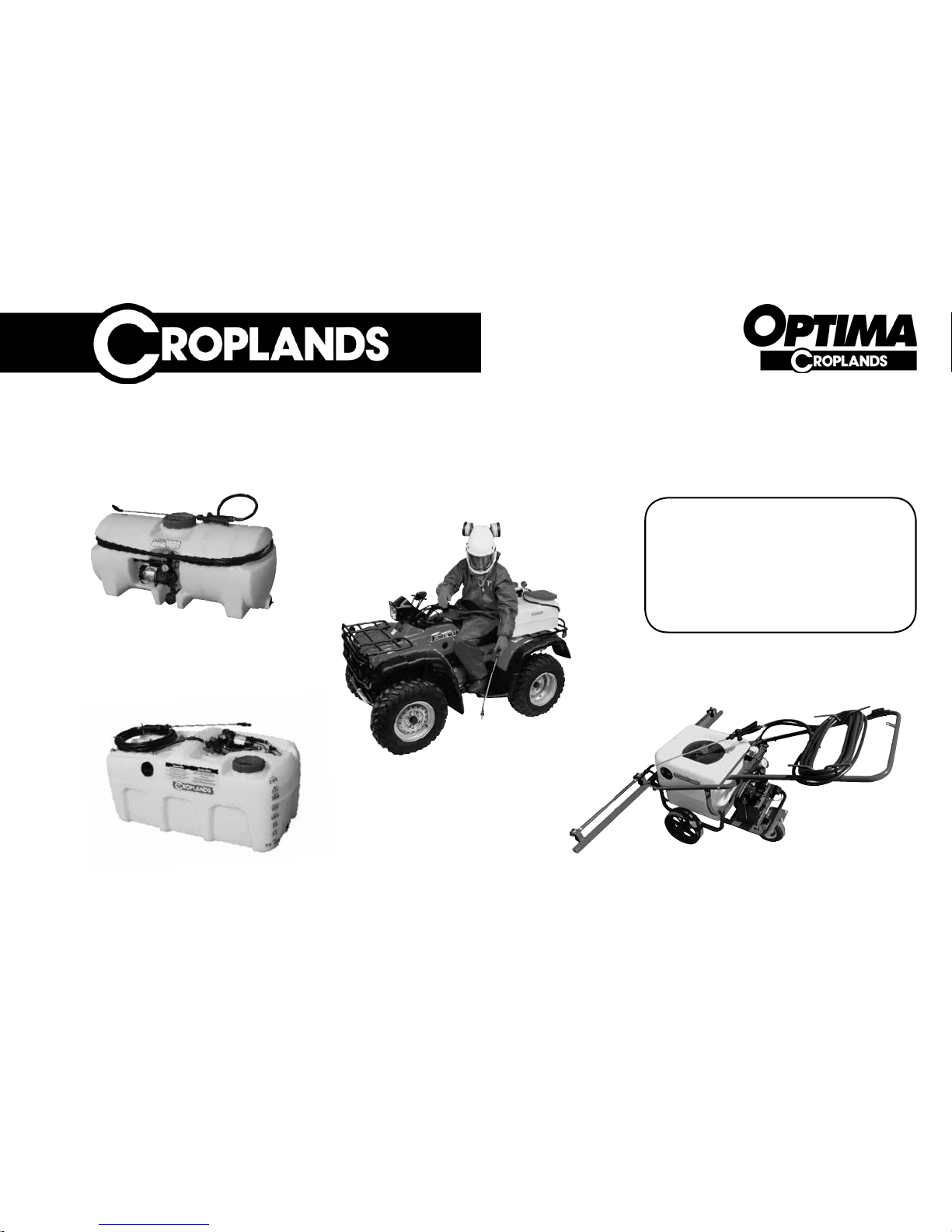
All types of the Optima range of 12 Volt sprayers are
pictured on the front cover and in the Identification
and/or in the Specification Chapter. Some model types
also have different options available.
Some features explained in this manual may not be
installed on your sprayer.
Please pass on this manual with the sprayer at the time
of resale for usage by the new owner.
Before Operating Your Sprayer
1 Before attempting to use your sprayer, make
sure you read the Operator’s Manual and
properly understand:
• All Safety Issues.
• Assembly & Installation instructions.
• Calibration of the sprayer.
• Sprayer Operation.
• Sprayer Maintenance.
2 Read and follow instructions on chemical
manufacturers' labels.
3 Always wear applicable protective clothing.
Read and understand this Operators’ Manual before
operating the CropPak sprayer.
Terminology
These terms/symbols used throughout this manual:
• NOTE - to convey useful operating
information.
• CAUTION - to highlight potential injury
or machinery damage.
• WARNING - to stress potential dangers
and the importance of
personal safety.
Indicates the strong possiblility of severe
personal injury or damage to machinery if
instructions are not followed.
WARNING
Highlights hazards, unsafe/unwise
practices which could cause injury, damage
to property, machinery or loss of crop yield
if instructions are not followed.
CAUTION
Refers to important and useful information
which should not be overlooked.
NOTE
For conditions of warranty and warranty
policy, please see the Warranty & Pre-
Delivery booklet provided with this
sprayer”
NOTE
Page 5

5
GP-OMCP12-B
Product Identification & Specifications Chapter 1
Product Identification 6
Model Specifications 7
• US30, 60 & 100 7
• US200, 400 & 800 9
• UM70 10
• UW50 11
Page 6

6
Product Identification & Specifications
GP-OMCP12-B
Product Identification
Where applicable, always use the Model and Serial
Number of the Optima 12 Volt Sprayer when requesting
service information or when ordering parts.
Early models or later models may use different parts,
or it may be necessary to use a different procedure for
specific service operations.
Sprayer Part & Serial Number
Always use the serial number of the Optima 12 Volt
Sprayer when requesting service information or when
ordering parts.
Where a serial plate is not provided, please use the
part number from the bar code affixed to this manual
or the Warranty & Pre-Delivery booklet.
Pump Model & Serial Number
The Pump Model & Serial Number is located on the
pump. This plate shows name of manufacturer, type
& model of pump, serial number, maximum voltage,
maximum amperage, maximum flow rate and maximum
working pressure of the pump. For further information
see the pump’s manual or Croplands website > Sprayer
Components.
Serial number plate. Model & Serial number of a Flojet 3000 pump.
Please supply the pump model number
as a reference when ordering pump spare
parts.
NOTE
Product Identification
For further information on Croplands
Sprayers, see
www. croplands.com.au
NOTE
Bar code.
Page 7

7
Chapter 1
GP-OMCP12-B
Model Specifications
US30, 60 &100.
US30, 60 & 100 Litre Models
30/60/100 litre CropPaks – practical spot sprayers for
a multitude of uses around the farm. Hook up to your
12 volt power source and get spraying.
For use in small trailers and/or utility vehicles, or 4wheel motorbikes.
Ensure your vehicle is rated for the weight of the sprayer
when full of liquid.
US100A 100 litre CropPak, with 12 volt on demand 7.6 L/min open-flow Triplex
pump, 6 metres of spray hose, spray
lance and long power lead with
on/off switch.
US100A/15 100 litre CropPak, with 12 volt on demand 15 L/min open-flow Triplex
pump, pressure regulator and gauge,
6 metres of spray hose, spray lance
and long power lead with on/off
switch.
Model Description
US30A 30 litre CropPak, with 12 volt on demand 7.6 L/min open-flow Triplex
pump, 6 metres of spray hose, spray
lance and long power lead with
on/off switch.
US60A 60 litre CropPak, with 12 volt on demand 7.6 L/min open-flow Triplex
pump, 6 metres of spray hose, spray
lance and long power lead with
on/off switch.
US60.
Ensure your vehicle is rated for the weight
of the sprayer when full of liquid. Failure
to do this may cause instability & serious
injury.
WARNING
US30.
Right:
US60 on ATV.
Page 8
8
Product Identification & Specifications
GP-OMCP12-B
7
Model Specifications
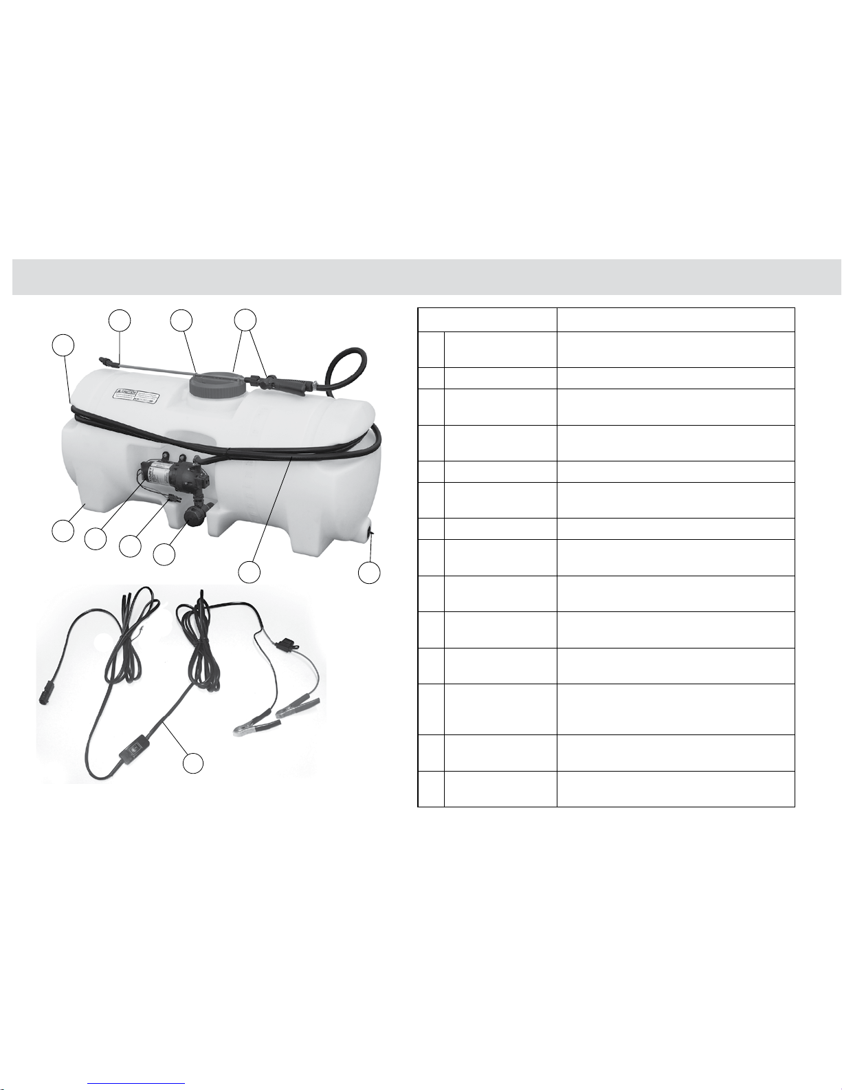
Feature Benefit
1
Cavity mounted
pump.
Total protection against the elements and damage.
Low pump position ensures excellent priming.
2
Translucent tank. Easy to see liquid level in the tank.
2
Rugged design,
locally made.
Rotomolded tank has uniform thickness and can
take high impact force.
2
UV stabilised tank. Excellent UV resistance. Many imported models
have no UV inhibitor in the material.
3
Large carry handles. Easy handling and for storing hose neatly.
4
Lance clips onto lid. Ensures neat storage and avoids lance dragging
on the ground.
4
Large filling lid. Helps prevent spillage when filling.
5
Large suction
filter,easy access.
Very large filtering area with easy-clean filter
screen. Simple and quick to access.
6
3-stage filtration. Large filling screen under lid; large suction filter;
pressure filter in lance handle.
7
Heavy-duty power
cable.
Long, heavy-duty 12 volt power lead with rockerswitch for easy hook-up to your battery.
8
Quick-clip power
connection.
High quality electrical connector to the pump with
waterproof plug for quick hook up and reliability.
9
Metal lance with
adjustable nozzle.
Superior to plastic, higher strength. Many
accessories are available to fit the lance - see
page 51.
10
Large drain. Easy-to-use, large ‘boat plug’ drain for quick
clean-out.
11
6 metre hose. 6 metres of high quality 20 bar rated spray hose
fitted.
3
11
10
8
5
2
1
6
4
9
Long (7 metre), fused, heavy duty power lead with rocker-switch
for easy hook-up to your battery.
US100 model.
Page 9

9
Chapter 1
GP-OMCP12-B
Model Specifications
Ensure your vehicle is rated for the weight
of the sprayer when full of liquid. Failure
to do this may cause instability & serious
injury.
WARNING
US200.
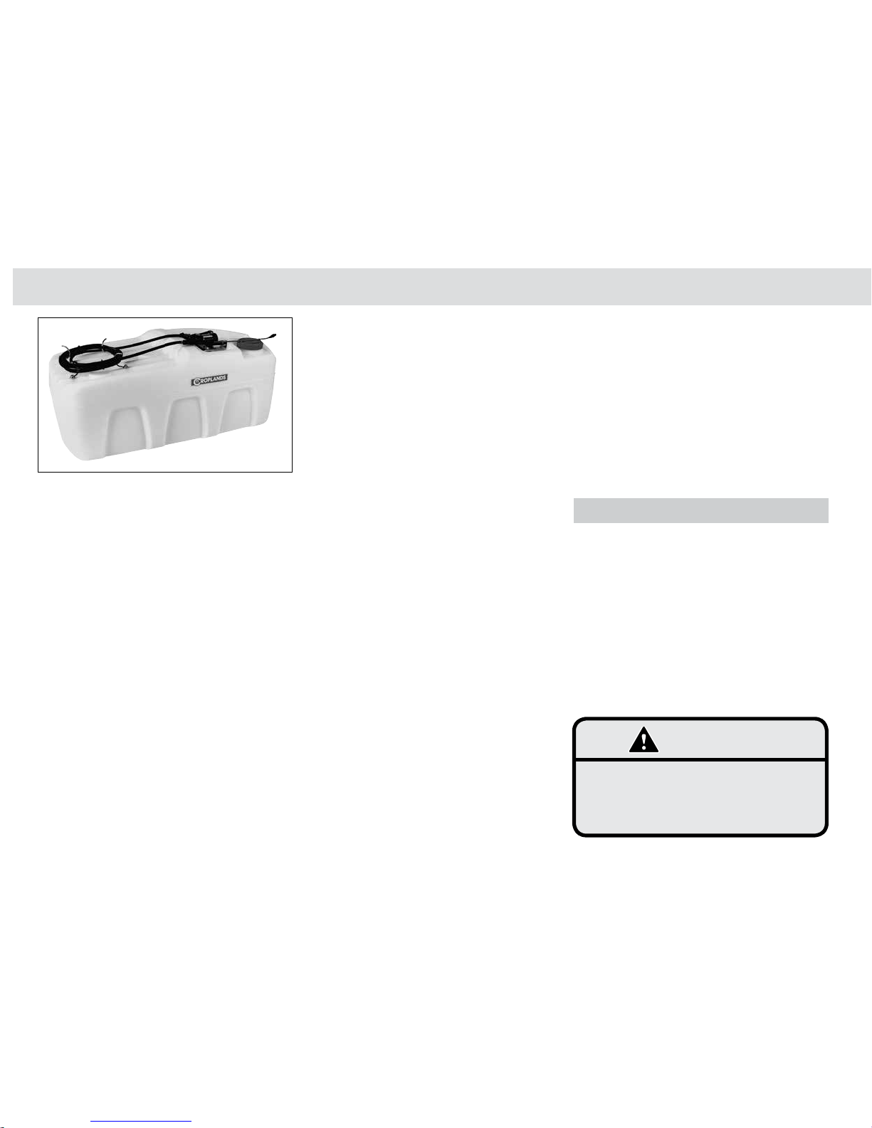
US200, 400 & 800 Litre Models
200/400/800 litre CropPaks – Larger model 12 volt
sprayers for farms and vineyards. For use on a ute tray,
UTV tray, tractor tray or trailer.
Ensure your vehicle is rated for the weight of the sprayer
when full of liquid.
US200/15 200 litre CropPak, with 12 volt
on-demand 15 L/min open-flow
Triplex pump, pressure regulator and
gauge, 3-way valve which enables
connection to a boom, 6 metres of
spray hose standard with spray
lance. Long power lead with on/off
switch provided.
Model Description
US200 200 litre CropPak, with 12 volt on demand 7.6 L/min open-flow Triplex
pump, 6 metres of spray hose, spray
lance and long power lead with on/off
switch.
Booms can be fitted to the models
using 15 L/min pumps (see photo
above), for use on utility vehicles and
some 4-wheel ATV’s. See Croplands
Optima Buyers Guide for details of 2,
3, 4 and 6 metre booms and mounting
kits for 15 L/min models.
US200/15 featuring a 3-way tap outlet for small booms.
Page 10
10
Product Identification & Specifications
GP-OMCP12-B
Model Specifications
US400/15 400 litre CropPak, with 12 volt
on-demand 15 L/min open-flow
Triplex pump, pressure regulator and
gauge, 3-way valve which enables
connection to a boom, 6 metres of
spray hose standard with spray
lance. Long power lead with on/off
switch provided.
US800/15 800 litre CropPak, with 12 volt
on-demand 15 L/min open-flow
Triplex pump, pressure regulator and
gauge, 3-way valve which enables
connection to a boom, 6 metres of
spray hose standard with spray
lance. Long power lead with on/off
switch provided.
Ensure your vehicle is rated for the weight
of the sprayer when full of liquid. Failure
to do this may cause instability & serious
injury.
WARNING
UM70 Litre Models
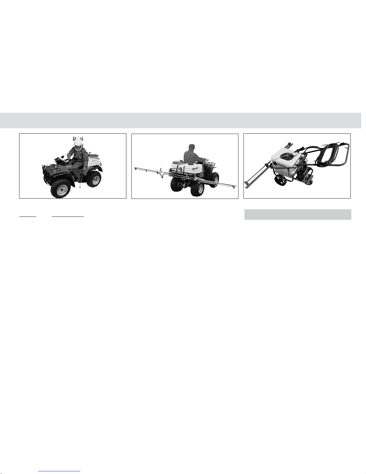
70 litre quad bike / ATV CropPak – 12 volt wrap around
sprayers for quad bike use.
Ensure your vehicle is rated for the weight of the sprayer
when full of liquid.
US400.
Page 11
11
Chapter 1
GP-OMCP12-B
Model Specifications
UM70/15/3B.
Model Description
UM70 70 litre CropPak, 12 volt on-demand
7.6 L/min Triplex pump, large filling
lid, 6 metre hose and adjustable
spray lance.
UM70/15 70 litre CropPak, 12 volt 15 L/min
Triplex pump with pressure
adjustment regulator fitted, large
filling lid, 6 metre hose and
adjustable spray lance, pre-plumbed
for boom.
UM70/15/3B 70 litre CropPak, 12 volt 15 L/min
Triplex pump with pressure
adjustment regulator fitted, large
filling lid, 6 metre hose and
adjustable spray lance and 3 metre
boom kit.
UM70/15/4B 70 litre CropPak, 12 volt 15 L/min
Triplex pump with pressure
adjustment regulator fitted, large
filling lid, 6 metre hose and
adjustable spray lance and 4 metre
boom kit.
UW50/2B.
UW50 Litre Model
50 litre “Greens” sprayer, 12 volt 7.6 L/min Triplex
pump with pressure regulator and gauge. 3-way valve
enables spraying via the 2 metre boom (with non-drip
nozzles) or adjustable spray lance (with 10 metres
of hose).
Three wheels provide excellent manoeuvrability for turf
or bowling green spraying. Battery included.
UM70.
Page 12

12
Product Identification & Specifications
GP-OMCP12-B
Page 13

13
GP-OMCP12-B
Assembly & Installation Chapter 2
Assembly Instructions 14
Battery Connection 15
Fitting the CropPak to a Carrier 15
Page 14
14
Assembly & Installation
GP-OMCP12-B
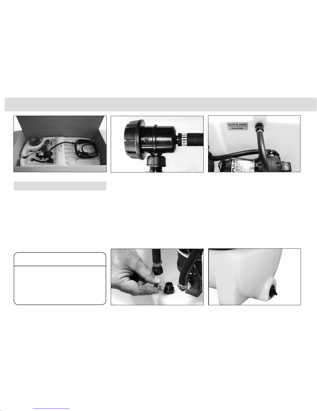
Unpack the Sprayer
CropPack Models - US30/60/100,
US200/400/800, UM70, UW50
The US30/60/100/200/400/800 models are supplied
fully assembled except for:
• Assembly of the lance (disassembled for
packing & transport).
• Connection to a 12 Volt battery.
• Fitting the unit to a vehicle (as required).
CropPak Assembly
Assembly Instructions
To assemble the CropPak sprayer:
1 Unpack the unit and check that nothing is missing
or has been damaged in transit.
2 Connect the lance to the hand grip and tighten
the flange.
3 Check all worm-drive clips for tightness (if
applicable).
4 Check and clean (if necessary) the suction filter:
• On UM70 models - Unscrew the filter, remove
and clean. Refit the filter & suction line and
tighten.
• All other models - Unscrew the suction filter
cap, remove and clean the filter screen. Refit
the screen & filter and re-tighten.
5 Check that the pressure line hose is connected.
6 Check the tank drain plug is fitted and sealed.
Unpack the sprayer.
Remove and clean suction filter (UM70 only).
Check & clean the suction filter.
Check the tank drain plug is sealed.
Whilst all precautions are taken in assembly
and testing, it is possible that some tank
filings remain in the lines. These will
accumulate in the suction filter when first
used. Therefore, clean the filter out after
initial use, and nozzles, if necessary.
NOTE
Refit the filter & suction line (UM70 only).
Page 15

15
Chapter 2
GP-OMCP12-B
CropPak Assembly
Connect the power leads to a 12 Volt battery. Connect the power lead to the pump.
Battery Connection
The Flojet pump must be connected directly to the +ive
and -ive terminals of a 12 Volt battery.
To Connect the CropPak sprayer to a 12 Volt battery:
1 Unpack the wiring loom (UP-119B).
2 Connect the power leads to a 12 Volt battery:
• The red (+ive) power lead to the positive
(+ive) battery terminal, and
• The black (-ive) power lead to the negative
(-ive) battery terminal.
The leads must be connected to a 12 Volt battery.
Failure to connect leads to a battery of the correct
voltage will cause damage to the electric motor.
3 Connect the power lead to the pump.
Fitting the CropPak to a Carrier
The free-standing design of the CropPak units allows
them to be used on many types of vehicles.
When using a CropPak on a vehicle, always strictly
adhere to the vehicle manufacturer’s load carrying
specifications.
To fit the CropPak onto a vehicle:
1 Place the CropPak onto the vehicle. If a stand
alone battery is being used, fit this also.
The leads must be connected to a 12
Volt battery. Failure to connect leads to a
battery of the correct voltage will cause
damage to the electric motor.
CAUTION
When using a sprayer on a vehicle, always
adhere to the vehicle manufacturer’s load
carrying specifications. Failure to do
this could result in serious damage and
injury
WARNING
Page 16
16
Assembly & Installation
GP-OMCP12-B
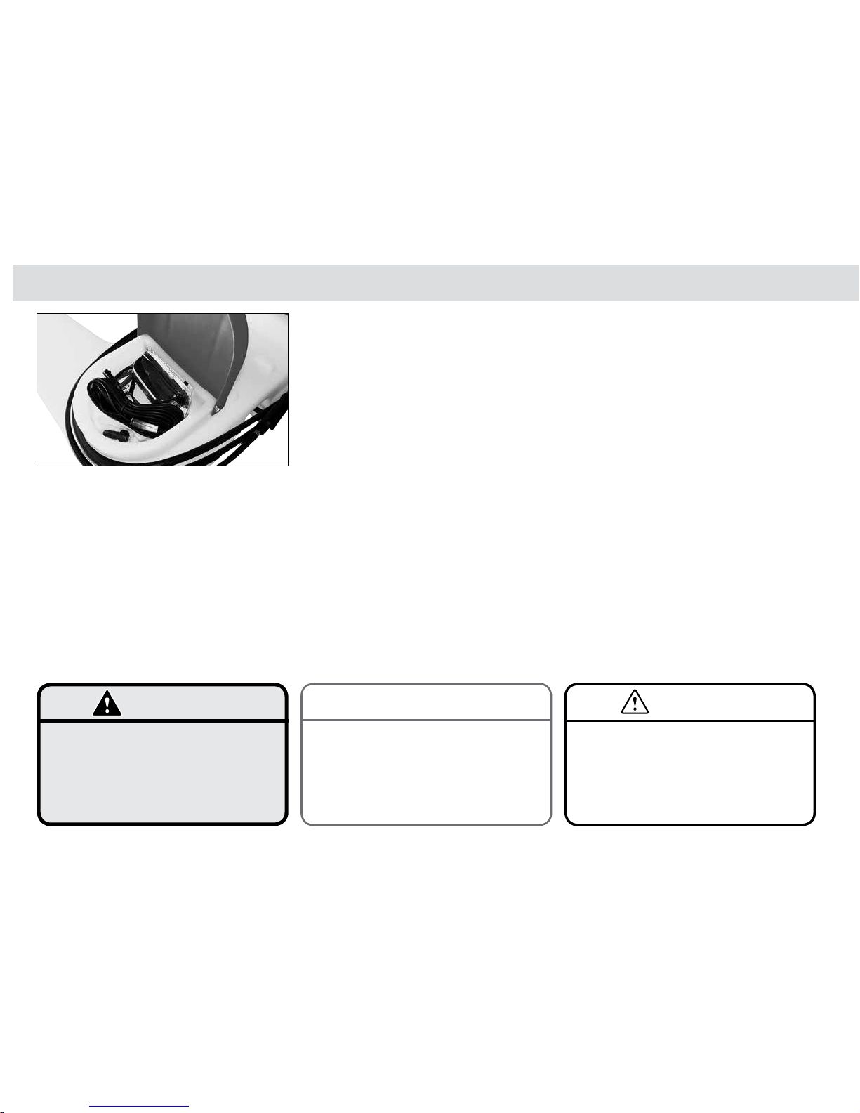
2 Secure the CropPak (and battery, if applicable) so
that they are not able to slide around or tip over
when the vehicle is moving.
Optional straps are available. The UM70 comes
supplied with a 4 metre strap.
3 Connect the CropPak power leads to the battery
terminals (on vehicle or stand alone) [see battery
connection instructions on the previous page].
To remove the CropPak from a vehicle:
1 Disconnect the CropPak wires from the battery
terminals.
2 If fastened, unfasten the CropPak (and battery, if
applicable) from the vehicle.
CropPak Assembly
3 Remove the CropPak from the vehicle and store
them in a suitable location, preferably under-
cover - protected from the sun and the weather.
If the CropPack is fitted to any ATV, two or
four wheel motorcycle, the CropPak MUST
BE secured with suitable self-locking carry
straps.
WARNING
The leads must be connected to a 12
Volt battery. Failure to connect leads to a
battery of the correct voltage will cause
damage to the electric motor.
CAUTION
Whilst all precautions are taken in assembly
and testing, it is possible that some tank
filings remain in the lines. These will
accumulate in the suction filter when first
used. Therefore, clean the filter out after
initial use, and nozzles, if necessary.
NOTE
UM70 includes a tie down strap.
Page 17

17
GP-OMCP12-B
Calibration Chapter 3
Calibration 18
• Spot Sprayer 19
• Boom Sprayer 22
Page 18
18
Calibration
GP-OMCP12-B
Sprayer calibration is one of the single most important
factors in establishing the correct application rate of
the sprayer.
Without calibration it is not possible to know the actual
rate of spray application.
Calibration
Today, we must strive for the most efficient use of spray
chemicals for effective pest and disease control.
Increasing costs, as well as consumer and public
pressures to minimise residues, requires us to achieve
the target application rate (uniform spray coverage
without over or under spraying).
Applying the correct amount of chemical to a crop is
only possible if the:
• Sprayer is calibrated correctly (this chapter).
• Sprayer is operated correctly (see chapter 4).
• Sprayer is maintained correctly (see chapter 5).
Correct chemical application rate can only be achieved
if the variables of spray application are measured and
controlled:
• Distance, time & working width are measured.
• Liquid & chemical volume applied.
This is done through sprayer calibration.
Spot Sprayer Calibration
Do not operate a sprayer without
calibration or before calibration has been
completed.
Failure to calibrate a sprayer before
operating may result in ineffective or crop
damaging spray application.
CAUTION
Page 19

19
Chapter 3
GP-OMCP12-B
Spot Sprayer Calibration
CropPack sprayers are most commonly used for spot
spraying using a hand gun with a single variable cone
or flat fan nozzle.
Precise application rates are not usually achieved with
hand guns because the application rate is entirely
dependent on the operator.
Two steps are recommended for calibrating a spot
sprayer:
1 Choose the appropriate nozzle.
2 Check the nozzle operates correctly.
Step 1
Choose the Appropriate Nozzle
The nozzle used should be appropriate for the chemical
being used. The standard adjustable ConeJet should
suffice for general Glyphosate-based formulations
& applications. Follow the chemical manufacturer’s
recommendation for any specific nozzle requirements
as per the manufacturers label.
The standard CropPak lance has a removable cap,
the adjustable ConeJet can be removed and most 80
and 110 degree flat fan nozzles can then be used with
the cap & seal.
Pump Specification
The nozzle chosen must be within the flow capability
of the pump on your CropPak.
CropPack sprayers are fitted with pumps that operate
within a pressure range. The pump model FL3501-506
is a Triplex diaphragm pump with an internal bypass
which allows the pump to work with a nozzle within a
range of flow from approximately 1 litre per minute to
2.5 litres per minute in the correct pressure range for
the pump.
The FL3501 Series pump is fitted with an inbuilt
automatic shut off pressure switch which will switch
the pump:
• ON, when low pressure is detected, and
• OFF, when the preset high pressure is
reached.
Spot Sprayer Calibration
Spot spraying application.
Page 20

20
Calibration
GP-OMCP12-B
The larger pump models - FL3521-139 and occasionally
the FL4300-143 - which are fitted on CropPaks designed
for both spot spraying and small boom spraying have
a pressure & flow regulator fitted to allow the operator
to adjust the pressure & flow to match the nozzle
requirement for spot spraying. Generally this is within
the 1 litre per minute to 2.5 litres per minute range.
An oversized nozzle will result in insufficient pressure
and an ineffective spray pattern.
An undersized spray nozzle may cause the pump
pressure switch to cycle on and off too frequently and
create a pulsating flow from the pump.
All reputable nozzle manufacturers follow the ISO
colour-coded system for nozzle outputs. Nozzle
output charts for specific nozzles are available from
Croplands.
Step 2
Check the Nozzle Operates
Correctly
1 Fill the sprayer tank with clean water making sure
the lid filter is in place.
2 Connect the sprayer power leads to a 12 volt
battery (see battery connection instructions in
chapter 2).
3 Switch On the pump.
Check the current Croplands Optima
Buyers Guide for Nozzle information.
NOTE
Spot Sprayer Calibration
Always only use clean water when
calibrating or checking a sprayer. Never
calibrate with and toxic chemical present
in the tank. Failure to follow this instruction
can lead to poisoning and serious
illness.
CAUTION
Fill the spray tank with the lid filter in place.
Nozzle spray patterns and spray angles
should be visually checked for accuracy
and the nozzle replaced if not spraying
correctly.
NOTE
Page 21
21
Chapter 3
GP-OMCP12-B
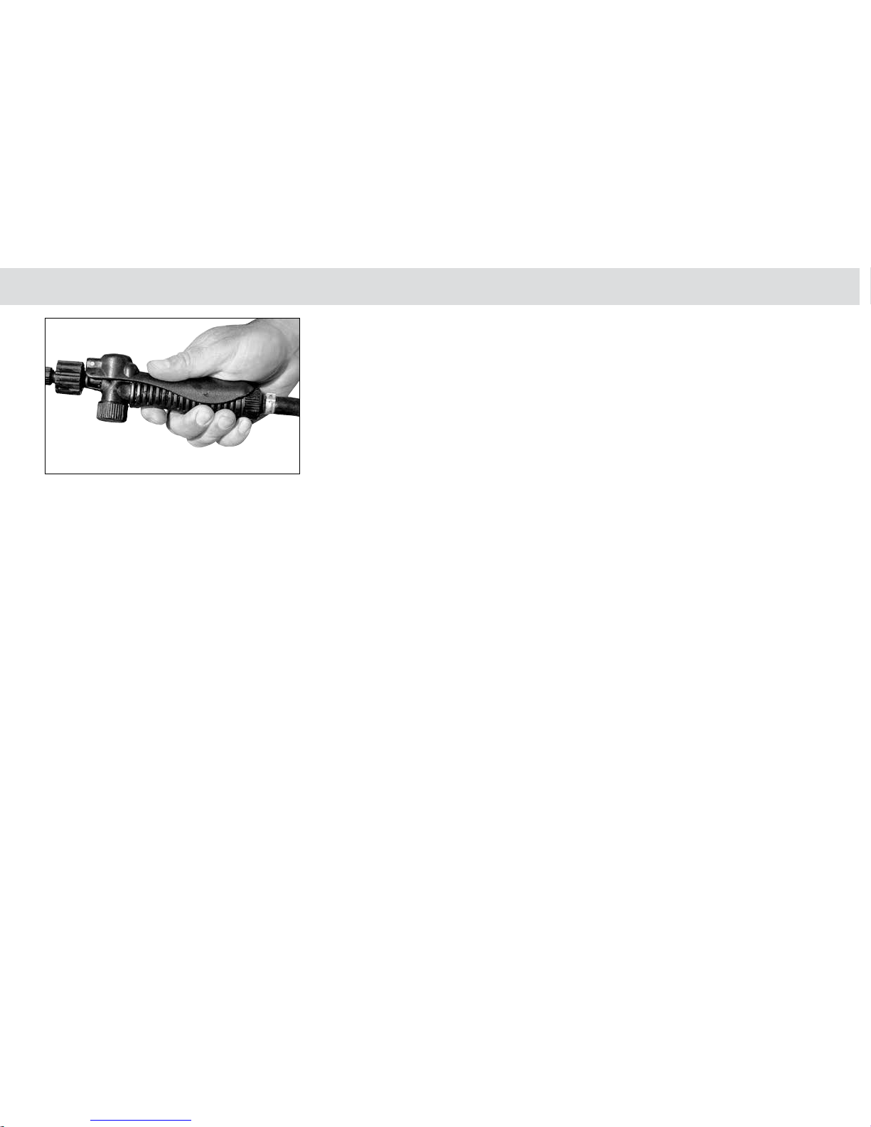
Hold down the hand grip lever to spray
Spot Sprayer Calibration
4 Hold down the hand grip lever to spray and check
that the:
• Spray pattern is even.
• Pump pressure is sufficient and that the pump
is not cycling On and Off too often.
• If using a variable cone nozzle, adjust the
cone to make the spray pattern required.
5 Release the hand grip lever to stop spraying.
6 Switch Off the pump.
7 If necessary, make any adjustments and re-
check.
When the nozzle operates correctly, the sprayer is
ready for operation.
Page 22
22
Calibration
GP-OMCP12-B
Boom Sprayer Calibration
Boom Spraying
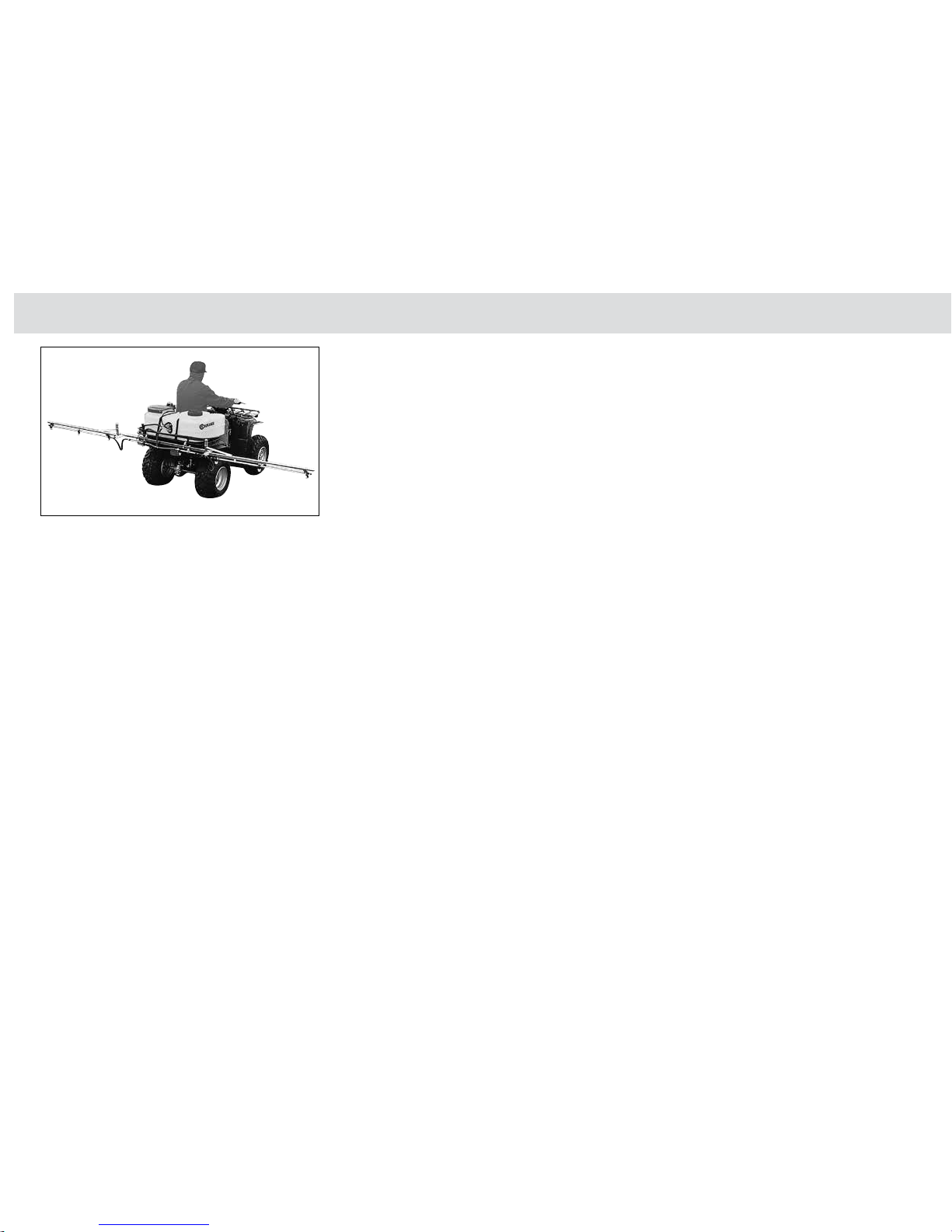
Some CropPak models also have booms supplied
(for example UM70/3B, UM70/4B & UW50/2B) and
most CropPak models with larger pumps can have, if
required, a boom up to 4 metres fitted.
Each Croplands boom is fitted standard with non-drip
nozzle bodies so that when the liquid flow is switched
off, the bodies will not drip.
Also supplied on our booms are AirMix air-induction
ultra low drift nozzles - now an industry standard to
reduce the likelihood of spray drift.
The liquid flow to the boom can be stopped & started as
required (such as when turning at headlands or where
the operator does not want to spray) by using the switch
integrated into the standard electrical loom that runs
from the pump to the vehicle battery.
To ensure the right application of herbicide or crop
protection product is applied to the target crop, the
user should calibrate the boom to ensure the correct
application rate is used for the chemical being used.
This information (spray target rate and spray quality)
is usually supplied by the chemical manufacturer on
their product label. Alternatively, a trained agronomist
should be consulted.
Note that the CropPak range would generally only
be suitable for spraying up to 8-10 Km/hr - above this
speed the 12-volt pumps will struggle to supply enough
flow to the nozzles.
Part of the calibration process is to determine the
maximum flow required to meet the required target
spray rate, and this information can be used to
determine what speed of travel will best suit your
application.
In the case of the UW50/2B, the speed will likely be a
normal walking speed of approximately 4 km/h, which
is well within the limits of the 12-volt pump fitted on
the unit.
Boomspraying.
Page 23

23
Chapter 3
GP-OMCP12-B
Calibration
There are 3 things you require to know or check:
1 Speed of travel,
2 Nozzle spacing, and
3 Nozzle pressure, or nozzle output in L/min.
1 Speed of travel
Check your ute / tractor / ATV speed. If you have an
accurate speedometer, this will suffice. If not, measure
the distance you have travelled in one minute in metres,
and divide this by 16.7,
e.g. 120 metres travelled in one minute ÷ 16.7
= 7.18 km/hour.
If this is impractical, measure the distance travelled in
30 seconds, double it, and then divide by 16.7.
Repeat at least twice, from a running start, to ensure
accuracy.
2 Nozzle spacing
All Croplands booms suitable for CropPak sprayers
have 50cm nozzle spacing.
Boom Sprayer Calibration
Page 24

24
Calibration
GP-OMCP12-B
3 Pressure or flow
If your sprayer has an accurate pressure gauge, set it
to the desired pressure for the type of nozzle you are
using. If you are unsure of this, generally 2 bar (30 psi)
is ideal for most nozzles.
If you do not have an accurate gauge, measure the
nozzle output, in Litres per minute with an accurate
measuring jug & stopwatch.
Use the following chart to determine your Litre per
hectare (L/ha) application rate.
NOZZLE BAR L/MIN Km/hr
4 5 6 7 8 9 10 12 16
110-02
1 0.46
1.5 0.56
2 0.65 78.0
3 0.79
4 0.91
In the example above,:
- The nozzle is a 110° 02 nozzle (yellow),
- At 2 Bar spraying pressure, it has an output
of 0.65 L/min, and
- At 10 km/hr you will apply 78 litres per hectare
of water,
- With the nozzles at 50cm spacing.
Multiple nozzles do not affect the outcome - if you
have eight nozzles on your boom your application is
the same per hectare.
To find more information on how to calibrate a boom
for varying application rates,:
• Refer to the Croplands web site at
www.croplands.com.au or
• Contact the Croplands Customer Service or
Technical Support: Phone 1300 650 724.
This chart illustrates a 110° 02 nozzle (yellow) operating with 2 Bar spraying pressure giving an output of 0.65 L/min and
travelling at 10 km/hr applying 78 litres per hectare of water using 50cm nozzles spacing.
Boom Sprayer Calibration
Page 25

25
GP-OMCP12-B
Operating the Sprayer Chapter 4
Initial Start-Up Procedure:
• For models without Regulator Kit 26
• For models with Regulator Kit 28
Adding Chemical to the Spray Tank 31
Tank Agitation 32
Operating the Hand Gun 33
Hand Gun Spraying Method 34
Boom Spraying 35
Daily Start Up Procedure 36
Operating Pointers 37
Useful Formula 37
Daily Clean & Flush the CropPak 38
Using Tank & Equipment Cleaners 39
Safety Instructions 40
Page 26
26
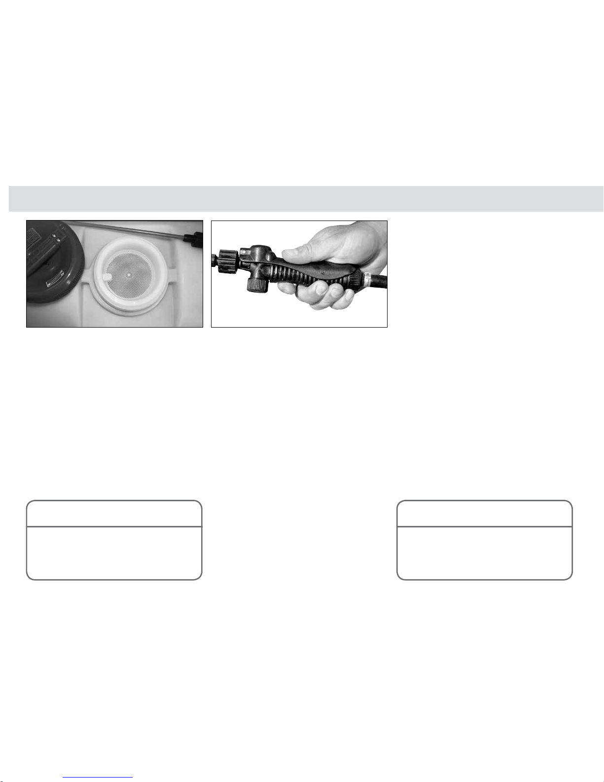
Hold down the hand grip lever to activate & prime the pump.Fill the spray tank with the lid filter in place.
Operating the Sprayer
GP-OMCP12-B
Initial Start-Up Procedure -
for models without Regulator kit
Initial Start-Up Procedure
After assembly and installation procedures are
complete, it is important to check that the pump will
prime and operate properly.
To initally start operating the sprayer:
1 Check that the spray tank is clean.
2 Check that the suction line filter is clean.
3 Check all plumbing and fittings are tight and not
damaged or leaking.
4 Fill the sprayer tank with clean water - making
sure the basket filter is in place when filling.
5 Connect the sprayer power leads to a 12 volt
battery (see battery connection instructions
in chaper 2).
6 Switch On the pump.
This will normally activate the Flojet pump to
automatically prime itself and run until the preset
shut-off pressure is reached.
7 Hold down the hand grip lever. This will normally
activate the Flojet pump to fully prime and pump
water through the spray line.
If the pump fails to prime ...
On initial start-up, the 12 Volt pump may fail
to automatically prime.
When the inside valves of the pump are dry,
the pump will not automatically prime as the
valves do not seal off the air.
This can occur when the:
• Pump is new,
• Pump has not been properly flushed with
clean water after use, or
• Pump has not been used for a period
of time.
This problem is easily fixed by wetting the valves.
To wet the pump valves:
a) Disconnect the spray lance from the gun itself.
b) Squeeze the gun trigger so liquid flows
unrestricted from the gun body. This liquid can
be directed into the tank opening. Flow may
take a few seconds.
Do not add chemical to the tank until
you have checked the unit is fully
operational.
NOTE
It is important to check that the pump is
fully primed and operates properly. If this
is not done the sprayer will not function
properly.
NOTE
Page 27
27
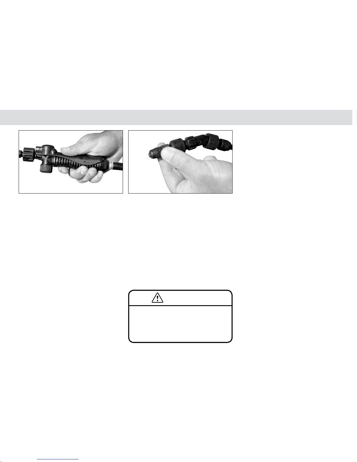
Hold down the hand grip lever to prime & operate the sprayer. Adjust the variable cone nozzle for the required spray pattern.
Chapter 4
GP-OMCP12-B
Initial Start-Up Procedure - for models without Regulator kit
c) Reconnect the spray lance to the gun.
This procedure should successfully prime the
pump.
8 Hold down the hand grip lever to operate the
sprayer.
Each time the hand gun lever is held down, the
pressure drop is sensed by the pump. The pump
then automatically switches itself On & Off as
required to maintain pressure.
Pressure build-up automatically shuts off the
pump, and pressure drop automatically restarts
the pump.
9 While the hand gun is spraying, check that the:
• Nozzle spray pattern is even,
• Pump pressure is sufficient and that the
pump is not cycling On and Off too often,
• If using a variable cone nozzle, adjust the
cone for the required spray pattern.
10 Release the hand grip lever to stop spraying.
11 Switch Off the power to the pump when the
initial start-up procedure is completed.
12 If required, make the necessary adjustments and
re-check the sprayer operation.
After the initial start-up procedure is successfully
completed, the sprayer is ready for operation.
When the tank becomes empty, the pump
will continue to run. Running the pump
dry temporarily will not cause damage.
However, avoid letting the pump run dry
CAUTION
Page 28

28
Manually adjust the Pressure Regulating Valve to set the
desired pressure.
Operating the Sprayer
GP-OMCP12-B
Hold down the hand grip lever to activate & prime the pump.Fill the spray tank with the lid filter in place.
Initial Start-Up Procedure -
for models with Regulator kit
Initial Start-Up Procedure
If you have purchased your CropPak with a larger
(15 l/min) pump, it will have a pressure regulator to
regulate pressue and flow, instead of a pressure switch
on the pump.
After assembly and installation procedures are
complete, it is important to check that the pump will
prime and operate properly.
To initally start operating the sprayer:
1 Check that the spray tank is clean.
2 Check that the suction line filter is clean.
3 Check all plumbing and fittings are tight and not
damaged or leaking.
4 Fill the sprayer tank with clean water - making
sure the basket filter is in place when filling.
5 Connect the sprayer power leads to a 12 volt
battery (see battery connection instructions
in chaper 2).
6 Switch On the pump.
This will normally activate the Flojet pump to
automatically prime itself.
7 Hold down the hand grip lever. Once the unit is
spraying clean water, adjust the Pressure
Regulating Valve (PRV) to the desired pressure,
using the pressure gauge to determine the
operating pressure.
8 When not spraying for any length of time, switch
the pump off or disconnect the unit from the
battery.
Do not add chemical to the tank until
you have checked the unit is fully
operational.
NOTE
As there is no pressure switch fitted, the
15 l/min Flojet pump will continuously
run bypassing liquid to the tank while the
spray gun is closed.
NOTE
When not spraying for any length of time,
switch the 15 l/min Flojet pump off or
disconnect the unit from the battery.
NOTE
Page 29
29
Chapter 4
GP-OMCP12-B
Initial Start-Up Procedure - for models with Regulator kit
If the pump fails to prime ...
On initial start-up, the 12 Volt pump may fail
to automatically prime.
When the inside valves of the pump are dry,
the pump will not automatically prime as the
valves do not seal off the air.
It is important to check that the pump is
fully primed and operates properly. If this
is not done the sprayer will not function
properly.
NOTE
The 15 l/min Flojet Pump is designed to
operate at a maximum of 2.8 Bar (40 psi).
DO NOT EXCEED THIS PRESSURE or
damage to the pump may occur.
NOTE
This can occur when the:
• Pump is new,
• Pump has not been properly flushed with
clean water after use, or
• Pump has not been used for a period
of time.
This problem is easily fixed by wetting the valves.
To wet the pump valves:
a) Disconnect the spray lance from the gun itself.
b) Squeeze the gun trigger so liquid flows
unrestricted from the gun body. This liquid can
be directed into the tank opening. Flow may
take a few seconds.
c) Reconnect the spray lance to the gun.
This procedure should successfully prime the
pump.
Page 30
30
Operating the Sprayer
GP-OMCP12-B
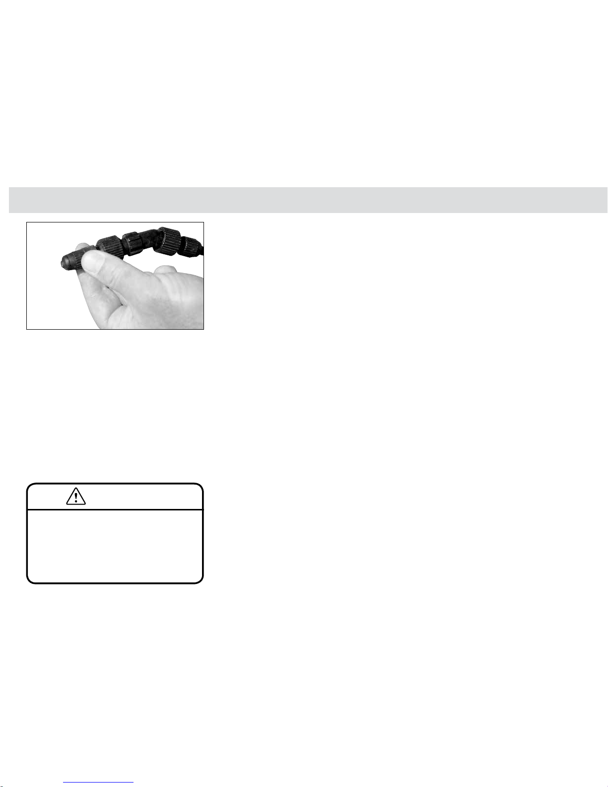
Adjust the variable cone nozzle for the required spray patter n.
9 While the hand gun is spraying, check that the:
• Nozzle spray pattern is even,
• Pump pressure is constant and within the limit
of the pump's maximum pressure rating (3.4
Bar [50 psi]),
• If using a variable cone nozzle, adjust the
cone for the required spray pattern.
10 Release the hand grip lever to stop spraying.
11 If required, make the necessary adjustments and
re-check the sprayer operation. Use the power
switch to turn the power Off.
After the initial start-up procedure is successfully
completed, the sprayer is ready for operation.
When the tank becomes empty, the pump
will continue to run. Running the pump
dry temporarily will not cause damage.
However, avoid letting the pump run dry
for long periods of time because damage
may occur from over heating.
CAUTION
Initial Start-Up Procedure - for models with Regulator kit
Page 31
31
Chapter 4
GP-OMCP12-B
Adding Chemical to the Spray Tank
Adding Chemical to the Spray
Tank
Chemical should only be added to the spray tank after
initial start up procedure is complete.
The steps for adding chemical to the tank are:
1 Calculate the amount of chemical required.
2 Part fill the spray tank with water.
3 Measure and pre-mix the chemical.
4 Add the pre-mixed chemical to the tank.
Step 1
Calculate the Amount of Chemical
Required
To add the correct amount of chemical to a tank, it
is necessary to calculate the amount of chemical
required.
The method of calculating the amount of chemical
required for the sprayer tank is dependent on the
chemical rate recommendations. Use the information
supplied on theh chemical label to determine the tankmix concentration.
If you are unsure of the mix required, ALWAYS check
with a qualified advisor or the supplier of the chemical
you intend to use.
Be sure to mix only enough spray mixture
to cover the area required. Mixing too
much chemical creates unnecessary
waste and costs.
NOTE
Do not add chemicals to the spray tank
until the initial start-up or daily start-up
procedure has been carried out. This
avoids having a tank full of toxic chemical
and then finding a sprayer problem.
CAUTION
Page 32
32
Operating the Sprayer
GP-OMCP12-B
Adding Chemical to the Spray Tank
Step 2
Part Fill the Spray Tank with Water
Part fill the sprayer tank with clean water.
Use fresh water (preferably rainwater), free of
suspended organic matter or clay. Some chemicals
are deactivated when they contact these materials.
Ensure water quantity is sufficient to allow correct
product blending.
Step 3
Measure & Pre-Mix the Chemical
Read and follow the instructions on the chemical
manufacturers label before mixing & adding chemicals
to the spray tank.
Chemicals should be accurately measured and
thoroughly premixed in a separate container before
adding to the spray tank:
1 Measure out the required liquid chemical in a
graduated measuring cylinder or bucket.
2 Add chemical to a small volume of water in a
container and thoroughly mix the chemical.
Tank Agitation
It is important to use chemicals that naturally remain
in solution while in a CropPak spray tank.
After chemicals have been added to most CropPak
sprayer, the tank can only be agitated by:
• Rocking the tank (with the lid lid firmly in
place), or
• Placing the hand gun lance into the tank liquid
and pressing the hand gun lever.
Only the sprayers fitted with the 4300 & 3521 Series
pumps and regulator kit have a bypass to provide
continuous tank agitation while the pump is operating.
Always follow chemical label
instructions.
CAUTION
Should chemical come in contact with skin
immediately rinse off with water. Always
follow chemical label safety instructions.
CAUTION
Page 33

33
Place the lance into the lid storage clips.
Chapter 4
GP-OMCP12-B
Operating the Hand Gun
Step 5
Operating the Hand Gun
After chemical has been added to the tank, the sprayer
is ready for operation.
To operate the hand gun:
1 Make sure the sprayer power leads are
connected to a 12 volt battery (see battery
connection instructions in chaper 2).
2 Switch On the pump.
This will normally activate the Flojet pump to run
until the preset shut-off pressure is reached.
Do not to use chemicals which settle
without adequate agitation in the tank of
CropPak sprayers except for those fitted
with a 4300 & 3521 series pumps and
regulator kit.
NOTE
3 Aim the nozzle at the target area and hold down
the hand grip lever to spray the target.
Move the nozzle as required to completely spray
the target.
Use the hand gun trigger to turn the spray On &
Off as required.
4 When spraying is finished, place the lance into
the storage clips provided on the tank lid.
Switch off the pump or disconnect the power
leads from the battery.
Always wear approved safety clothing and
protective respiratory equipment when
spraying.
CAUTION
Step 4
Add the Chemical to the Tank
Always make sure the filling basket is in place when
adding water or chemical to the tank.
To add the premixed cheical to the tank:
1 Add the pre-mixed chemical to the tank,
thoroughly rinsing the chemical pre-mix container
and adding the rinse to the tank.
2 Top up the tank with water to the required volume.
3 Close the tank lid securely.
Page 34
34
Operating the Sprayer
GP-OMCP12-B
Operating the Hand Gun
Hand Gun Spraying Method
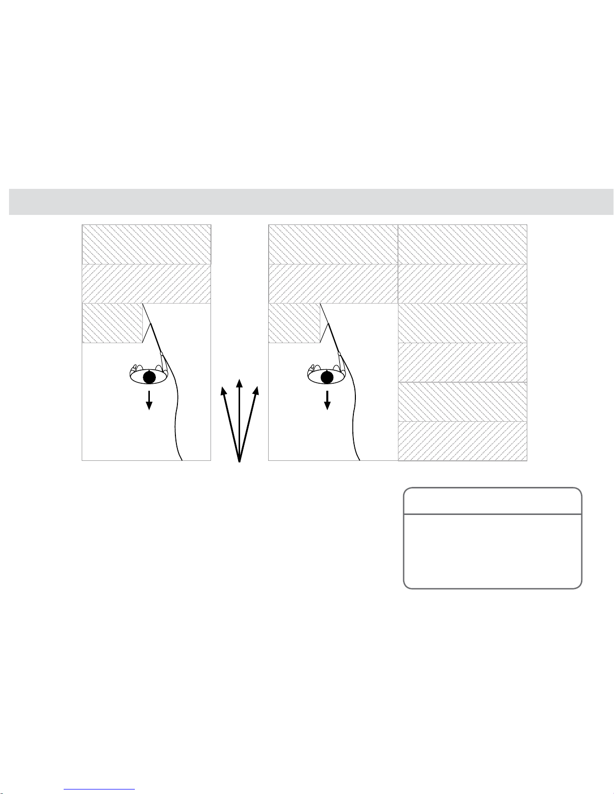
It is always preferable to spray with your back toward
the wind direction so that the wind carries spray away
from the operator.
The operator should where possible, avoid walking on
previously sprayed areas to avoid unnecessary fumes
and contamination.
Operate with the sprayer situated behind the operator
so that the hose from the sprayer can be kept on
unsprayed areas.
This is important because the operator usually has to
handle, extend and rewind the hose many times, as he
shifts from area to area.
If the hose is kept relatively free from spray contamination
there is less exposure to chemical contamination.
In small areas, spray across the area &
move back toward the wind.
In larger areas, divide the area into smaller segments & move back toward the wind
keeping track of the area sprayed to avoid under or overspraying.
It is recommended to keep the hose
from the sprayer on unsprayed ground
& uncontaminated from the spray.This
minimises contaminants on the hose
minimises exposure to chemicals when
handling and rewinding the hose.
NOTE
Page 35

35
Chapter 4
GP-OMCP12-B
Boom Spraying
Some CropPak models also have booms supplied
(for example UM70/3B, UM70/4B & UW50/2B) and
most CropPak models with larger pumps can have, if
required, a boom up to 4 metres fitted.
Each Croplands boom is fitted standard with non-drip
nozzle bodies so that when the liquid flow is switched
off, the bodies will not drip.
Also supplied on our booms are AirMix air-induction
ultra low drift nozzles - now an industry standard to
reduce the likelihood of spray drift.
The liquid flow to the boom can be stopped & started as
required (such as when turning at headlands or where
the operator does not want to spray) by using the switch
integrated into the standard electrical loom that runs
from the pump to the vehicle battery.
To ensure the right application of herbicide or crop
protection product is applied to the target crop, the
user should calibrate the boom to ensure the correct
application rate is used for the chemical being used.
See Chapter 3 for Calibration instructions.
This spray target rate and spray quality information
is usually supplied by the chemical manufacturer on
their product label.
Alternatively, a trained agronomist should be
consulted.
Boom Spraying
Page 36

36
Fill the spray tank with the lid filter in place. Hold down the hand grip lever to activate & prime the sprayer. If fitted, adjust the pressure relief valve to obtain the
required pressure.
Operating the Sprayer
GP-OMCP12-B
Daily Start Up Procedure
A careful, common sense approach to water quality,
mixing of chemicals and care of filters, hoses and tank
will ensure trouble free spraying.
To ensure trouble free operation, follow the procedure
below at the start of each day:
1 Ensure that no solids enter the system to block or
damage pump or nozzles.
2 Check that suction line filter is clean and not
damaged. It should be checked & cleaned
regularly.
Be careful not to damage or deform the mesh
or O-Ring while cleaning and refitting the suction
line filter.
If a filter screen is damaged, replace with a new
screen.
3 Put enough clean water into the spray tank to
operate the pump and hand gun.
4 Activate the pump and ensure it primes correctly -
hold the hand grip lever down, until the hand gun
sprays steadily.
5 If fitted, adjust the pressure relief valve to obtain
the required pressure.
Excess liquid will bypass back to the tank.
Once the pressure is set, it is normal for minor
fluctuations to show on the pressure gauge when
switching the hand gun On & Off.
6 Check that all hoses, hose clamps and
connections do not leak.
Repair or replace damaged components.
7 Read and follow the instructions on the chemical
manufacturers label before mixing and adding
chemicals to the spray tank.
8 Add chemical to the tank and proceed with your
spray application.
Do not add chemicals to the spray tank
until the initial start-up or daily start-up
procedure has been carried out. This
avoids having a tank full of toxic chemical
and then finding a sprayer problem.
CAUTION
Daily Start Up Procedure
Page 37

37
Chapter 4
GP-OMCP12-B
Operating Pointers
While spraying continually observe that:
1 Adequate operating pressure is being maintained.
2 Your hand gun coverage is correct and constant
for effective cover.
3 The nozzle is operating correctly.
4 Periodically check and clean filters.
5 Avoid going too slow because over application
will occur.
Conversely, avoid going to fast because under
application will occur.
Useful Formula
1 Calculating the Tank Spray Area
Use this formula to calculate the area each tank full of
spray will cover.
Area Covered (ha) =
Tank Volume (litres)
Spray Application Rate (l/ha)
eg, 250
100
= 2.5 hectares.
2 Calculating the Total Liquid Volume
Required
Use this formula to calculate the amount of spray liquid
required to spray a given area.
Total Liquid Volume Required (litres) =
Area (ha) x Spray Application Rate (l/ha)
eg, 2 x 100
= 200 litres.
Operating Pointers
Page 38
38
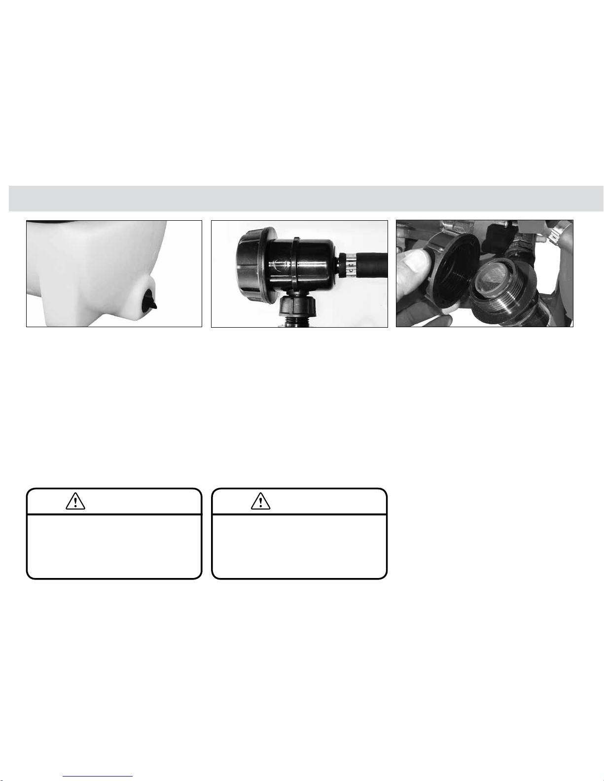
Remove the tank drain plug. Remove & clean the suction line filter, then reassemble.
Operating the Sprayer
GP-OMCP12-B
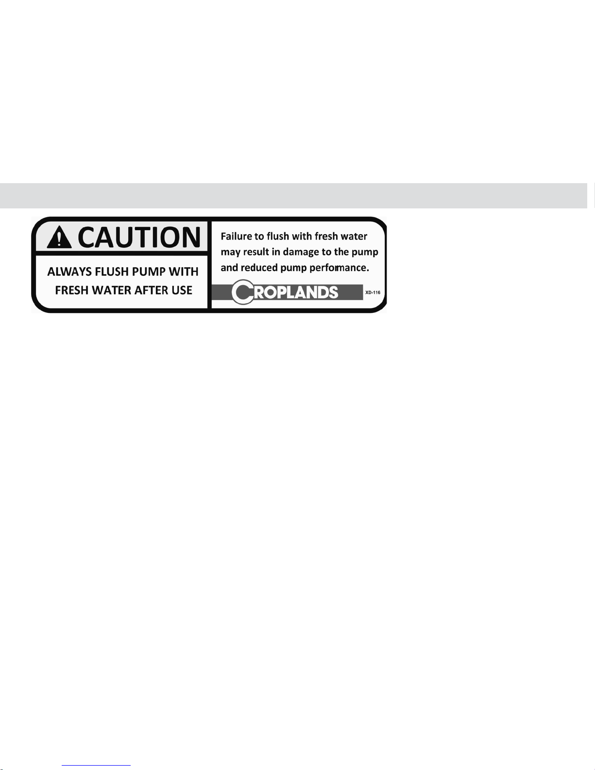
Clean & Flush the CropPak
2 After chemicals have drained from the main tank,
thoroughly rinse out the tank.
3 Remove and thoroughly clean the suction line
filter & reassemble.
4 Close the tank drain valve and add clean water
to the tank to thoroughly flush the lines, pump
and spray gun (& boom if fitted).
5 Switch On the pump.
Clean & Flush the CropPak
The CropPak sprayer should be thoroughly cleaned
and flushed:
• Between chemical changes, and
• At the end of each day’s spraying.
To completely flush and clean the sprayer:
1 Remove the tank drain plug to drain spray
mixture from the tank.
Ensure drained mixture is disposed of as required
by law. Read the chemical instructions.
6 Hold down the hand grip lever until all mixture
is flushed out of the hose and hand gun.
7 On completion of flushing, release the trigger of
the hand gun and turn the power switch Off.
8 Repeat steps 1 to 7 to more completely
remove chemical residue from the tank and
sprayer system.
9 Wash/hose down the outside of the sprayer.
Always ensure the site for flushing
and cleaning the sprayer meets with
environmental and statutory regulations.
CAUTION
If you experience heavy frosts in you area,
run the pump until the spray lines are
dry after use. This will prevent damage
from water freezing in the spray lines and
pump.
CAUTION
Check & clean the suction filter.
Page 39
39
Chapter 4
GP-OMCP12-B
Using Tank & Equipment Cleaners
Using Tank & Equipment
Cleaners
If a cleaning agent is required (refer to chemical label),
first completely flush the Sprayer with water as outlined
on the previous page.
To use the tank & equipment cleaner:
1 Fill the spray tank approximately half full of fresh
water.
2 Add cleaning agent (use according to the
manufacturer's instructions).
3 Switch on the pump.
4 Place the lance into the tank and hold down
the hand grip lever to circulate cleaning fluid
through the suction line, pressure line, hand gun
and back to the tank.
5 If you require the cleaning agent to soak or stand
for a period, shut off the hand gun by releasing
the hand grip lever and switch the power off.
6 When soaking is completed, start the sprayer
following steps 3 & 4 to flush the suction lines,
pressure lines and hand gun.
7 Stop flushing by releasing the hand grip lever
and then switch the power off.
8 Remove the spray tank drain plug and allow
cleaning mixture to drain from the tank.
9 Again completely flush the sprayer with fresh
water as outlined on the previous page.
10 Check the filter to ensure scale deposits are
removed from the filter if they are present. Often
the cleaning agent will dislodge chemical build-up
from spray lines and fittings.
Page 40
40
Operating the Sprayer
GP-OMCP12-B
Safety Instructions
Safe Sprayer Operation
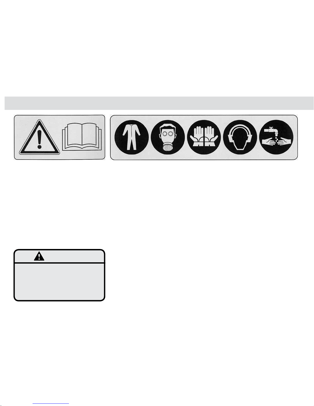
• Always read your sprayer operator’s manual
thoroughly before operating.
• Dispose of all chemical containers as per
instructions on label. Failure to do so could result
in contaminating the environment with chemicals.
• Inspect hose and hose connections daily. Always
wear rubber gloves when tightening connections.
Damaged, loose or worn hoses could result in
operator being exposed to toxic chemicals
which could result in serious illness or faulty
sprayer operation.
• Follow the chemical manufacturer’s precautions
before cleaning the sprayer. Exposure to
chemicals could result in serious illness or death.
• Always use the proper application rate. To assure
proper application rate calibrate sprayer
frequently. The wrong application rate of a
pesticide which is too high may expose the
operator and the environment to danger.
• Always wear gloves and wash the sprayer before
doing any disassembly repair work.
Chemical residues on the sprayer parts could
contaminate operator or service personnel
causing serious illness.
• Always relieve system pressure before doing any
work on the machine.
Disconnecting components while under pressure
will result in uncontrolled spray discharge which
may be hazardous to humans.
Failure to do so could cause operator to be
exposed to high pressure spray of chemical
resulting in serious injury or machine damage.
• Check the entire sprayer, prior to each use, for
any loose connections.
• Use only genuine Croplands parts for any
necessary replacement.
Home made parts may look the same but might
be dangerous in operation.
• Do not disconnect any hoses nozzles or filters
while sprayer is operating.
• Always clean the sprayer before doing any
repairs.
Accidents occur every year due to
careless use of farm machinery and farm
chemicals.
You can avoid these hazards by reading and
following the instructions in this operator's
manual and observing operating safety.
WARNING
Page 41

41
GP-OMCP12-B
Maintenance & Trouble Shooting Chapter 5
Trouble Shooting Pump Problems 38
Page 42

42
Maintenance & Trouble Shooting
GP-OMCP12-B
Trouble Shooting Pump Problems
PROBLEM
A. Failure to Prime
- motor operates, but no pump discharge.
B. Motor Fails to Turn On
C. Pump Fails to Turn Off
D. Low Flow and Pressure
E. Pulsating Flow
- Pump Cycling On and Off.
PROBABLE CAUSE
1) Restriction in intake or discharge line.
2) Air leak in intake line.
3) Punctured pump diaphragm.
4) Defective pump check valve.
5) Crack in pump housing.
6) Debris in filter or check valve.
1) Pump motor not electrically connected.
2) Fuse blown.
3) Loose wiring or connection.
4) Pressure switch failure.
5) Defective motor or rectifier.
6) Frozen cam-bearing.
1) Faulty pressure switch.
1) Blocked suction filter.
2) Air leak at pump intake.
3) Accumulation of debris inside pump & plumbing.
4) Worn pump bearing (excessive noise).
5) Punctured pump diaphragm.
6) Defective rectifier or motor.
7) Insufficient voltage to pump.
1) Restricted pump delivery.
2) Nozzle too small.
REMEDY
1) Open all line valves, check for “jammed” check
valve poppets & clean clogged lines.
2) Fix air leak in intake line.
3) Replace pump diaphragm.
4) Repair or replace pump check valve.
5) Replace pump housing.
6) Clean filter or check valve.
1) Make electrical connection.
2) Replace fuse.
3) Repair loose wiring or connection.
4) Replace pressure switch.
5) Replace motor or rectifier.
6) Repair or replace cam-bearing.
1) Replace faulty pressure switch.
1) Clean the suction filter.
2) Repair air leak on the pump intake.
3) Clean the inside of the pump and plumbing.
4) Replace pump bearing.
5) Replace pump diaphragm.
6) Replace rectifier or motor.
7) Correct voltage to pump.
1) Check discharge lines, fittings, valves & spray
nozzles for clogging or undersizing.
2) Ensure nozzle is correct size.
Page 43

43
GP-OMCP12-B
Assembly Drawings & Spare Parts Chapter 6
US30A 44
US60A &US100A 45
US100A/15 46
US200, 400 & 800 Models 47
UM70 Models 48
UW50 Models 49
Pumps 50
Accessories & Parts 51
Page 44
44
Drawings & Spare Parts
GP-OMCP12-B
7
6
10
5
8
9
11
3
4
1
2
13
12
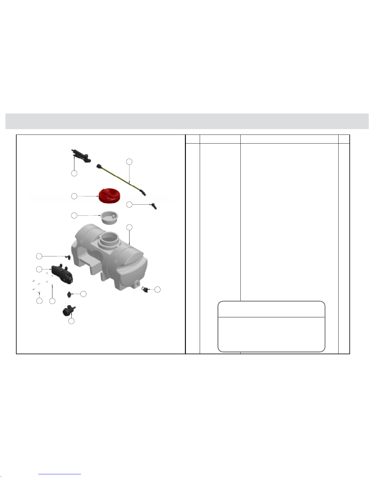
US30A
1 A2402021 NIPPLE 1/2” - 3/8” REDUCING 1
2 A309953 FILTER 1/2” BLACK PP 50MESH 1
3 BJHB038-90 ELBOW 3/8” NPT X 3/8” BARB 1
4 FL3501-506 PUMP TRIPLEX 7.6LPM 50PSI NO SWITCH 1
5 P30D-RAW TANK 30LT POLY UTEPAK 1
6 SW501-004 LID STRAINER 1
7 SW502-001C TANK LID ASSEMBLY RED 1
8 SW803-085 BRASS LANCE 52CM CURVED 1
9 SW803-262C ADJ PLASTIC NOZZLE & CAP NUT 1
10 SW808-073-C SHUT OFF VALVE F/ 3/8” ID HOSE 1
11 UP-416 BOAT PLUG 1
12 UP-501 S BEND HOSE EPDM BLACK 1
13 M6X16 M6 X 16 BOLT HT ZP 4
14 M6FWASHER M6 FLAT WASHER ZP 4
n/a HPW10 HOSE 6
n/a COBRAC18-19/8 CLAMP 2
n/a TR38HC CLAMP 3
n/a UP-119B SWITCH KIT 1
n/a GP-OMCP12-B MANUAL 1
Item Part Number US30A Parts Description Qty
This parts list is indicative of this model
sprayer.
For further parts information refer
www. croplands.com.au
NOTE
Page 45
45
Chapter 6
GP-OMCP12-B
US60A & US100A
1 A2402021 NIPPLE 1/2” - 3/8” REDUCING 1
2 A309953 FILTER 1/2” BLACK PP 50MESH 1
3 BJHB038-90 ELBOW 3/8” NPT X 3/8” BARB 1
4 FL3501-506 PUMP TRIPLEX 7.6LPM 50PSI NO SWITCH 1
5 P100D-RAW TANK 100LT POLY UTEPAK W/O FITTING 1
6 SW501-004 LID STRAINER 1
7 SW502-001C TANK LID ASSEMBLY RED 1
8 SW803-085 BRASS LANCE 52CM CURVED 1
9 SW803-262C ADJ PLASTIC NOZZLE & CAP NUT 1
10 SW808-073-C SHUT OFF VALVE F/ 3/8” ID HOSE 1
11 UP-416 BOAT PLUG 1
12 UP-501 S BEND HOSE EPDM BLACK 1
13 M6X16 M6 X 16 BOLT HT ZP 4
14 M6FWASHER M6 FLAT WASHER ZP 4
n/a COBRAC18-19/8 CLAMP 2
n/a TR38HC CLAMP 3
n/a UP-119B SWITCH KIT 1
n/a GP-OMCP12-B MANUAL 1
Item Part Number US100A Parts Description Qty
1 A2402021 NIPPLE 1/2” - 3/8” REDUCING 1
2 A309953 FILTER 1/2” BLACK PP 50MESH 1
3 BJHB038-90 ELBOW 3/8” NPT X 3/8” BARB 1
4 FL3501-506 PUMP TRIPLEX 7.6LPM 50PSI NO SWITCH 1
5 P60B-RAW TANK 60LT UTEPAK W/O FITTING 1
6 SW501-004 LID STRAINER 1
7 SW502-001C TANK LID ASSEMBLY RED 1
8 SW803-085 BRASS LANCE 52CM CURVED 1
9 SW803-262C ADJ PLASTIC NOZZLE & CAP NUT 1
10 SW808-073-C SHUT OFF VALVE F/ 3/8” ID HOSE 1
11 UP-416 BOAT PLUG 1
12 UP-501 S BEND HOSE EPDM BLACK 1
13 M6X16 M6 X 16 BOLT HT ZP 4
14 M6FWASHER M6 FLAT WASHER ZP 4
n/a HPW10 HOSE 6
n/a COBRAC18-19/8 CLAMP 2
n/a TR38HC CLAMP 3
n/a UP-119B SWITCH KIT 1
n/a GP-OMCP12-B MANUAL 1
Item Part Number US60 Parts Description Qty
These parts lists are indicative of these
model sprayers.
For further parts information refer
www. croplands.com.au
NOTE
Page 46

46
Drawings & Spare Parts
GP-OMCP12-B
US100A/15
1 A200020 FLY NUT 1/2” 12.5 MMD 1
2 A309953 FILTER 1/2” BLACK PP 50MESH 1
3 A908006 GAUGE 40MM 0-6 BAR 1
4 A9620050 PRV 1/2” FAST COUPLING 1
5 AG4000B FLAT SEAL 5/8” EPDM 1
6 B163.604.4 ELBOW 10MM 90DEG C/W 1/2” WING NUT 1
7 COBRAC18-19/8 COBRAC CLAMP 1/2” BLACK HOSE 2
8 CP8027-1-NYB CAP NYLON LONG 1
9 FL20381-000 KIT 1/2” THREAD STRAIGHT PAIR 1
10 FL3521-139 PUMP 12V 60PSI-15.1LT SANTO-VITON 1
11 P100D-RAW TANK 100LT POLY UTEPAK W/O FITTING 1
12 SW501-004 LID STRAINER 1
13 SW502-001C TANK LID ASSEMBLY RED 1
14 SW803-085 BRASS LANCE 52CM CURVED 1
15 SW803-262C ADJ PLASTIC NOZZLE & CAP NUT 1
16 SW808-073-C SHUT OFF VALVE F/ 3/8” ID HOSE 1
17 UP-416 BOAT PLUG 1
18 UP-501 S BEND HOSE EPDM BLACK 1
19 TR38HC HOSE CLAMP 10MM 3/8” WORM DRIVE 2
20 8121-NYB-540TD ELBOW SHANK NYLON 11/16”M-1/2” 1
21 8400-500-NYB CAP HOSE SHANK 1/2” HOSE NYLON 1
22 M6X16 M6 X 16 BOLT HT ZP 4
23 M6FWASHER M6 FLAT WASHER ZP 4
n/a TR12HC HOSE CLAMP 10MM 3/8” WORM DRIVE 2
n/a HPW10 HOSE 6
n/a HPW12 HOSE 1
n/a UP-119B SWITCH KIT 1
n/a GP-OMCP12-B MANUAL 1
Item Part Number US100A/15 Parts Description Qty
This parts list is indicative of this model
sprayer.
For further parts information refer
www. croplands.com.au
NOTE
Page 47

47
Chapter 6
GP-OMCP12-B
US200
P200B-RAW RAWTANK 1
FL3501-506 PUMP 1
A205020 BACKNUT 2
AG40002 FLATSEAL 1
COBRAC18-19/8 CLAMP 2
A2402021 REDNIPPLE 1
HPW10 HOSE 6
SW808-073C VALVE 1
SW803-262C JET 1
SW803-085 LANCE 1
HPW12 HOSE 1
COBRAC15/8 CLAMP 2
SW501-004 STRAINER 1
UP-169 PIPE 1
SW502-001C LID 1
UP-175 HOOK 4
UP-416 PLUG 1
B163.604.13 ELBOW 1
BJHB038-90 ELBOW 1
A309953 FILTER 1
UP-119B SWITCH KIT 1
GP-OMCP12-B MANUAL 1
Item Part Number US200 Parts Description Qty
This parts list is indicative of the 200, 400
& 800 sprayers.
For further parts information refer
www. croplands.com.au
NOTE
Page 48
48
Drawings & Spare Parts
GP-OMCP12-B
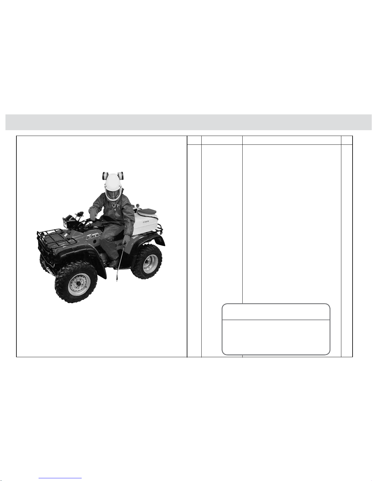
UM70
P70M-RAW RAWTANK 1
FL3501-506 PUMP 1
8121-NYB-540TD ELBOW 1
8400-406-NYB CAP 1
AG4000B FLATSEAL 1
COBRAC15/8 CLAMP 4
CP8027-NYB CAP 1
HPW10 HOSE 4
SW501-004 STRAINER 1
SW502-001C LID 1
SW803-085 LANCE 1
SW803-262C JET 1
SW808-073C VALVE 1
UP-108 BOXLID 1
UP-123 STRAP 1
8079-PP-50 STRAINER 1
BJHB038-90 ELBOW 2
UP-119B SWITCH KIT 1
GP-OMCP12-B MANUAL 1
Item Part Number US70 Parts Description Qty
This parts list is indicative of this model
sprayer.
For further parts information refer
www. croplands.com.au
NOTE
Page 49
49
Chapter 6
GP-OMCP12-B
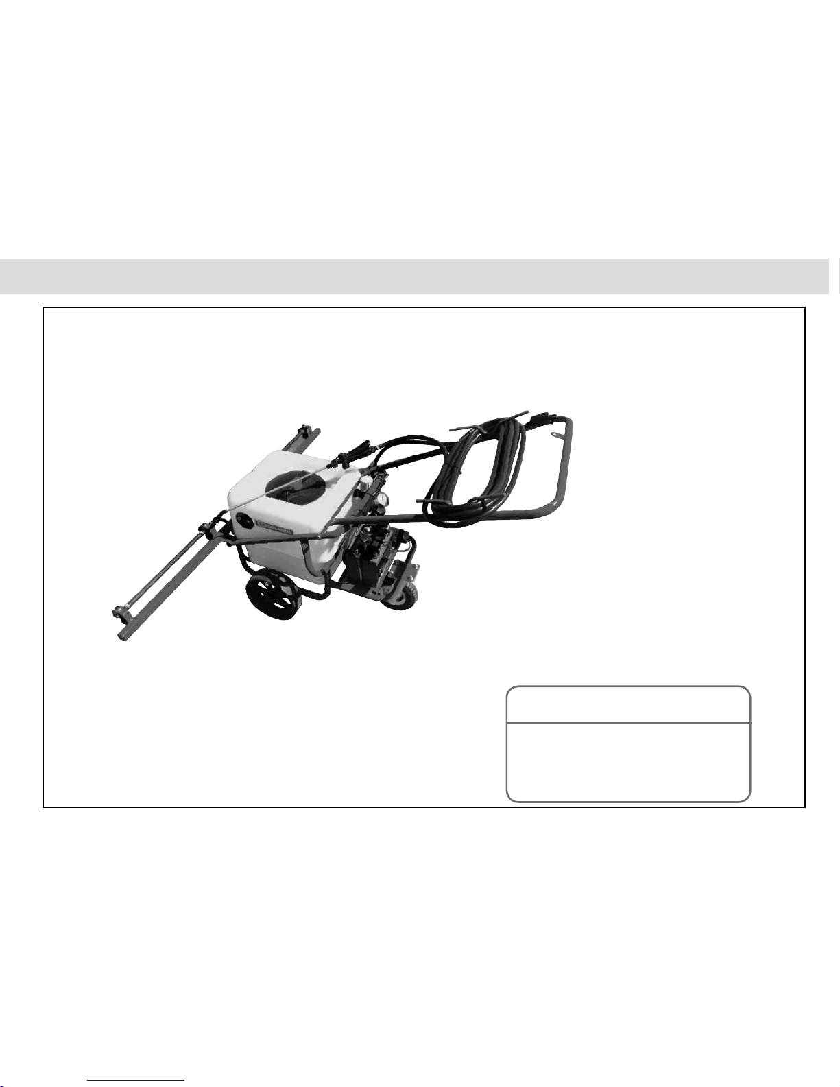
UW50/2B
For further parts information refer
www. croplands.com.au
NOTE
Page 50

50
Drawings & Spare Parts
GP-OMCP12-B
Pumps
For the latest pump drawings and
specifications see the Croplands Web
site and go to the Sprayer Components
section.
NOTE
Flojet FL3501-506
Flojet FL3521-139
Page 51

51
Chapter 6
GP-OMCP12-B
Hand Gun Accessories & Replacement Hose
D
C
B
A
E
F
G
KL J
I
H
MN
A SW219-117 Small spray guard, 22cm
B SW219-099 Large spray guard, 40cm
C SW-LANCE-P-ASSY Gun & lance (plastic) assembly c/w 10mm tail
D SW219-236C Telescopic lance 94cm c/w adjustable nozzle
E SW219-142C Spray lance 100cm (plastic) c/w adjustable nozzle
F SW219-143C Spray lance 150cm (plastic) c/w adjustable nozzle
G SW219-146C Spray lance 200cm (plastic) c/w adjustable nozzle
H SW219-282C 4-Nozzle boom 150cm (plastic)
I SW219-151C 3-Nozzle boom 150cm (plastic)
J SW219-138C 3-Nozzle boom 100cm (plastic)
K SW219-148C 2-Nozzle boom 75cm (plastic)
L SW219-140C 2-Nozzle boom 50cm (plastic)
M SW219-147C Double U Nozzle complete w/- caps
N SW803-262C Adjustable poly nozzle
Pic Order code Description
Left: Lance Hand Grip for all CropPak Sprayers
Part No: SW808-073C
Above: Swivel Nozzle for all CropPak Sprayers
Part No: SW803-262C (Plastic)
SW219-089C (Brass)
Above: Swissmex Lance, 52cm, brass. For all CropPak Sprayers
Part No: SW803-085
Page 52

Croplands Customer Service
Australia
Freecall: 1800 999 162
Freefax: 1800 623 778
www.croplands.com.au
Croplands Customer Service
New Zealand
Freecall: 1800 106 898
Freefax: 1800 117 711
www.croplands.co.nz
 Loading...