

Page 1

Digital Microhmmeter
Type DO7 PLUS
Operating Instructions
Bracken Hill, South West Industrial Estate,
Peterlee, Co. Durham SR8 2SW. England.
Tel: +44 (0)191-586 3511 Fax: +44 (0)191-586 0227
www.cropico.co.uk
[email protected]
Page 2

Operating Instructions
Digital Microhmmeter Type DO7 PLUS
Limited Warranty & Limitation of Liability
CROPICO guarantees this product for a period of 1 year. The period of warranty will
be effective at the day of delivery.
(c) Copyright 2009
All rights reserved. Nothing from this edition may be multiplied, or made public in
any form or manner, either electronically, mechanically, by photocopying, recording,
or in any manner, without prior written consent from CROPICO. This also applies to
accompanying drawings and diagrams.
Due to a policy of continuous development CROPICO reserves the right to alter the
equipment specification and description outlined in this publication without prior
notice and no part of this publication shall be deemed to be part of any contract for
the equipment unless specifically referred to as an inclusion within such contract.
Page 3
Operating Instructions
Digital Microhmmeter Type DO7 PLUS
Disposal of Old Product
This product has been designed and manufactured with high quality materials and
components that can be recycled and reused.
When the crossed out wheelie bin symbol is attached to a product it means the
product is covered by the European Directive 2002/96/EC.
Please familiarise yourself with the appropriate local separate collection system for
electrical and electronic products.
Please dispose of this product according to local regulations. Do not dispose of this
product along with normal waste material. The correct disposal of this product will
help prevent potential negative consequences for the environment and human
health.
User Note:
These Operating Instructions are intended for the use of Competent Personnel.
Page 4

Page No.
Section 1 – Instrument set-up and operation
Table of Contents
1. Introduction
1.1 Overview
1.2 Standard Features of the DO7PLUS
1.3 Definitions and Terminology
1.4 Specification
1.4.1 Measurement Accuracy
1.4.2 Temperature Compensation accuracy
1.4.3 Conditions of Use
1.4.4
1.4.5
Lead Resistance
DC Power Input
1.4.6 External Mains Power Unit
1.4.7 Battery Operation
1.4.8 Weight and Size
2. About the DO7PLUS
2.1 Safety Information
2.2
2.3
2.4
2.5
Unpacking the Instrument
Cleaning Instructions
Battery Pack Replacement
The Front Panel
3. Getting Started
3.1 Battery charger
3.2
About the Display Screen
4 Instrument Set-Up
4.1 Setting the DO7PLUS instrument configuration
4.2 Instrument SET UP table
4.3 Setting the DO7PLUS measurement configuration
4.4 Measurement configuration table
4.5 Setting the Range
4.6 Setting the measurement current
4.7 Zero Mode
4.8 Short cut keys
4.9 Menu options explained
4.9.1 Range
4.9.2 Current
4.9.3 Trigger
4.9.4 Limits
4.9.5 Data Log
4.9.6 Statistics
4.9.7 Graphics
4.9.8 Cooling Curve
4.9.9 Temperature Compensation
4.9.10 Filter
4.9.11 Settling
4.9.12 Cable Mode
4.9.13 Memories
5. Measuring with the DO7PLUS
5.1 Connecting to the DO7PLUS
5.2 Connecting to the resistance
5.3 Resistance Measurement
5.4 Measurement with temperature Compensation
5.5 Effects of lead resistance
6. Calibration
7. Firmware Update
8. RS232 Connection Diagram
9. Accessories
Section 2 Remote control Interface
Operating Instructions
Digital Microhmmeter Type DO7 PLUS
4
5
5
6
6
6
6
6
6
6
6
6
7
8
8
9
9
9
10
12
12
12
14
14
15
16
16
18
19
20
20
20
20
20
21
22
23
24
25
26
27
28
29
30
30
32
32
32
34
34
34
35
37
37
38
Page 5
1 INTRODUCTION
1.1 OVERVIEW
The DO7PLUS Microhmmeter is a high accuracy instrument designed for industrial and
laboratory resistance measurements. Its rugged case and robust construction ensures that
accurate and reliable measurements are delivered even under the harshest of environments.
The DO7PLUS is a true four wire measuring instrument eliminating the need to compensate
for lead resistance. The measured value is displayed in large characters with decimal point
and units kΩ, Ω, or mΩ. For maximum accuracy the measuring current may be automatically
reversed and the average of measurement displayed. For measurements on unstable
samples, a rolling average filter is available.
Resistance measurement accuracy is typically 0.05% (1 year specification) and the value may
be displayed with or without temperature compensation.
The front panel measurement connections are made via 4mm sockets located on the front
panel. The connection to a Pt100 temperature sensor is made with a Micro Buccaneer 400
series connector. For remote control both USB and RS232 interfaces are available which will
also enable the instrument firmware to be updated from a PC.
The included data-log function has the ability to display logged values in a table or graphical
format and notes may be added to each logged value. The DO7PLUS also has the facility to
automatically measure and calculate cooling curves displaying in both graphical and numeric
formats. This makes the DO7PLUS the ideal instrument for machine testing.
Hi/Lo limits are a standard feature
Operating Instructions
Digital Microhmmeter Type DO7 PLUS
4
Page 6

1.2 Standard features of the DO7PLUS Microhmmeter include:
x Graphical and Numerical display of electrical machine cooling curves
x Automatic temperature compensation
x Fast reading rate 2 measurements per second
x Measuring ranges from 6 mOhm to 6 kOhm
x Resolution 100 nOhm on 6mOhm range
x Up to 10 Amp measuring current
x Continuous measurement for inductive samples, single pulse measurement for fast
resistance tests
x Full test lead continuity testing
x Hi/Lo Limits with Red/Green front panel warning LEDS
x Switched current mode with automatic averaging ensures elimination of thermal emf
errors
x Multi lingual graphic LCD display for resistance measurement values as well as
configuration settings and statistical results.
x Advanced functions include data logging and statistical reporting with max/min, average
values, peak to peak value, and standard deviation. Full QWERTY keyboard for adding
notes to logged measurements
x RS232 and USB interfaces available for automated monitoring and controlling
applications
x Graphical display of logged values
x Full range of measurement accessories
1.3 Definitions and Terminology
n nano Ohm 0.000000001 Ohm
P: micrOhm 0.000001 Ohm
m: milliOhm 0.001 Ohm
k: kilOhm 1000 Ohm
Pt100 Platinum resistance sensor (100: at 0qC)
+U/-U Voltage connection
+I/-I Current connection
Four terminal Kelvin principle of measurement using 2 wires (+I and -I) to pass
measurement current through Rx and 2 wires (+U and -U) to measure the
voltage.
Kelvin clips Crocodile clips with isolated jaws, one side being the current I
connection, the other voltage U connection.
km Indicates cable length in Kilometres
m Indicates cable length in metres
Cooling Curve A method of determining the maximum temperature of an
electrical machine when running at full load
Operating Instructions
Digital Microhmmeter Type DO7 PLUS
5
Page 7
1.4 Specification
Prior to connecting this instrument always ensure that the circuit under test is electrically
isolated. Connecting this instrument to circuits which have not been isolated could lead to
a hazard.
1.4.1 Measurement accuracy
1.4.2 Temperature compensation accuracy
The accuracy of the temperature measurement is ±0.1% and uses a standard Pt100 sensor
(EN60751). This accuracy does not include errors due to the sensor itself. The temperature
measurement range is 0…+100°C and the default resistance measurement is referenced to
20°C when this option is used. Other reference temperatures may be selected by the user
over the range 0°C to +50°C
1.4.3 Conditions of use
The DO7PLUS is suitable for indoor and outdoor operation.
Maximum altitude: 2000m
Installation category: 50V CATIII
Pollution degree: 2 (according to IEC61010-1)
Storage temperature: -20°C…+50°C
Operation temperature: 0°C…+40°C
Relative humidity: up to 90% non condensing @ 31°C
IP Rating: IP 53 with lid open
IP 67 with lid closed
1.4.4 Lead resistance
The DO7PLUS will operate with long lead lengths providing the maximum lead resistance
does not exceed the following:
Current Leads Maximum resistance 60m each lead (120 m total)
Potential leads Maximum resistance 1keach lead (2k total)
1.4.5 DC Power Input
9–36VDC, 4A max
1.4.6 External Mains Power Unit
External mains psu 90V...253V, 47Hz...63Hz. Interchangeable leads International use (only
one lead supplied with instrument).
1.4.7 Battery Operation
Two internally fixed NiMH battery packs, with gas gauge circuits to monitor battery capacity.
An internal battery charger for each battery provides intelligent charging with automatic fast
and maintenance charging as required. The percentage of full charge for each battery is
indicated on the LCD display.
Range
Measuring
Current
Resolution FSV Accuracy at full rated current
6.0000m 10A
100nΩ
60mV
±(0.05%Rdg+0.01%FS)
60.000m 1 A
1μΩ
60mV
±(0.05%Rdg+0.01%FS)
600.00m 100mA
10μΩ
60mV
±(0.05%Rdg+0.01%FS)
6.0000Ω
10mA
100μΩ
60mV
±(0.05%Rdg+0.01%FS)
60.000Ω
1mA
1mΩ
60mV
±(0.05%Rdg+0.01%FS)
600.00Ω
100μA
10mΩ
60mV
±(0.05%Rdg+0.01%FS)
6.0000kΩ
100μA
100mΩ
600mV
±(0.05%Rdg+0.01%FS)
Operating Instructions
Digital Microhmmeter Type DO7 PLUS
6
Page 8

1.4.8 Weight and Size
Size: 358 x 269 x 155 mm (W D H)
Weight: 6.0 kg instrument only
Weight Packed: 8.5kg
Operating Instructions
Digital Microhmmeter Type DO7 PLUS
7
Page 9
2 About the DO7PLUS
This section introduces you to the features and functions of the DO7PLUS Microhmmeter
2.1 IMPORTANT SAFETY INFORMATION
If this instrument is used in a manner not specified in this document the protection provided
by this instrument may be impaired.
The instrument and all associated cables and leads must be checked for signs of damage
before the instrument is operated.
GENERAL
This instrument has been designed and tested to comply with the Electromagnetic
Compatibility Directive 89/336/EEC and Low Voltage Directive 93/68EEC in accordance with
EN 61010 -1 :2001 CatIII <50V relating to the safety requirements for electrical equipment for
measurement, control and laboratory use.
Before connecting the instrument to the mains supply, please ensure the following safety
precautions have been read and understood.
SAFETY SYMBOLS
The following symbols are used to describe important safety aspects of this instrument. These
symbols appear on the instrument and in the operation instructions.
Attention Symbol: Indicates a potentially hazardous condition exists and that it is necessary
for the operator to refer to the instruction manual to ensure the safe operation of this
instrument.
·
Caution - Risk of Electric Shock: Indicates hazardous voltages may be present.
Refer to the instruction manual for further safety information.
SUMMARY OF SAFETY PRECAUTIONS
The following general safety precautions must be observed while operating or servicing this
instrument. Failure to comply with these precautions may result in personnel injury or death.
LIVE CIRCUITS DANGER
Do not connect the power supply to, or operate this instrument with, the protective covers
removed. Component replacement and internal adjustments must be made by qualified
service personnel. Do not replace components with the power cable connected. Under certain
conditions, dangerous voltages may exist with the power cable removed. To avoid injuries
always disconnect power and discharge circuits before touching them.
DO NOT MODIFY THIS INSTRUMENT OR SUBSTITUTE PARTS
Because of the danger of introducing additional hazards, do not perform any unauthorised
modification or install substitute parts to the instrument. Only fuses with the rated current,
voltage and specified type should be used. Failure to do so may cause an electric shock or
fire hazard. Return the instrument to CROPICO for service and repair to ensure the safety
features are maintained.
DO NOT OPERATE IN EXPLOSIVE ENVIRONMENTS
The operation of this instrument in such an environment constitutes a safety hazard.
CERTIFICATION
CROPICO certifies that this product met its published specifications at the time of shipment
from our factory. All calibration measurements performed in the manufacture of this
instrument are traceable to National and International standards.
ASSISTANCE
For after sales support and product service assistance please contact CROPICO Customer
Support Group. Contact information is provided in the operation instruction manual.
Operating Instructions
Digital Microhmmeter Type DO7 PLUS
8
Page 10

2.2 Unpacking the instrument
When you unpack the DO7PLUS, check that the following items are present before starting to
use the unit:
• 1 x Printed Operating Instructions
• 1 x DO7PLUS Microhmmeter
• 1 x Power supply unit
• 1 x CDROM
• 1 x Calibration Certificate
• 1 x Standard lead pack LS05-P
• 1 x Standard USB lead
• 1 x RS232 lead
• 1 x Warranty Card
Please contact the CROPICO Customer Support Team immediately if any of these items are
missing or damaged.
Please note that we offer a wide selection of measuring leads and test fixtures, see section 9.
Please consult our sales staff to order the items most suited to your application.
2.3 Cleaning Instructions
The instrument should be cleaned using a soft cloth slightly dampened with water. No other
cleaning solvents should be used as these may damage the surface of the instrument.
2.4 Battery Pack Replacement
- Ensure all leads are removed from the front panel of the instrument.
- Ensure the instrument is turned off.
- Remove the 10 front panel screws and sealing washers and store in a safe place.
- Carefully lift out the front panel together with the main measuring unit.
- Remove both plugs from the battery pack by simply pulling them out.
- Place the unit safely to one side.
- Remove the 3 screws and sealing washers from the rear of the case and store in a safe
place.
- The battery pack can now be lifted out of the case.
- Place the new battery pack (Cropico part no 551A675) in the case and refit the rear panel
screws and sealing washers.
- Plug the main unit battery leads back into the battery.
These are colour coded – if the plugs are fitted into the wrong sockets no damage will be
done, but the instrument will not operate.
- Ensure the plugs are fully inserted
- Replace the main unit and secure with the front panel screws and sealing washers.
- Turn the power on. Three warning beeps will alert you to the LCD message that new
batteries have been fitted. Press ‘OK’ to continue.
- It is strongly recommended that the batteries be fully recharged. This will ensure the
internal “gas gauge” circuits are correctly calibrated.
- Do not open the battery pack, but return to Cropico for safe disposal.
Operating Instructions
Digital Microhmmeter Type DO7 PLUS
9
Page 11
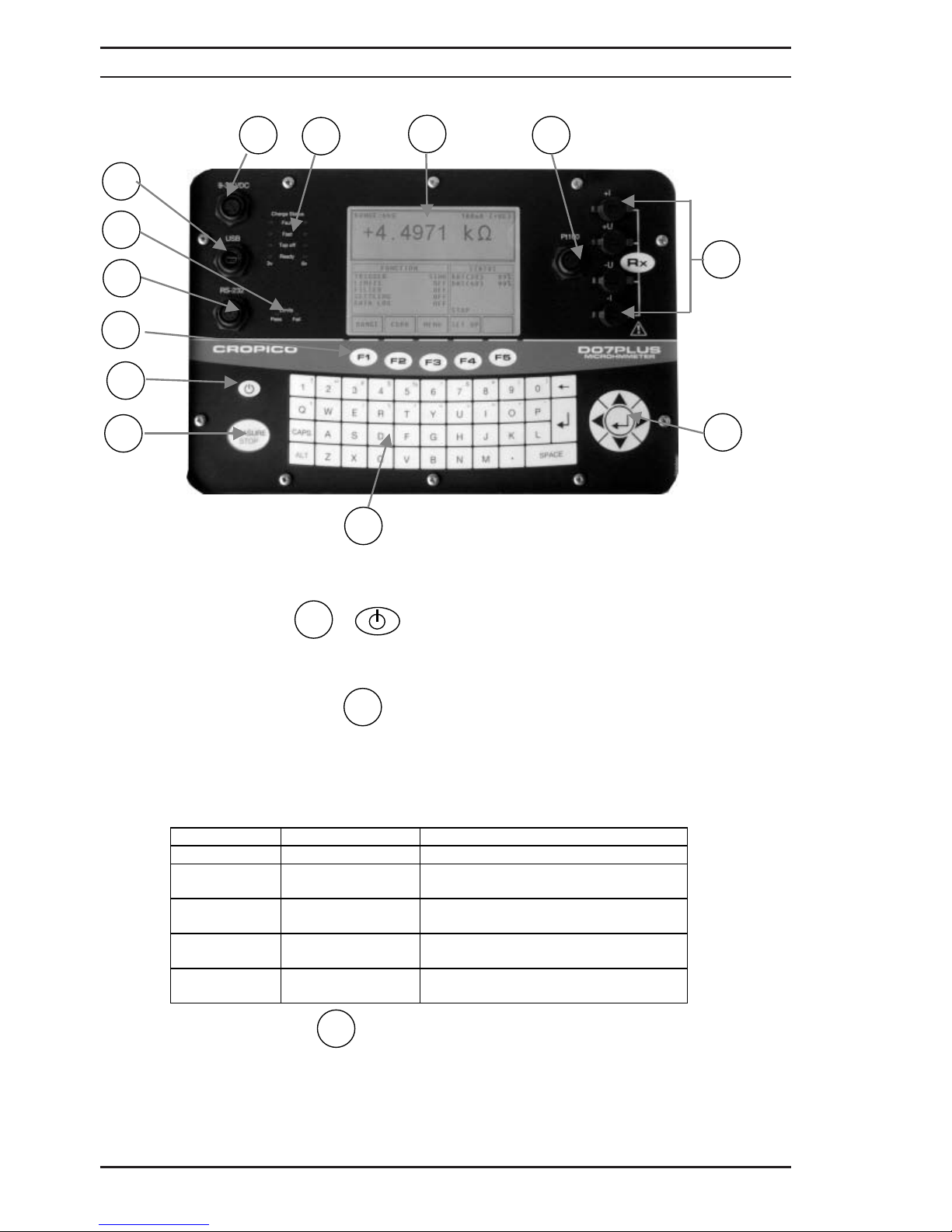
ON/OFF Switch
The On/Off switch switches the DO7PLUS on and off. The last measurement and function
setup is restored at power on. Auto switch-off to preserve battery life may be set between 10
and 60 minutes.
The Function Keypad F1...F5
All DO7PLUS measurements and programming facilities are accessed through the function
keypad (F1...F5). A brief description of these key functions are given in the following table.
For a detailed description of how to use the keys to configure and operate the DO7PLUS,
refer to section 4
Key Symbol Description Function
F1
RANGE Manual or automatic range can be set
F2
CURR
Current mode can be selected +I , -I,
Average, or Zero
F3
MENU
Displays all measurement
configuration details
F4
SET UP
Displays DO7PLUS configuration
including date, time, language etc.
F5
EXIT/ADD NOTE
If datalog is on & has one or more
entries allows test notes to be added
QWERTY Keypad
The full QWERTY keypad allows notes to be entered against logged measurement values
1
2
3
2.5. The Front Panel
1
2
3
4
5
6
7
8
9
10
11
12
13
Operating Instructions
Digital Microhmmeter Type DO7 PLUS
10
Page 12
MEASURE / STOP
Starts and stops the measurement in continuous measurement mode. Triggers measurement
in single measurement mode.
Navigation and enter Key
Moves display cursor and confirms selection.
LIMITS Pass / Fail LEDS
When limit function is set the green led lights to confirm measurement is within limits. Red led
lights if the measurement is outside the set limits.
Power input socket
For connection of power supply or optional car lead to charge batteries.
Charger status Indicator
LEDS indicate state of battery charging.
USB Socket
For connection of USB cable enabling full computer control.
RS232 Socket
For connection of RS232 cable enabling full computer control.
Pt100 input Socket
For connection of Pt100 temperature sensor.
Measurement input sockets
Prior to connecting this instrument always ensure that the circuit under test is electrically
isolated. Connecting this instrument to circuits which have not been isolated could lead to
a hazard.
Four 4mm safety sockets for connection of measurement leads.
Measurement Display
Displays measured values and information screens.
4
5
6
7
8
9
10
11
12
13
Operating Instructions
Digital Microhmmeter Type DO7 PLUS
11
Page 13
3 GETTING STARTED
3.1 Battery Charger
The DO7PLUS is powered by two internal NiMH batteries. A 6V battery supplies power to the
display and operating circuits, and a 3V battery supplies the measuring current. Once the
power supply is connected to the socket (7) charging is automatic and regulated to ensure the
batteries are kept in the best possible condition. Charge status LEDS (8) show the charging
status for each battery independently. The green READY LEDS will light when batteries are
sufficiently charged for a measurement. The TOP-OFF LEDS indicate a low maintenance
current and the FAST LEDS indicate the batteries are being charged with maximum current. If
a fault condition occurs then the FAULT LEDS will illuminate. Should this occur the instrument
should be taken out service and returned to a Cropico service centre for investigation and
rectification. The power supply should not be opened, dismantled or mechanically interfered
with.
In addition to the mains power supply provided with the DO7PLUS, a charging lead with car
style plug is available as an option enabling the DO7PLUS to be charged with 12 or 24 Volts
DC whilst away from base.
Note: To ensure correct charging operation, the DO7Plus must be switched off during battery
charging.
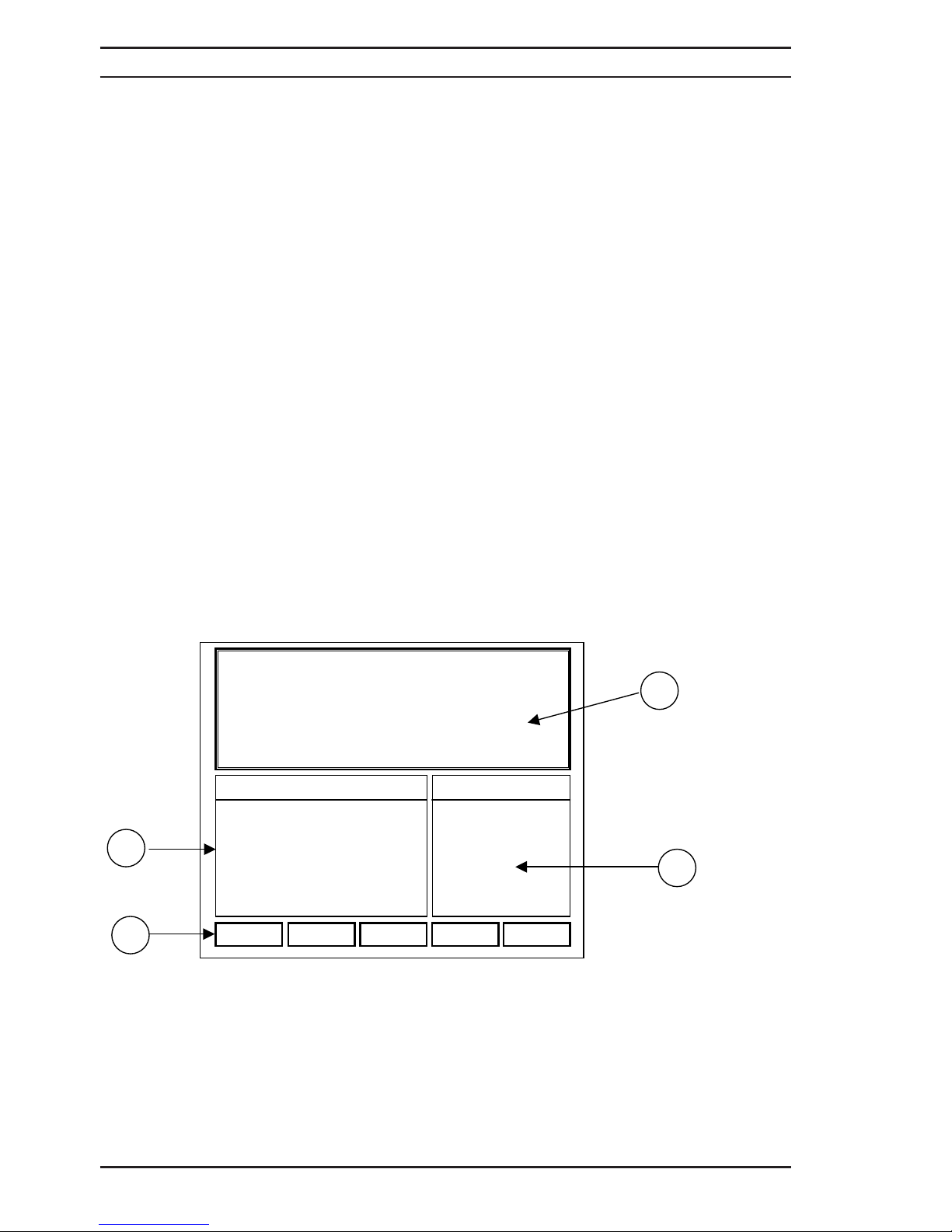
3.2 About the DO7PLUS Display screen
The display is a graphic LCD panel with backlight giving good readability and contrast. Full
measurement information is displayed with the measured value in large bold text. The
measurement set-up parameters are shown in a clear and unambiguous way.
Figure 3.2.1 - Example of Resistance Measurement Mode
RANGE: 6k 100μA ( +VE )
+5.0589 k
FUNCTION STATUS
TRIGGER
LIMITS
FILTER
SETTLING
DATA LOG
SING
OFF
OFF
OFF
OFF
BATT (3V)
BATT (6V)
98%
92%
STOP
RANGE
CURR MENU SET UP
A
C
D
B
Operating Instructions
Digital Microhmmeter Type DO7 PLUS
12
Page 14

Measurement Window
Displays:
x Measured value with sign and units.
x The selected measurement range, current and measurement mode.
x RX+ and RX- value when in average mode.
x Compensated value and measured Rx value plus temperature when in
temperature compensation mode.
Function Window
Displays :
x Trigger mode selected
x Limits status ( OFF, <<Hi>>, <<Lo>> , >>OK<< )
x Filter settings
x Settling settings
x Data Log Status
x Timer (if active)
Status Window
Displays :
x Battery charge state in % of full charge
x Memory number
x Remote status
x Measure / Stop condition
Function Soft Keys
x Five soft keys give access to setup menus
A
B
C
D
Operating Instructions
Digital Microhmmeter Type DO7 PLUS
13
Page 15
4 Instrument Set-up
4.1 Setting the DO7PLUS instrument configuration
These are the instrument housekeeping settings and once your preferences are selected and
stored they will seldom need to be changed.
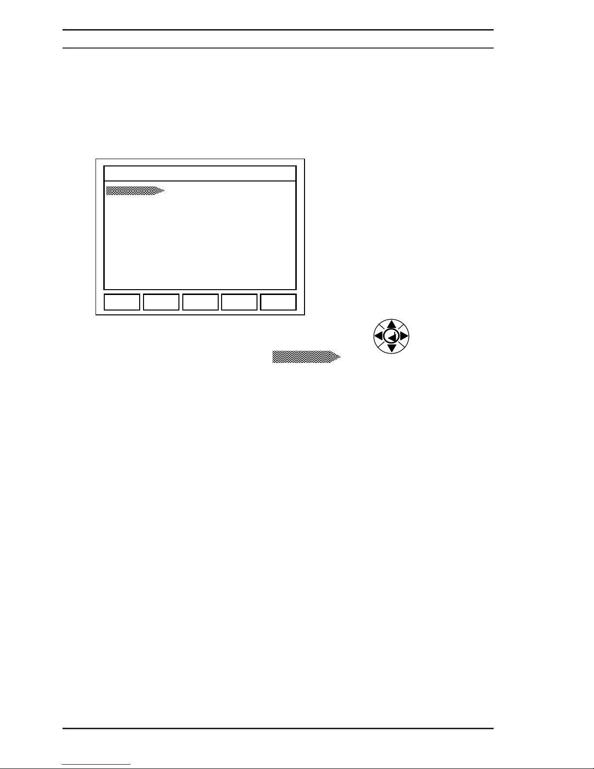
To select and change a setting proceed as follows:PRESS F4 (SETUP) and the following screen will display
HINT: To navigate around the screen use the navigation arrows
Where an item is highlighted with an arrow
this indicates that additional options are available for that parameter and the right
navigation arrow should be pressed to reveal those options.
The table Fig. 4.2.1 below shows the options available together with a brief description
BACKLIGHT
SETUP MENU
EXIT
BACKLIGHT 60 SECS
A
UTO OFF 15 MIN
KEY BEEP OFF
BEEPER ON
DATE FORMAT DD/MM/YY
DATE 29/04/08
TIME 16:23
LANG ENG
LINE FREQ 50HZ
TEMP UNIT GC
BACKLIGHT
Operating Instructions
Digital Microhmmeter Type DO7 PLUS
14
Page 16
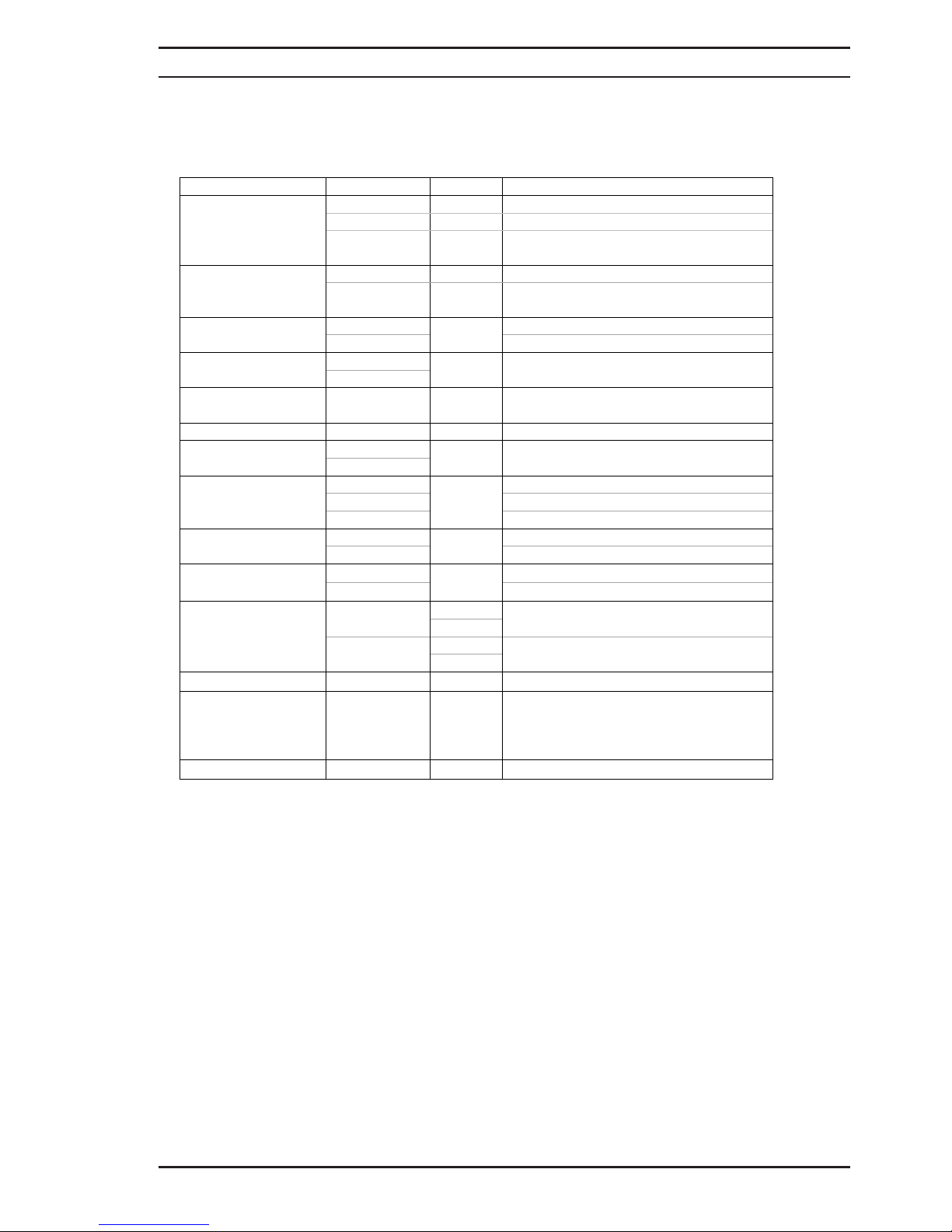
4.2 F4 SETUP
To enter the configuration menu PRESS F4 (SETUP) the following can then be set.
Fig4.2.1
FUNCTION OPTIONS Description
OFF Switches backlight OFF
ON Switches Backlight ON
BACKLIGHT
AUTO
10–60
seconds
Automatically switches off after 10...60
seconds selectable
OFF Disables Auto-OFF
AUTO OFF
ON
10-60
minutes
Automatically switches off after 10...60
minutes selectable
OFF Switches beep on key press OFF
KEY BEEP
ON Switches beep on key press ON
OFF
BEEPER
ON
Switches warning Beep ON or OFF
DD/MM/YY
DATE FORMAT
MM/DD/YY
Displayed date format may be selected
DATE 28/04/08 Correct date may be entered
11:37
TIME
(HH:MM)
Correct time may be entered
ENG Selects English Language
FRA Selects French Language
LANGUAGE
DEU Selects German Language
50Hz Selects 50Hz line frequency
LINE FREQUENCY
60Hz Selects 60Hz line frequency
qC Selects qC temperatures for display TEMPERATURE
UNIT
qF Selects qF temperature for display
9600
BAUD RATE
19200
Selects interface baud rate
OFF
REMOTE
TALK ONLY
ON
Switches Talk Only mode OFF or ON
VERSION Ver 1.0 Version of firmware installed
PASSCODE
Enables Passcode to be changed,
Passcode is required for calibration
menu and to update firmware.
Factory set Passcode = 9252
CAL See section 6 for Calibration Mode
Operating Instructions
Digital Microhmmeter Type DO7 PLUS
15
Page 17
4.3 Setting the DO7PLUS Measurement Configuration
To set or change a measurement configuration PRESS F3 (MENU) and the following screen
will display
HINT: To navigate around the screen use the
navigation arrows
Where an item is highlighted with an arrow
this indicates that options are available for that parameter and the right navigation
arrow should be pressed to reveal those options.
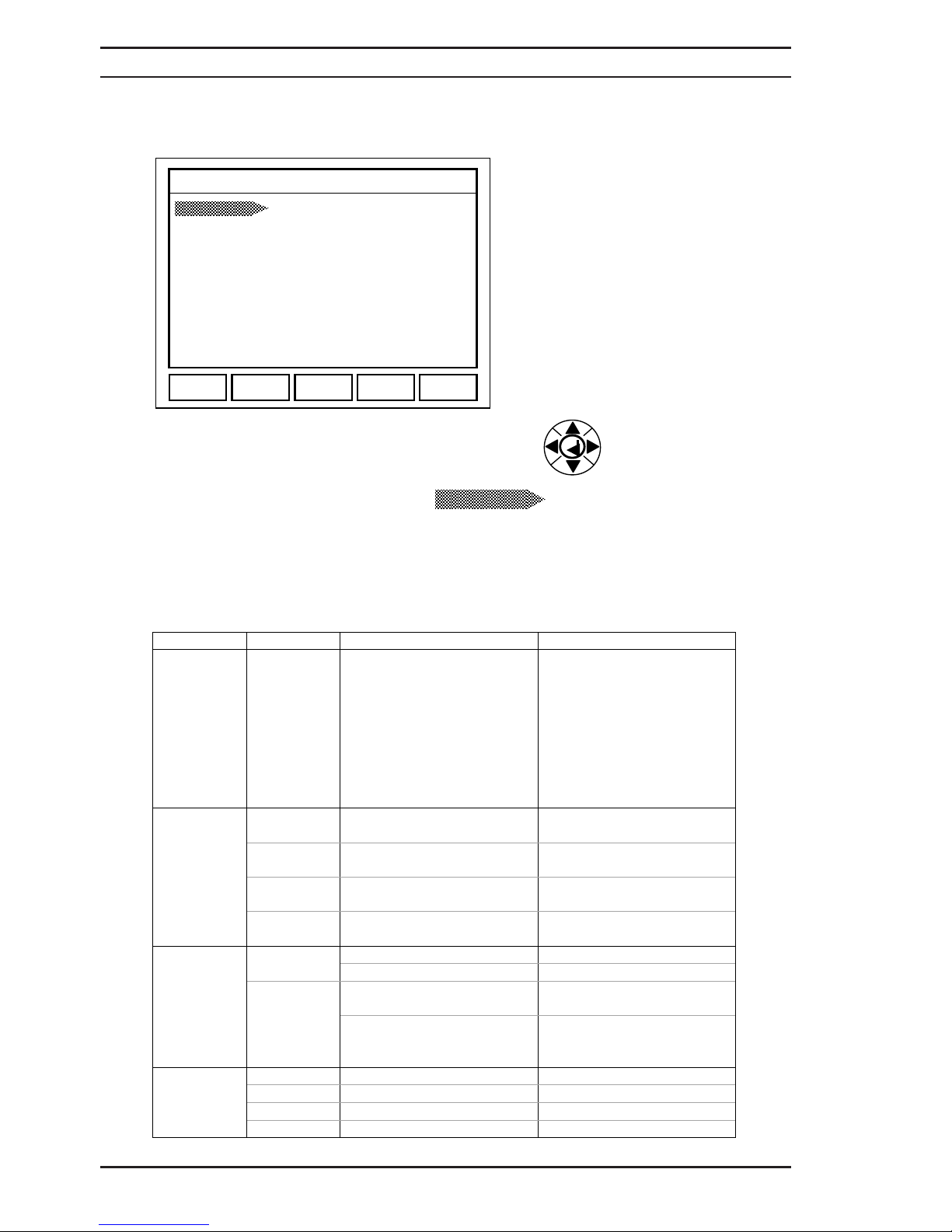
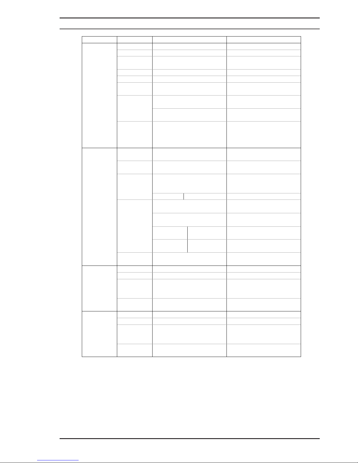
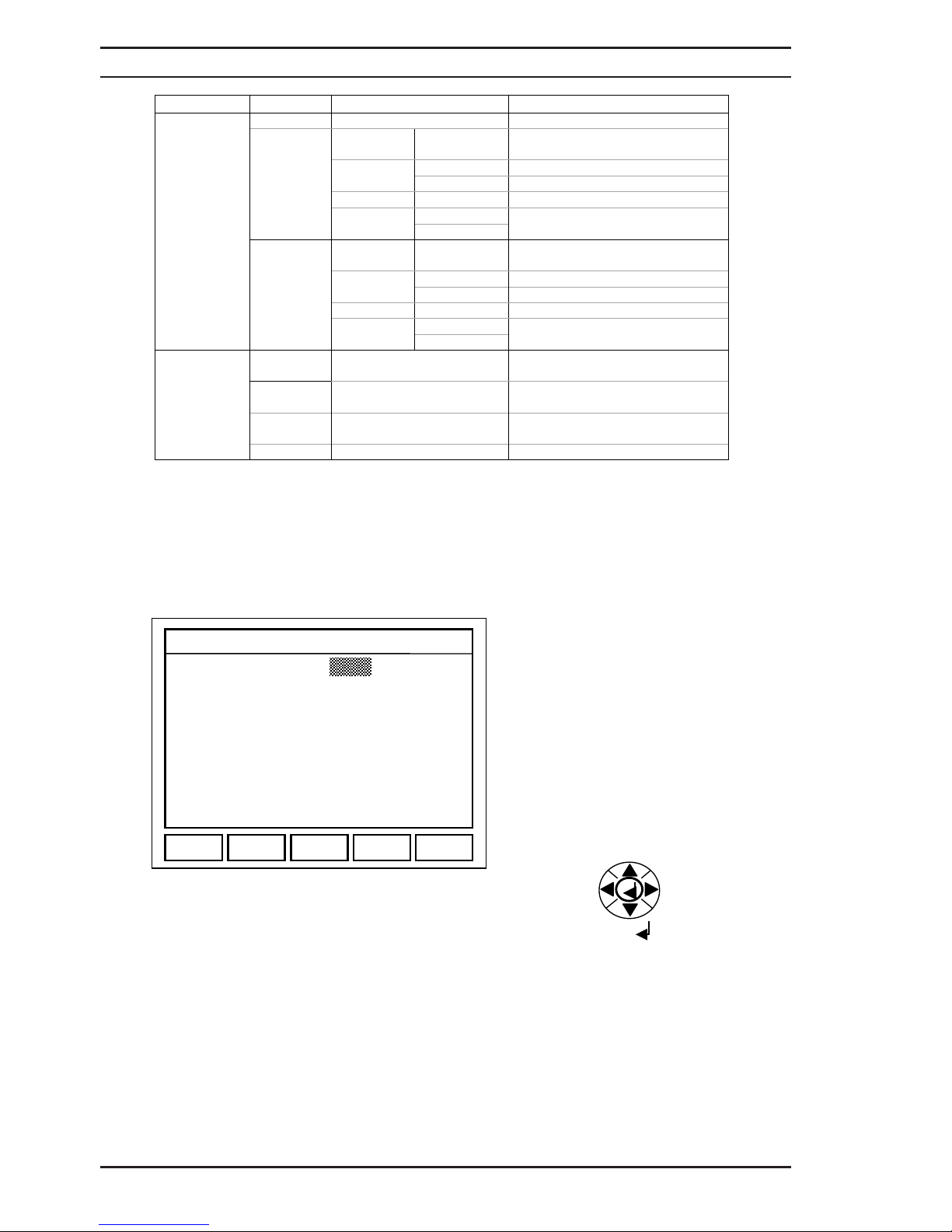
The table Fig. 4.4.1 below shows the options available together with a brief description
4.4 F3 MENU (Measurement Configuration)
To enter the measurement configuration menu PRESS F3 (MENU) the following can then be set.
Fig 4.4.1
FUNCTION OPTIONS OPTIONS 2 DESCRIPTION
6K
600
60
6
600m
60m
6m
AUTO1
RANGE
AUTO2
Selects the range required
or automatic range
selection. AUTO1 selects
automatic ranging starting
with the 6k range. AUTO2
selects automatic ranging
starting from last selected
range
+I
Selects measurement
current in positive direction
-I
Selects measurement
current in negative direction
AVERAGE
Measures with +I then with
–I and displays average
CURRENT
MODE
ZERO
Measures emf in circuit and
deducts from measurement
SINGLE Single pulse measurement
MEAS
CONTINUOUS Continuous measurement
MAN
Manual trigger with
measure key
TRIGGER
AUTO
AUTO
Automatically triggers
measurement when test
leads are connected
OFF Switches Limits OFF
ON Switches Limits ON
MAX MAX LIMIT = Set Limit Max Value
LIMITS
MIN MIN LIMIT = Set Limit MIN Value
INSTRUMENT MENU
EXIT
BACKLIGHT
6K
CURRENT AVERAGE
TRIGGER SING/AUTO
LIMITS OFF
DATA LOG ON
TEMP COMP OFF
FILTER ON
SETTLING OFF
CABLE MODE OFF
MEMORIES OFF
RANGE
RANGE
Operating Instructions
Digital Microhmmeter Type DO7 PLUS
16
Page 18
FUNCTION OPTIONS OPTIONS 2 DESCRIPTION
OFF Switches Data Log OFF
ON Switches Data Log ON
REVIEW
Displays logged
measurements
DELETE DELETE DATA LOG Deletes all logged values
No RDGS Number of readings = Enter number of readings
TIMER Timer Interval =
Enter time interval between
logged readings
FROM
Enter log starting number
for stats calculation
STATS
TO
Enter log ending number
for stats calculation
MODE
DATD RANGE
STATS
DATA LOG
GRAPHICS
EXIT
See section 5.10.7 for
details of Graphics
OFF
Switches temperature
compensation OFF
ON
Switches temperature
compensation ON
Pt100
Selects temperature
measurement with Pt100
external probe
TEMP
MANUAL Temperature = Enter temperature manually
Cu (3930)
Temperature coefficient of
copper 3930ppm/qC
Al (4030)
Temperature coefficient of
Aluminium 4030ppm/qC
USER 1 Coefficient =
Enter temperature
coefficient
COEFF
USER 2 Coefficient =
Enter temperature
coefficient
TEMP
COMP
REF TEMP Reference temperature =
Enter temperature 0 to
50qC
OFF Switches FILTER OFF
ON Switches FILTER ON
No RDGS Number of readings =
Enter number of readings
between 2 and 50 to be
averaged
FILTER
RESET
Resets filter average to
zero
OFF Switches SETTLING OFF
ON Switches SETTLING ON
No RDGS Number of readings =
Enter number of readings
to be within settling limit
2 to 999
SETTLING
LIMIT Settling Limit =
Enter number of digits
change permitted 1 to 999
Operating Instructions
Digital Microhmmeter Type DO7 PLUS
17
Page 19
FUNCTION OPTIONS OPTION 2 DESCRIPTION
OFF Switches cable mode OFF
No
CABLES
Cables =
Enter number of cables to be
measured
Series Cables connected in series
CONN
Parallel Cables connected in parallel
LENGTH Length = Enter length of cable
METRE
LENGTH
UNIT
KILOMETRE
Select units required
No
CABLES
Cables =
Enter number of cables to be
measured
Series Cables connected in series
CONN
Parallel Cables connected in parallel
RES/m Resistance = Enter resistance of cable in /m
METRE
CABLE
MODE
LENGTH
UNIT
KILOMETRE
Select units required
F2
RECALL
Select Memory Number
Recalls all settings for memory
number recalled
F3 STORE Select Memory Number
Saves all settings in memory
number selected
F4 CLEAR Select Memory Number
Deletes all stored data in memory
number selected
MEMORIES
F5 LIST Lists all memory status
4.5 Setting the Instrument Range
Some of the measurement functions need to be changed more frequently than others and
these may accessed directly, to change the RANGE settings PRESS F1 and the following
screen will display.
F1 RANGE
The F1 function key will take you straight to the range set-up menu
HINT: To navigate around the screen use the navigation arrows
To select the highlighted range PRESS OK (F5) or the carriage return key
Pressing the left arrow will return you to the measurement screen without
selecting the new highlighted range.
Pressing F1 (ESC) escapes the range menu and returns to the measurement
screen without updating the range.
AUTO RANGE
Two modes of auto-range may be selected AUTO1 where the DO7PLUS will start at the
highest range and work down. AUTO2 selects the last range used and then ranges up or
down.
HINT: The AUTO2 will often find the correct range the fastest
AUTO1 will always start with the highest range which uses the smallest measuring current
and will avoid overheating temperature sensitive devices.
INSTRUMENT MENU
RANGE:
600
60
6
600m
60m
6m
AUTO1
AUTO2
6K
ESC
OK
Operating Instructions
Digital Microhmmeter Type DO7 PLUS
18
Page 20
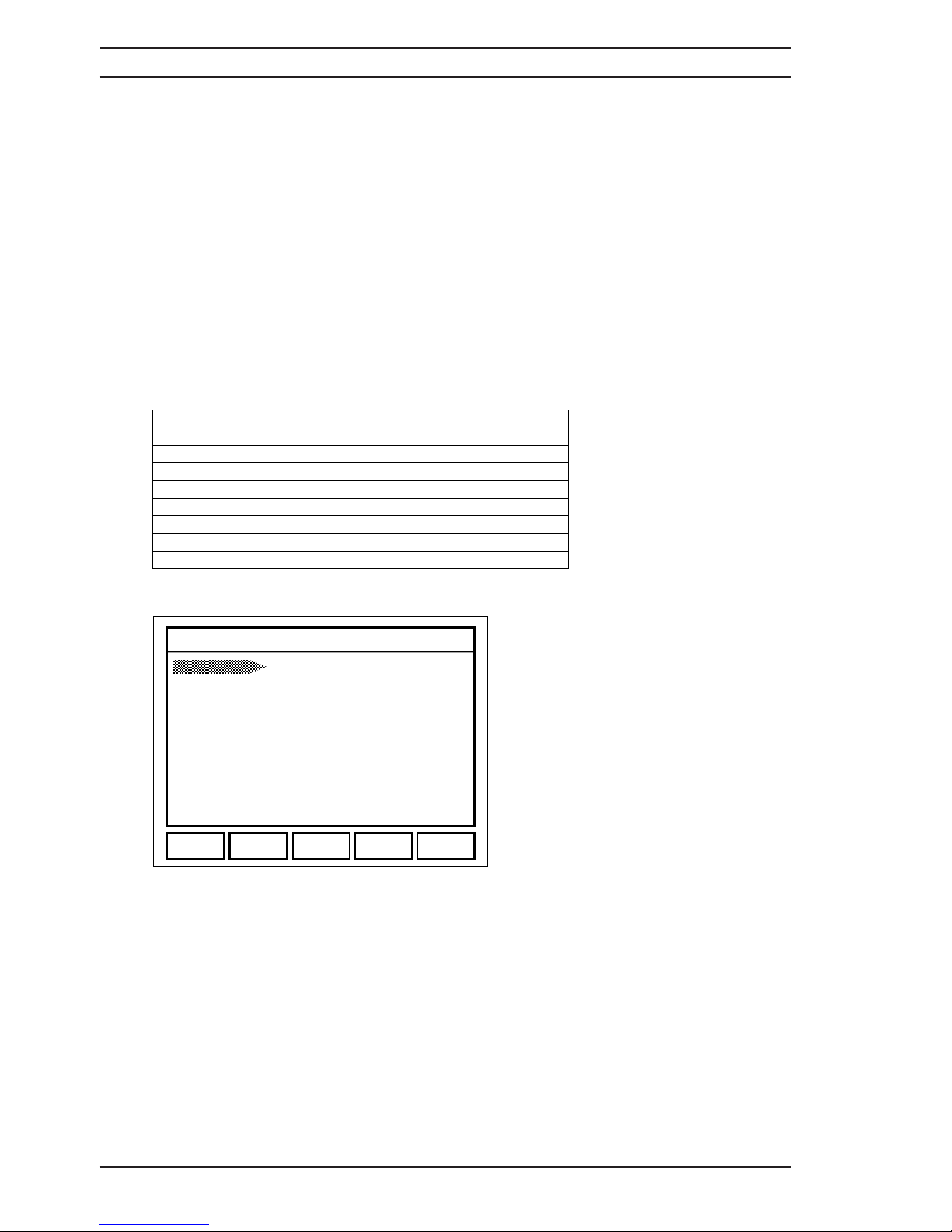
Do NOT use Auto-range when measuring inductive devices e.g. motors and transformers.
Fig 4.5.1 Measuring ranges with maximum current and resolution
Range Measuring Current Resolution
6.0000m 10A
100nΩ
60.000m 1 A
1μΩ
600.00m 100mA
10μΩ
6.0000Ω
10mA
100μΩ
60.000Ω
1mA
1mΩ
600.00Ω
100μA
10mΩ
6.0000kΩ
100μA
100mΩ
4.6 Setting the Measurement Current Mode
F2 Current
The F2 function key will take you directly to the measurement current set-up menu
HINT: To navigate around the screen use the navigation arrows
To select the highlighted mode PRESS OK (F5) or the carriage return key
Pressing the left arrow will return you to the measurement screen without
selecting the new highlighted range.
Pressing F1 (ESC) escapes the range menu and returns to the measurement
screen without updating the range.
+ I The measurement current flows in the positive direction
- I The measurement current flows in the negative direction
AVERAGE The measurement is made with +I current then a second measurement with
-I current, and the average value of the two measurements is displayed. The
average measurement will eliminate the effects of thermal emf and is
recommended for all resistive measurements.
WARNING: The AVERAGE mode should NOT be used when measuring inductive samples
such as transformers or motor windings. In these cases use the +I mode which will give
continuous and uninterrupted measurement current, ensuring the inductance is fully charged
and the correct reading displayed.
INSTRUMENT MENU
CURRENT: +I
-I
ZERO MODE
ESC
OK
AVERAGE
Operating Instructions
Digital Microhmmeter Type DO7 PLUS
19
Page 21
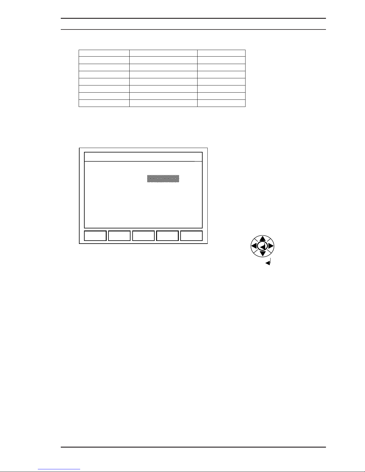
4.7 ZERO MODE
The DO7PLUS uses a four-wire internal zero measurement. The current terminals are
internally shorted together and the first measurement made. The potential terminals will
measure any emf in the circuit and this value is stored. A second measurement is then
performed with the current and potential leads connected in the normal way. The stored emf
is deducted from this measurement and the resulting value displayed. This measurement
mode eliminates errors due to emf flowing in the circuit.
x In single trigger mode the DO7PLUS will perform a zero measurement for each
measurement triggered.
x In continuous measurement mode one zero measurement is made followed by
continuous normal measurements until the measurement is stopped. If the
measurement is restarted, then another zero measurement is made followed by
continuous measurements.
If a range change is made, either manually or by the auto-range function, or a measurement
error occurs, then a new zero measurement will be performed.
4.8 Short cut keys enable quick access to menus
Short cut Key Function Menu
ALT + T = TRIGGER
ALT + L = LIMITS
ALT + F = FILTER
ALT + S = SETTLING
ALT + D = DATA LOG
ALT + C = TEMPERATURE COMPENSATION
ALT + G = GRAPHICS
ALT + M = MEMORIES
4.9 F3 MENU OPTIONS EXPLAINED
4.9.1 RANGE:
See Range selection 4.5
4.9.2 CURRENT:
See Current selection section 4.6
INSTRUMENT MENU
EXIT
BACKLIGHT 6K
CURRENT AVERAGE
TRIGGER SING/AUTO
LIMITS OFF
DATA LOG ON
TEMP COMP OFF
FILTER ON
SETTLING OFF
CABLE MODE OFF
MEMORIES OFF
RANGE
Operating Instructions
Digital Microhmmeter Type DO7 PLUS
20
Page 22
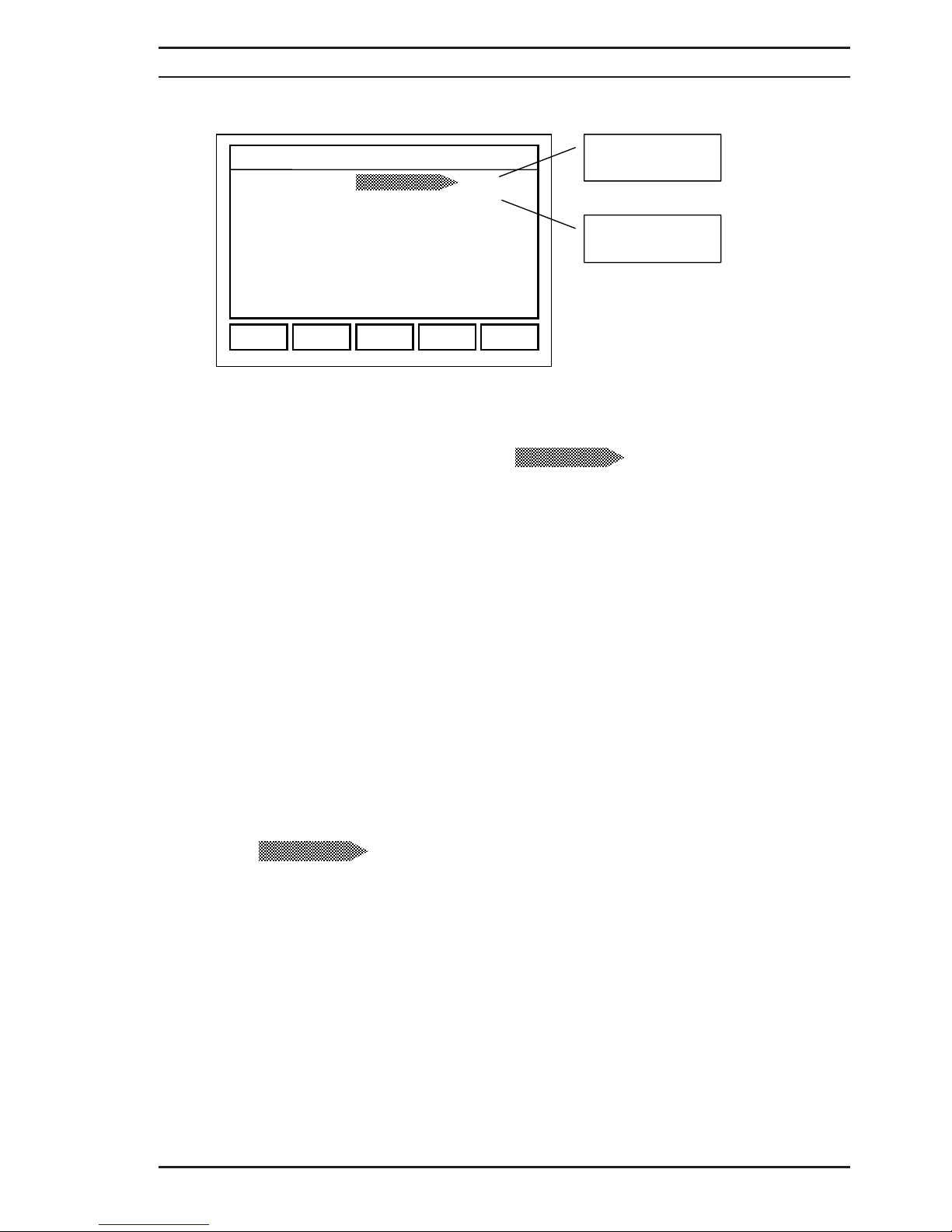
4.9.3 TRIGGER:
Fig. 4.9.1
The DO7PLUS measurement can be triggered in several ways.
Setting Single or Continuous Measurement Mode
The DO7PLUS may be set to continuous or single measurement mode.
When in the TRIGGER menu window select Fig: 4.9.1 press the right
navigation arrow key and then select either SINGLE or CONTINUOUS. Once this mode is set
it will apply to both the manual and automatic trigger modes. Press OK (F5) to accept choice.
Single Measurement Mode
When this mode is set, a single pulse measurement will be made and the value held on the
display.
HINT: This mode is particularly useful when you want to avoid the self heating effect of the
measurement current.
WARNING:
this trigger mode is NOT suitable for measuring inductive samples such as
transformers or motor windings. For these applications a continuous measurement current
should be used.
Continuous Measurement Mode
If continuous measurement is selected then the measurement will start when the
MEASURE/STOP button is pressed. The measurement current will flow continuously in the +I
and –I current modes and will be continuously switched in the AVERAGE current mode.
Continuous measurements will be taken and displayed, to Stop the measurement press the
MEASURE/STOP key and the measurement current will be disconnected and the last
measured value held on the display.
Setting Manual or Automatic Measurement Mode
To set the measurement for manual or automatic triggering select Auto when in the trigger
menu press the right hand navigation arrow key and then select either
MAN for Manual triggering or AUTO for automatic triggering. Press OK (F5) to accept choice.
Manual Measurement Mode
In this mode all measurements are started and stopped manually using the MEASURE/STOP
key. When the measurement is stopped the measuring current is disconnected and the last
measured value held on the display.
INSTRUMENT MENU
TRIGGER:
SING
A
UTO
MEAS
A
UTO
ESC
OK
SINGLE
CONTINUOUS
MAN
AUTO
MEAS
AUTO
Operating Instructions
Digital Microhmmeter Type DO7 PLUS
21
Page 23
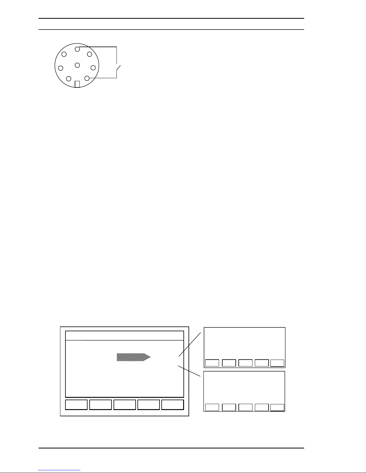
Remote manual triggering
As an alternative to pressing the MEASURE/STOP key to trigger, a measurement, the remote
start facility can be used. Connect a switch between pins 1 and 5 of the RS232 input
connector and close the contacts to start a measurement.
HINT: Connecting a footswitch or measuring probe with an external start button permits single
person operation. Values can be stored in the datalog for future analysis.
Automatic Measurement Mode
In this trigger mode the system allows a measurement to be taken simply by connecting the
measurement leads to the test piece. The measurement will not be triggered if the display is
in the menu mode.
Automatic measurement in single mode:
In most modes (Simple, Limits, Filter, Settling, Autorange, Temp Comp, any current mode,
and normal Datalog), Auto trigger causes one complete measurement to be made and held
on the display.
When in Datalog Timer mode:
Auto trigger starts to take the prescribed number of measurements at the selected timer
intervals.
HINT: Removing and replacing the measurement leads will have no further effect, other than
causing an error indication.
Automatic measurement in continuous mode:
In most modes (Simple, Limits, Filter, Settling, Autorange, Temp Comp, any current mode,
and normal Datalog):
Auto trigger starts continuous measurements.
HINT: Removing and replacing the measurement leads will have no further effect, other than
causing an error indication.
Automatic measurement when in Datalog Timer mode:
Auto trigger starts to take the prescribed number of measurements at the selected timer
intervals, maintaining the current at all times.
Hint: removing and replacing the measurement leads will have no further effect, other than
causing an error indication.
4.9.4
LIMITS
DO7PLUS RS-232 CONNECTION SOCKET
Pins numbered as viewed from rear of plug (cable side)
x PIN 1 ... REMOTE START
x PIN 5 ...GROUND
1
2
3
4
5
6
7
8
INSTRUMENT MENU
LIMITS:
6.0000 k
5.0000 k
OFFS
ON
MAX
MIN
ESC
OK
MAX
MAX LIMITS: k
(0 -- 6k)
ESC
UNIT CLEAR
OK
MIN LIMITS: k
(0 -- 6k)
ESC UNIT CLEAR OK
Operating Instructions
Digital Microhmmeter Type DO7 PLUS
22
Page 24
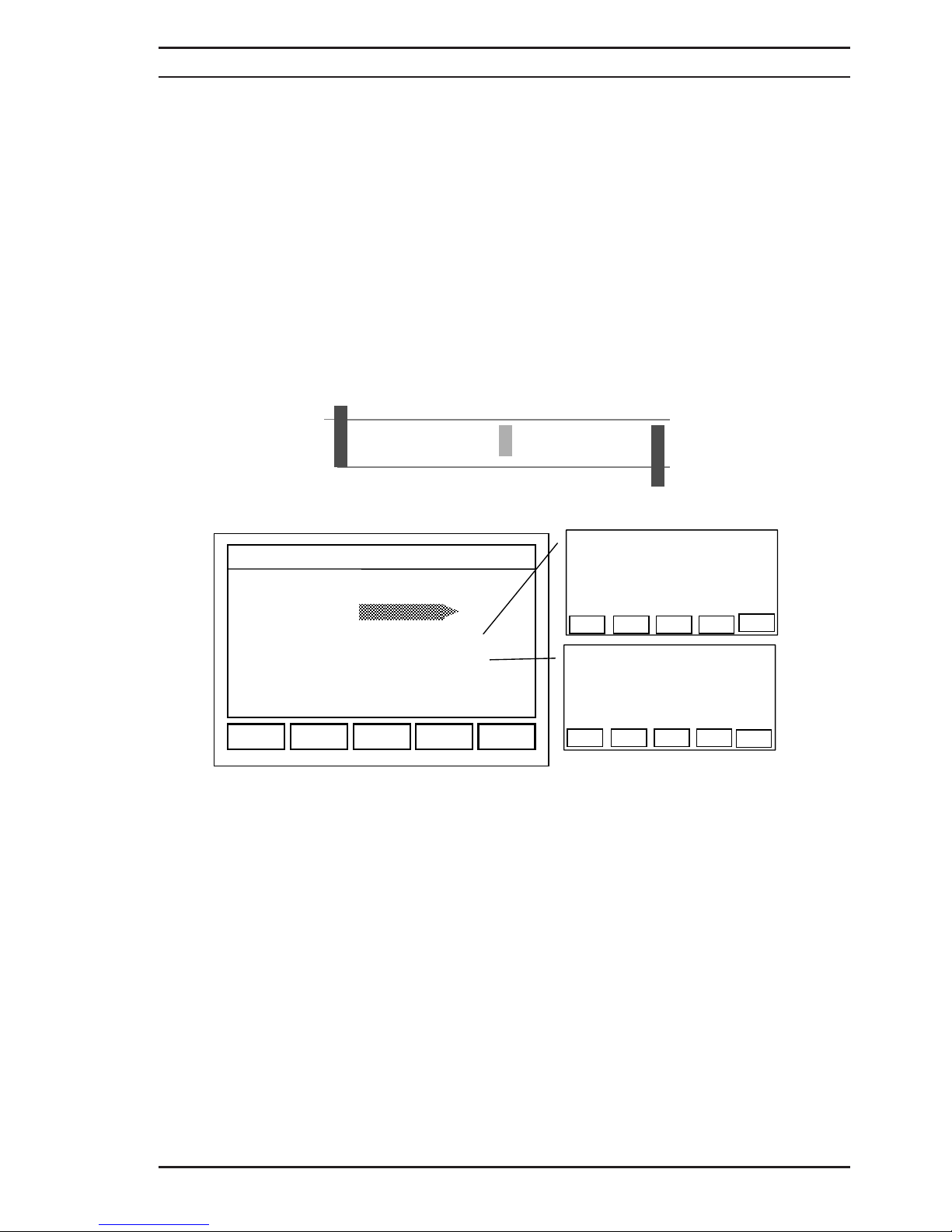
From this menu the LIMITS function may be switched ON or switched OFF. The Maximum
(MAX) and Minimum (MIN) limit value may also be selected.
To switch the LIMITS ON or OFF with the required option highlighted PRESS OK (F5) to set.
The display will return to the previous screen.
Against the MAX and MIN options the limit values previously set are displayed. To change the
limit value highlight the MAX or MIN and select with the right navigation arrow, a new window
will display. In this window the new limit value can be entered. Options to change the UNITS
or CLEAR the digits set will be found on the function keys. Once the required limit value is
set, accept with the OK function key (F5) and the display will return to the previous menu.
LIMIT PASS / FAIL
Once the limit values are set and the limit option turned ON, the DO7PLUS will monitor all
measurements to ensure that they fall inside the MAX and MIN values. For measurements
inside the limits the green Pass led on the front panel will illuminate and <<OK>> will be
displayed in the FUNCTION window of the measurement screen. If the measured value is
outside the limit range set then the red Fail led on the front panel will illuminate and the
FUNCTION window of the measurement screen will display >>Hi>> for values above the set
limit and <<Lo<< for values below.
4.9.5 DATA LOG
The DO7PLUS comes complete with a Data Logging facility. Up to 1000 readings may stored
with date and time stamp. Readings may be stored manually or logged using the built in timer.
Logged values can be reviewed in either graph or table format and statistical analysis of the
stored values may be displayed.
Number Readings
To select the number of readings to be stored in the log, highlight No. RDGS in the DATA
LOG menu screen. The number of readings currently set will be shown. Use the right
navigation arrow key to select the next screen. The number of measurements, up to 1000, to
be stored can now be entered. If the log already has stored values then these may first be
cleared with F4 function key or the new measured values added to the log. The screen will
indicate the number of free stores available.
DATALOG TIMER
OVERVIEW
The purpose of the Datalog Timer is to allow measurements to be made at a selected interval
without intervention from the user. (This can also be achieved via the remote interface, but
the timer allows this without a PC).
Low limit
High limit
Measurement higher
than set limit = FAIL
Measurement within
set limits = PASS
Measurement lower
than set limit = FAIL
INSTRUMENT MENU
DATA LOG:
20
OFF
OFF
ON
REVIEW
DELETE
No. RDGS
TIMER
STATS
GRAPHICS
ESC
OK
REVIEW
NUMBER OF
READINGS:
(1 -- 1000)
(971 FREE)
ESC CLEAR
OK
INTERVAL
TIMER: 00:00:00
(HH:MM:SS)
ESC CLEAR OK
Operating Instructions
Digital Microhmmeter Type DO7 PLUS
23
Page 25
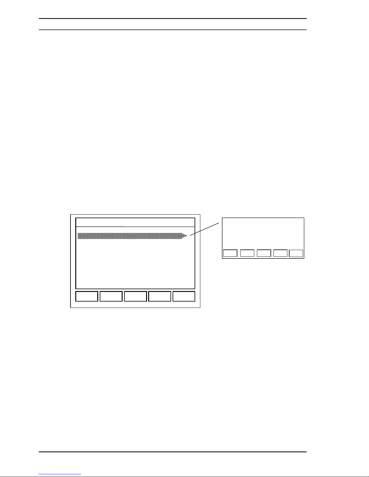
Once set up, and the measurement is started, an immediate measurement is taken, followed
by the prescribed number of measurements at the selected timer intervals.
The difference between SINGle and CONTinuous measure mode is that in SING, the
measuring current is applied only during each measurement, whereas in CONT mode, the
current is on all the time, allowing for example, timed measurements of an inductive load.
TIMER SETTINGS
In the Datalog menu, the Timer can be set in HH:MM:SS format from 00:00:00 (Off) to a
maximum of 23:59:59.
The Number of Readings can also be set from 1 to 1000 so care must be taken to ensure that
the time interval is compatible with the number of readings and the data log free capacity.
TIMER OPERATION – ADDITIONAL NOTES
x If AUTO1 autorange is set, then the top range will be set at the start of the first
measurement. After that, the autorange will operate as if it were in AUTO2 mode, ie only
change range (in either direction) if required.
x The Settling Algorithm (see section 4.9.11) is reset at the start of every measurement.
Note that in Continuous mode, like the timer-free situation, the current is disconnected
and measurement ceases at the end of a Settling Algorithm measurement.
x If in Zero current mode, a Zero measurement is only taken on the first measurement,
unless autorange changes the range.
REVIEW
Fig 4.9.5 review screen of data logged values
The logged measurements can be displayed in a table format (Fig 4.9.5)with date and time.
The log can be scrolled through using the navigation arrows and the highlighted entry can be
selected with the right arrow navigation key, notes can then be added to the entry using the
keyboard. Up to 1 line (33 characters) of text per logged value may be entered.
4.9.6 STATS
From the logged measurement values a statistical analysis can be displayed. The DO7PLUS
will automatically calculate the Maximum, Minimum, Mean value, Peak to Peak value and
Standard deviation.
Select the STATS option from the Data Log window and press the right navigation arrow to
display the first stats window. In this window the starting (FROM) and finishing (TO) logged
values to be analysed can be set. When the values have been entered press OK (F5), and
the selected logged value statistics will be displayed.
LOG# Rx DATE TIME
1 +4.9965k 28/04/08 15:35:30
2 +4.9965k 28/04/08 15:35:32
3 +4.9965k 28/04/08 15:35:34
4 +4.9965k 28/04/08 15:35:37
5 +4.9965k 28/04/08 15:35:39
6 +4.9965k 28/04/08 15:35:41
7 +4.9965k 28/04/08 15:35:43
8 +4.9965k 28/04/08 15:35:45
9 +4.9965k 28/04/08 15:35:47
10 +4.9965k 28/04/08 15:35:50
ESC
EXIT
NOTES
3 +4.9965k 28/04/08 15:35:34
LOG# Rx DATE TIME
3 +4.9965k 28/04/08 15:35:34
NOTES:
ESC EDIT
EXIT
Operating Instructions
Digital Microhmmeter Type DO7 PLUS
24
Page 26
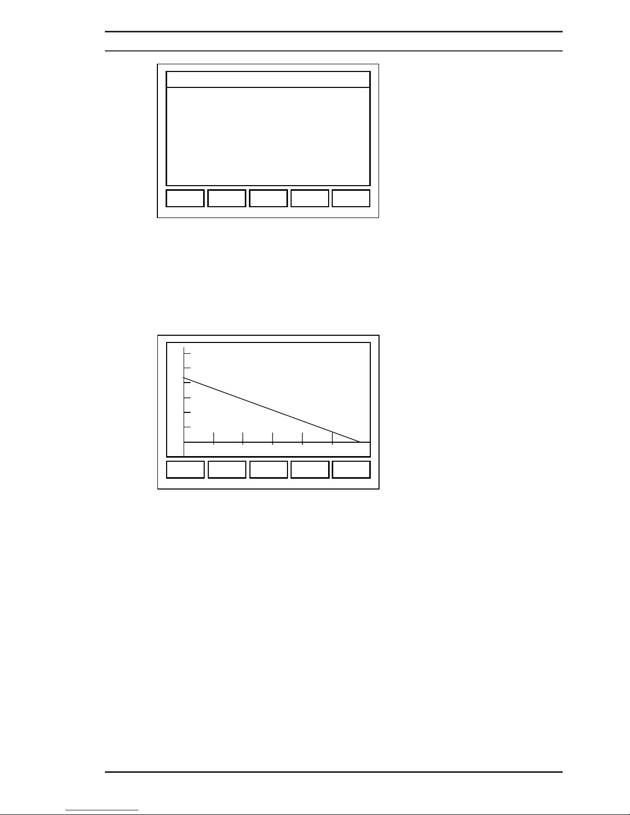
HINT: STATS will only be calculated and displayed from measurements with the same
measuring conditions. E.g. Changing ranges will prohibit the STATS display.
4.9.7 GRAPHICS
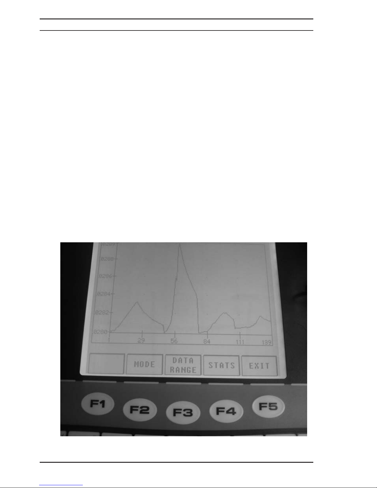
The DO7PLUS has the ability to plot graphs from the logged values. Once the datalog has
been configured and values stored, select the GRAPHICS option from the DATA LOG menu
screen using the right navigation arrow.
PRESS F3 (DATA RANGE) and enter the logged data numbers in the FROM /TO dialog box
and PRESS F5 (OK) to accept.
To select the graph type PRESS F2 (MODE) the dialog box allows the following selection.
x SCATTER
x LINEAR
x LINE FIT
x COOLING CURVE
For the COOLING CURVE additional data needs to be set up but for the other three options
the graph is automatically formatted and displayed. From the GRAPHICS window the STATS
(F4) can also be displayed for the data range selected PRESS F4 (STATS).
INSTRUMENT MENU
STATS (1 – 29):
MAX : 4.9971 k
MIN : 4.9939 k
MEAN : 4.9948 k
PTP : 0.0032 k
SD : 0.00056 k
ESC
OK
MODE
EXIT
DATA
RANGE
STATS
Operating Instructions
Digital Microhmmeter Type DO7 PLUS
25
Page 27
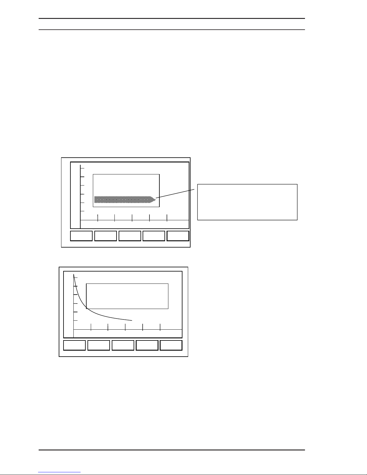
4.9.8 COOLING CURVE
The COOLING CURVE function is a very powerful feature of the DO7PLUS and enables the
maximum temperature of a machine, running under full load, to be automatically calculated
and displayed in both graphical and table formats.
Select the COOLING CURVE function using the right navigation arrow. The following can now
be set:
x TIME DELAY – This is the time between switching off the machine and the first valid
measurement.
x AMBIENT TEMPerature – This is the ambient temperature at which the measurements
are made.
x Rnom - The cold resistance measured at ambient temperature.
x Tnom - The ambient temperature at which Rnom is measured
x TEMPerature. COEFFicient - This is the temperature coefficient for the material being
measured, for a motor winding this is normally copper. This is automatically selected from
the coefficients set in the TEMPerature COMPensation Mode which must be switched ON
NOTE: When the temperature compensation is switched on then AMBIENT TEMPerature and
Tnom will be the temperature compensation reference value, normally 20qC.
Fig: 4.9.8 Cooling Cuve display
IMPORTANT
When datalogging readings, for use with the COOLING CURVE function, the following should
be set:
x CURRENT = +I
x TRIGGER = Continuous
x AUTORANGE = OFF
x TEMPerature COMPensation = ON with Pt100 sensing
x FILTER = OFF
x SETTLING = OFF
x COEFFicient should be set for correct material
MODE
EXIT
DATA
RANGE
STATS
SCATTER
LINEAR
LINE FIT
COOLING CURVE
COOLING CURVE
TIME DELAY 10 s
A
MBIENT TEMP. 25.0qC
Rnom 12.0000
Tnom 20.0qC
TEMP. COEFF. 3930.0 ppm/qC
MODE
EXIT
DATA
RANGE
STATS
R at Time 0 = 12.4716
Temp. At Time = 29.2
q
C
Temp. Rise. = 9.2
q
C
Operating Instructions
Digital Microhmmeter Type DO7 PLUS
26
Page 28
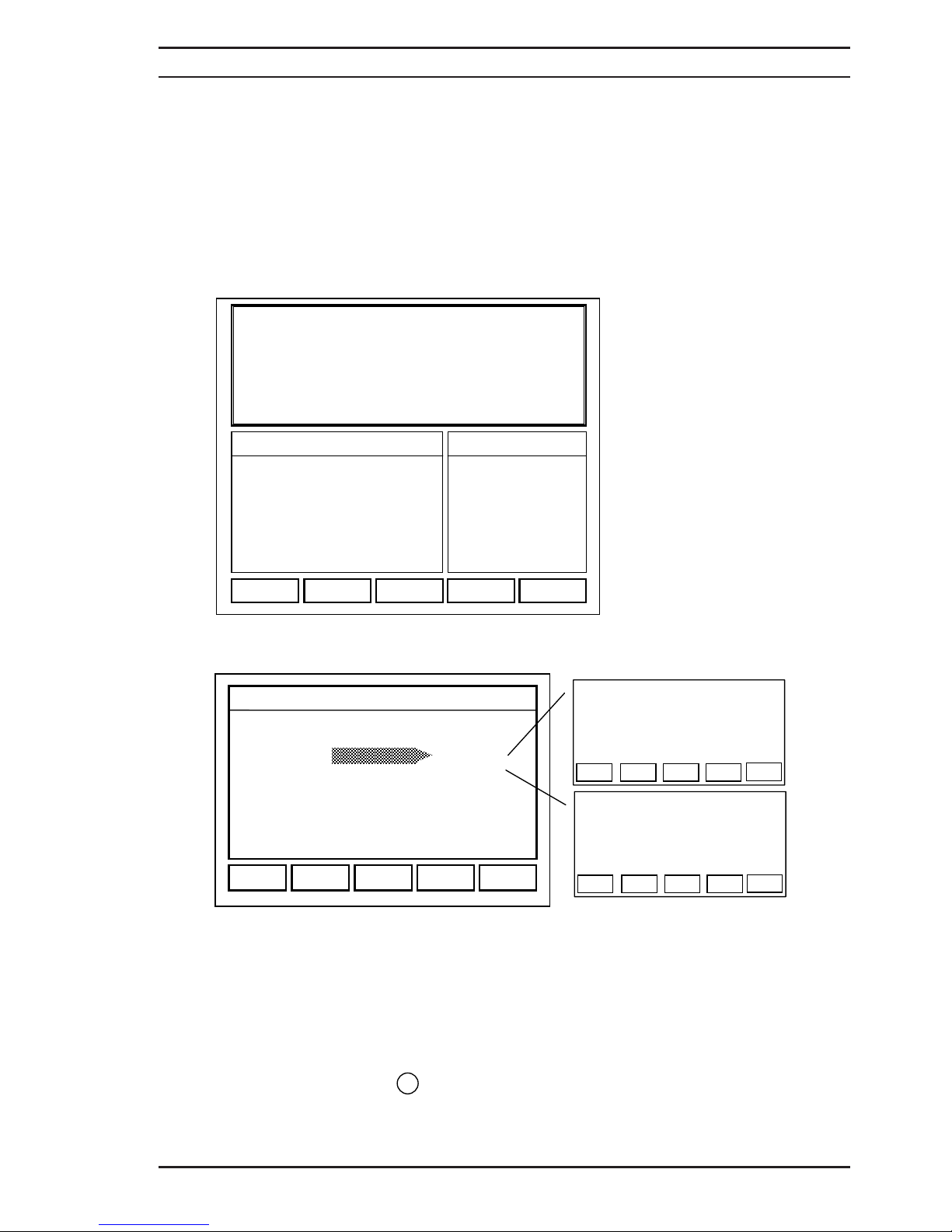
4.9.9 TEMPerature COMPensation
Temperature compensation is included in the DO7PLUS and should be used when
measurements are required to be referenced to a set temperature, normally 20qC. This is
particularly useful when measuring materials with a high temperature coefficient such as
copper. As the ambient temperature varies so will the resistance value of the copper. Using
the temperature compensation mode references all values back to a reference temperature.
The DO7PLUS displays both the temperature compensated value, and the true resistance
value measured, together with the reference temperature and the actual measurement
temperature. This ensures that the user has all the measurement information and reference
conditions readily available.
Fig:4.9.9 Measurement Display screen in temperature compensation mode
Setting the Temperature Compensation Parameters
From the MENU window F3 the temperature compensation can be switched ON or OFF. The
measurement temperature can also be set to either MANUAL or Pt100. If the Pt100 option is
selected then the ambient temperature will be measured with a Pt100 temperature sensor
(available as an option). If the Manual option is selected using the right navigation arrow, then
a new window permits the entry of the required temperature over the range 0 to 100qC
HINT: Once the manual temperature is selected this temperature value is used for all
measurements. This mode should only be used in known stable ambient conditions.
If the Pt100 option is chosen then a Pt100 sensor should be connected to the front panel
socket see section 2.2.1 The Pt100 sensor will continuously measure the ambient
temperature and correct the measured resistance values accordingly.
HINT: For best measurement results always use the Pt100 mode.
INSTRUMENT MENU
TEMP COMP: OFF
ON
TEMP MANUAL
COEFF Cu (3930)
REF TEMP 20.0 qC
ESC
OK
TEMP: PT100
MANUAL 18.00qC
ESC OK
TEMP
COEFF: Cu (3930)
Al (4030)
USER 1
USER 2
ESC OK
RANGE: 6k 100μA (+VE)
+5.0589 k
@ +20.0qC
FUNCTION STATUS
TRIGGER
LIMITS
FILTER
SETTLING
DATA LOG
SING
OFF
OFF
OFF
OFF
BATT
(3V)
BATT
(6V)
98%
92%
STOP
RANGE
CURR MENU SET UP
Rx: +5.0281 k @ +18.00 qC
11
Operating Instructions
Digital Microhmmeter Type DO7 PLUS
27
Page 29
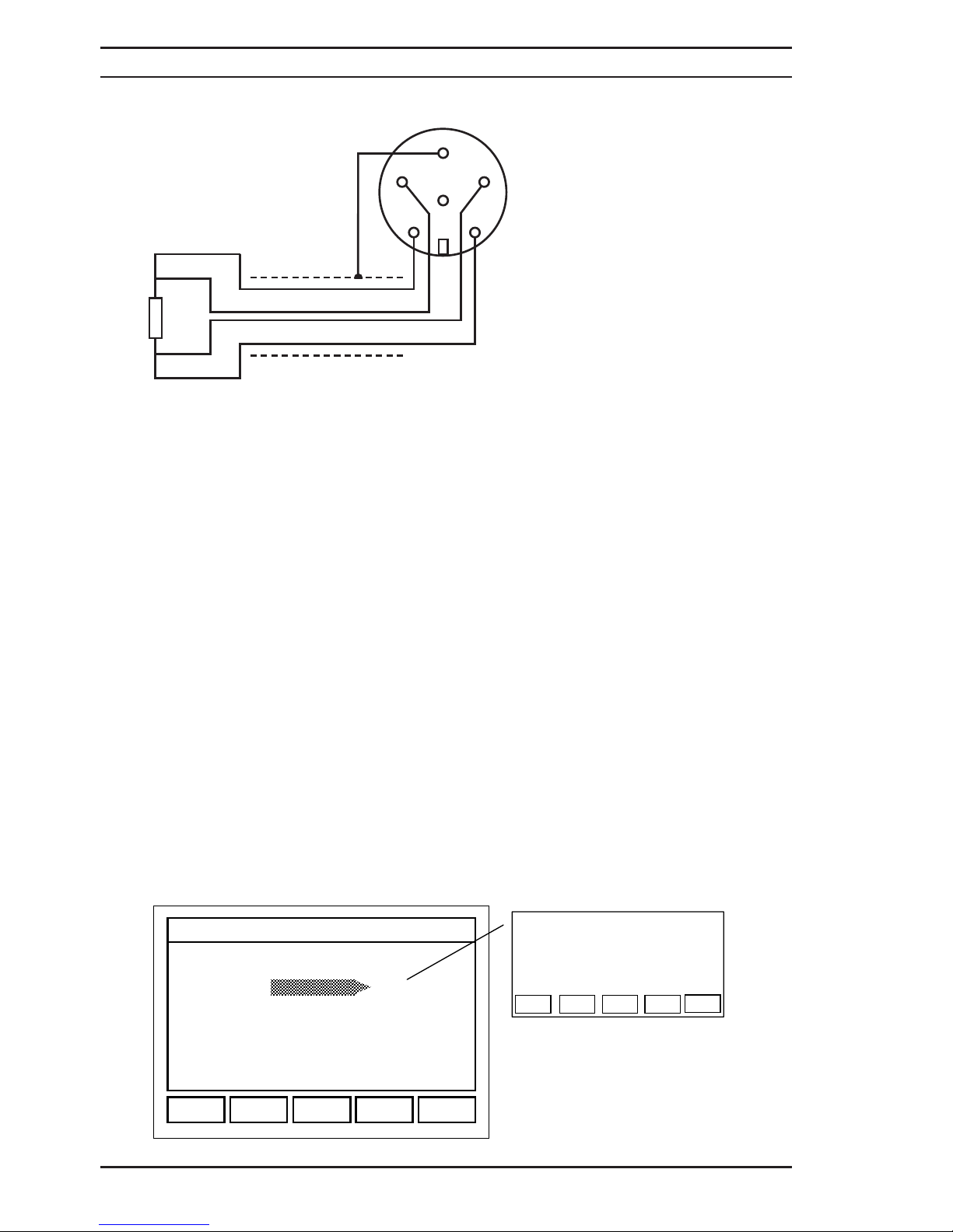
COEFFicients
Different materials have different temperature coefficients, which mean that their resistance
changes by different amounts with temperature. The most common materials used for making
electrical components are copper and aluminium and the coefficients for these materials can
be selected from the COEFF window. It may be necessary to measure other materials and
provided the temperature coefficients are known they can be entered in one of the USER
configurations. Select USER 1 using the right navigation arrow and the material temperature
coefficient can be entered in the range 0 to 9999 ppm/qC. When entered, PRESS OK (F5) to
accept and store the value and return to the previous window.
REFerence TEMPerature
The temperature compensated measurements are normally referenced to a temperature of
20qC but sometimes circumstances or test specifications require a different reference
temperature. Select REF TEMP in the temperature compensation window using the right
navigation arrow and then enter the required reference temperature in the range 0 to 50qC
4.9.10 FILTER
The measurement filter is a rolling average filter and should be used to smooth the display
reading, when measuring unstable samples. The DUT (Device Under Test) may be sensitive
to small changes in temperature, in which case the displayed value would be fluctuating,
making it difficult and uncomfortable to read the measured values. In these cases the FILTER
may be switched ON and a number of readings averaged the number of readings selected to
average will depend upon the severity of fluctuation, but 2 to 5 is normally sufficient. From the
FILTER set up screen readings may be set between 2 and 50. The average displayed is a
rolling average which means that if the filter was set to 5 then five measurements are taken
and averaged and the result displayed. The next reading would be added to the first five, and
the first reading deleted a new average would then be displayed.
ESC CLEAR OK
INSTRUMENT MENU
FILTER : OFF
ON
TEMP 10
RESET
ESC
OK
NUMBER OF
READINGS:
(2 -- 50)
No RDGS
No RDGS
Pin numbers as viewed from rear of plug
(cable side)
x PIN 1 ...Screen
x PIN 2 ...+U
x PIN 3 ...+I
x PIN 4 ...-I
x PIN 5 ...-U
x PIN 6… NC
Connections for Pt100 sensor
Operating Instructions
Digital Microhmmeter Type DO7 PLUS
28
+I
1
2
5
6
4
3
+U
Pt100
-U
-I
Page 30
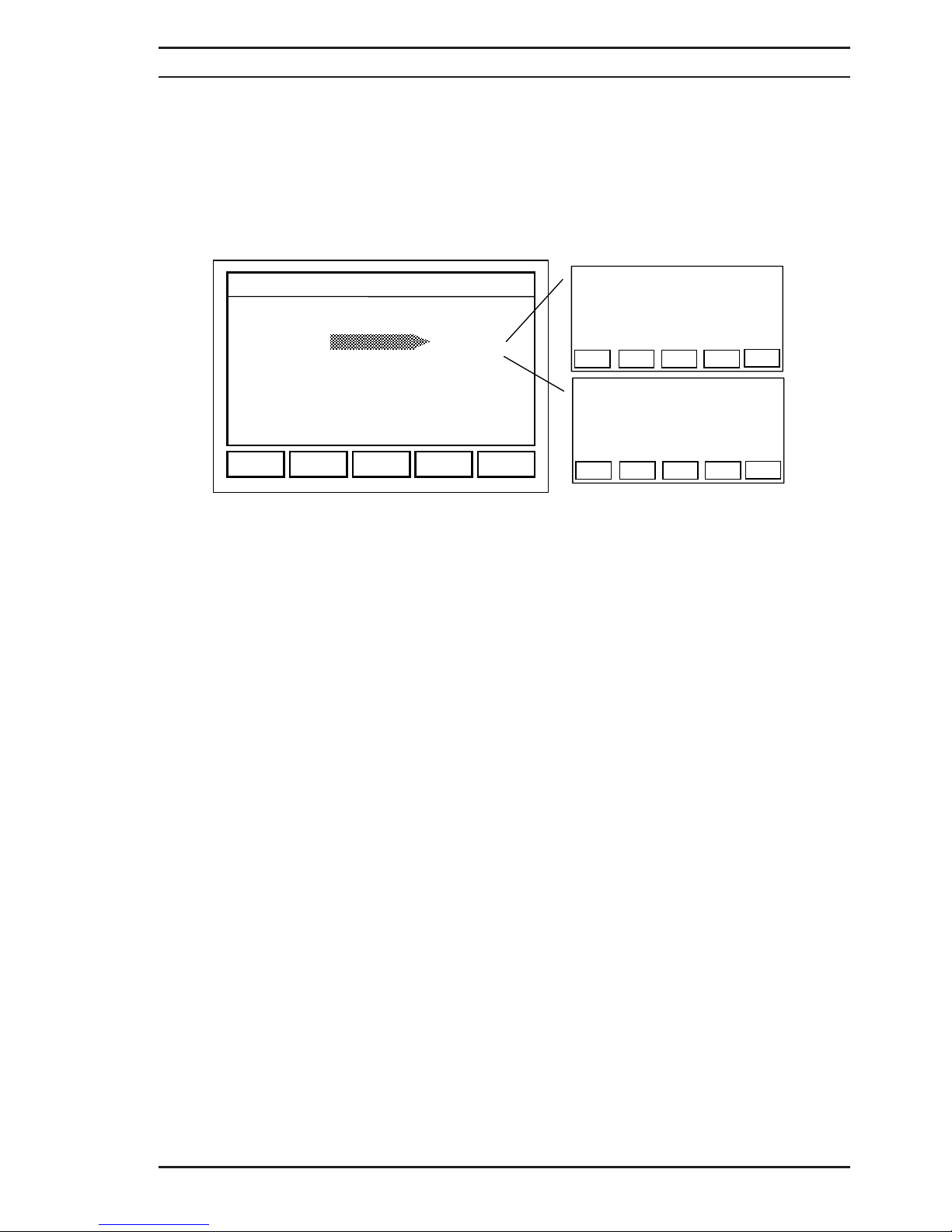
4.9.11 SETTLING
The settling algorithm is particularly useful when measuring inductive devices such as motors,
generators and transformers. With such devices it can take several seconds, and in the more
extreme cases minutes, for the ohmmeter measuring current to charge the inductance and
provide a steady and stable reading. When the settling algorithm is selected, and the
‘MEASURE’ button pressed, continuous measurements will be made until the number of
consecutive readings is within the selected limit. The value will then be displayed. If the
selected number of readings is reached without the measurements settling an error message
will display and the measurement stopped.
From the Settling mode window the settling function may be switched on or off. The number
of settling readings and the limit of the readings may also be set.
NUMBER of READINGS
Highlight and selected, using the right navigation arrow, No RDGS in the settling window. The
reading number can now be entered in the range 2 to 999.
This is the number of consecutive readings in which the measured values must fall within the
limits set before that value is displayed.
SETTLING LIMIT
Highlight and select, using the right navigation arrow, LIMIT and enter the number of digits in
the range 1 to 999.
This is the number of display digits by which the number of readings set may differ for the
measurement to be defined as settled. The settled value will then be displayed.
If the readings do not then an error message “FAILED TO SETTLE” will be displayed and the
measurement stopped.
The settling function should normally be used in the Single trigger mode, but if continuous
mode is used the operation is the same except that once the measurement has settled the
measurement will stop and the measurement current disconnected.
EFFECT ON OTHER FUNCTIONS
Selecting the Settling facility will:
x Cause the Autorange to change range in a downward direction only.
(Therefore, only ‘Auto1’ autorange mode should normally be used.)
x Deselect the Filter function.
x Change Average current mode to Positive current mode.
PARAMETERS WHICH WILL DESELECT THE SETTLING FACILITY
The Settling facility will be deselected if:
x Filter facility is selected.
x Average current mode is selected.
INSTRUMENT MENU
SETTLING: OFF
ON
TEMP 2
LIMIT 2
ESC
OK
NUMBER OF
READINGS:
(2 -- 999)
ESC CLEAR OK
No RDGS
SETTLING
LIMIT: DIGITS
(1 -- 999)
ESC CLEAR OK
Operating Instructions
Digital Microhmmeter Type DO7 PLUS
29
Page 31
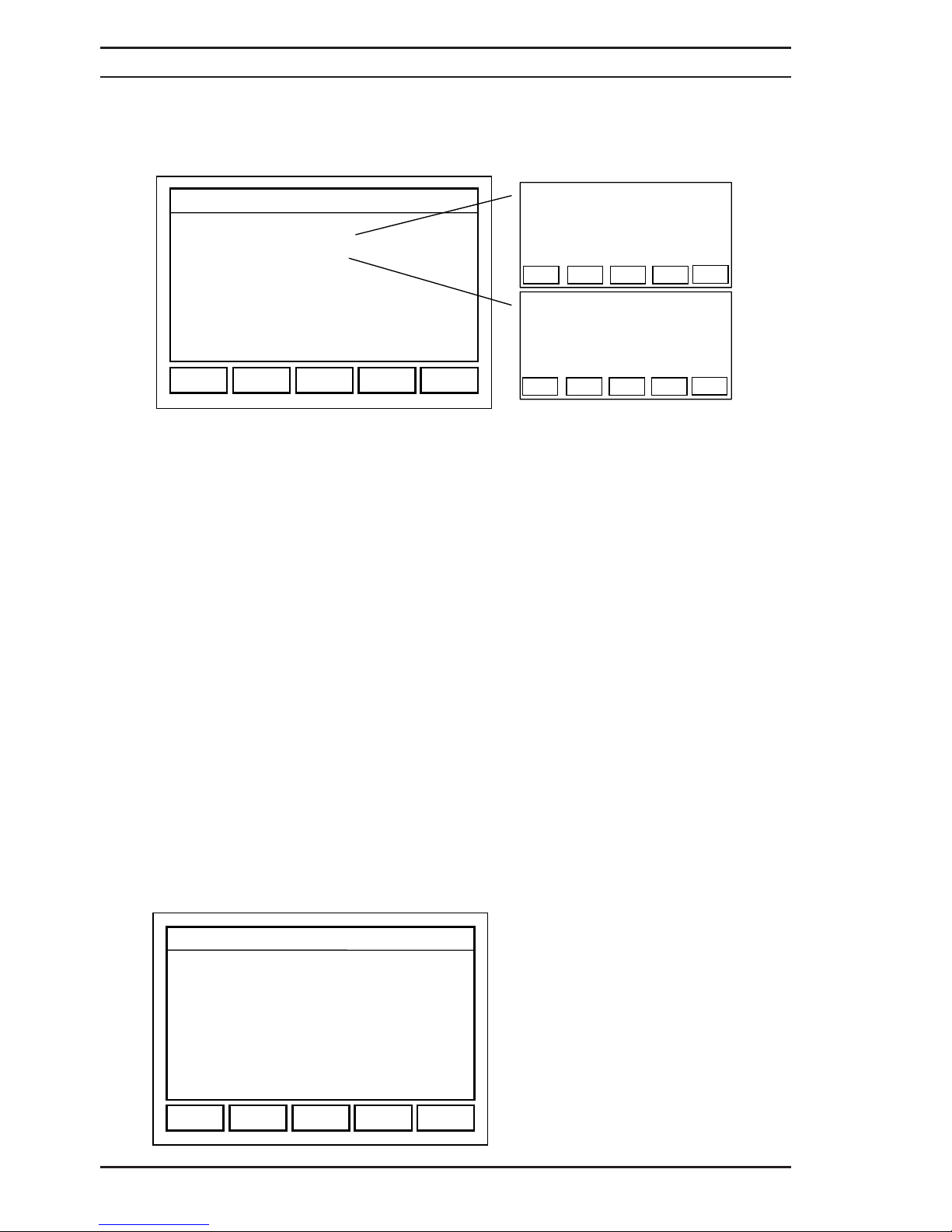
4.9.12 CABLE MODE
When the CABLE MODE is selected the DO7PLUS can be used to measure and calculate
the length of cables as either an Ohms/Length or a Length value.
/ LENGTH DISPLAY
In order to obtain this, the user can enter the following:
1. No. of cables (1 – 99).
2. How they are connected (Series/Parallel).
3. Length of one cable (0 – 1000).
4. Length Unit (Metre/Kilometre).
Note that the Length Unit is for display purposes only, and no conversion is made from one
unit to the other due to under/overflow of the calculation. The Ohms unit, however, does alter
as necessary, from μOhm to MOHm.
LENGTH DISPLAY
In order to obtain this, the user can enter the following:
1. No. of cables (1 – 99).
2. How they are connected (Series/Parallel).
3. Resistance per Length of one cable (0 – 1kOhm).
4. Length Unit (Metre/Kilometre).
Note that the Length Unit is for display purposes only, and no conversion is made from one
unit to the other due to under/overflow of the calculation.
4.9.13 MEMORIES
Using the MEMORY function up to 10 DO7PLUS configurations can be stored and recalled.
Highlight and select MEMORIES, using the navigation arrows, in the MENU window. From
this window the FUNCTION keys can be used store and recall the memories. When a
memory is stored all the preset measurement parameters of the instrument will be saved,
recalling a memory will reinstate those parameters.
LENGTH
ESC OK
INSTRUMENT MENU
CABLE MODE: OFF
/LENGTH
LENGTH
ESC
OK
/LENGTH: No CABLES 1
CONN SERIES
LENGTH 1.0000
UNIT METRE
ESC OK
/LENGTH: No CABLES 1
CONN SERIES
LENGTH 1.0000 /
UNIT METRE
LENGTH
INSTRUMENT MENU
MEMORIES:
ESC LIST
RECALL
STORE
CLEAR
Operating Instructions
Digital Microhmmeter Type DO7 PLUS
30
Page 32

The status of the memory store can be displayed by pressing LIST (F5) this will show which
memories are free and which are in use. Memories can be cleared by pressing CLEAR (F4).
If a memory is in operation, this will be displayed in the Status window, if any measurement
parameter is sub sequentially changed (e.g. Range), then it will no longer be displayed.
Operating Instructions
Digital Microhmmeter Type DO7 PLUS
31
Page 33
5 MEASURING WITH THE DO7PLUS
5.1 Connecting to the DO7PLUS
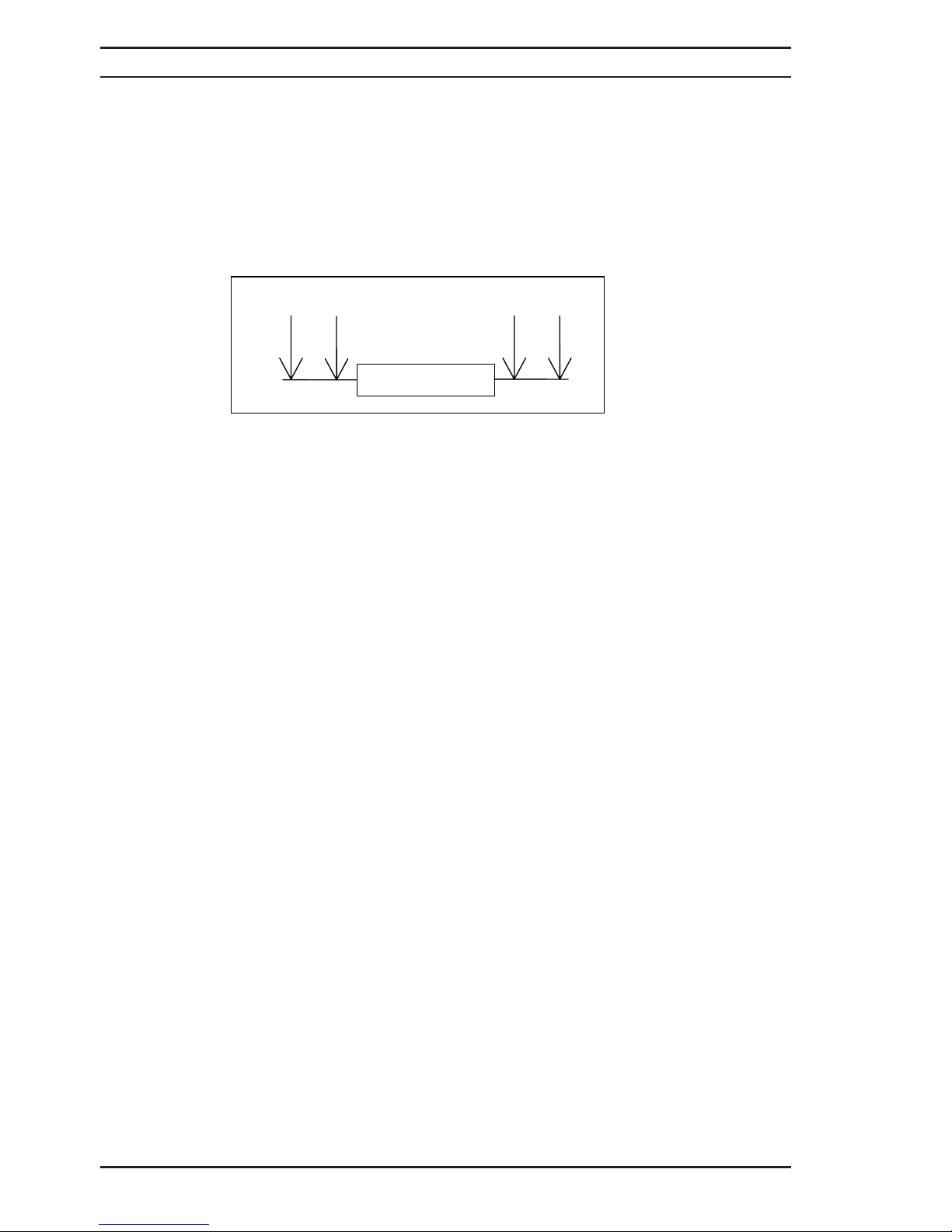
The DO7PLUS uses a four terminal method of measurement which eliminates errors due to
lead resistance. The measuring leads plug into the four front panel safety sockets. The
sockets are marked +U, -U, +I, & -I. Connections to the resistance to be measured should be
as per Fig: 5.1.1
Fig: 5.1.1 Connection diagram
HINT: It is important to connect the I (current) leads outside the U (potential) leads
5.2 Connecting to the resistance
The Digital Microhmmeter DO7PLUS employs a four wire method of measurement, i.e. it is
necessary to make four connections to the resistance under test. The instrument is supplied
with four leads; two for the potential connections which are made across the test resistor at
the points between which the resistance is to be determined; and two for the current
connections which connect the test resistor to the current supply circuit.
Connect to the resistance under test as shown in figure 5.1.1, Cleanliness is important and if
the sample is not clean, a rub with an abrasive paper to remove oxides is recommended.
It is not always possible to use the combined current and potential crocodile clips (Kelvin
clips), in which case test leads with spade tags, or special fixtures may have to be made to
suit the particular application. We offer a variety of different lead and fixture types which are
list in section 9
Rx
+I
+U
-I
-U
Operating Instructions
Digital Microhmmeter Type DO7 PLUS
32
Page 34
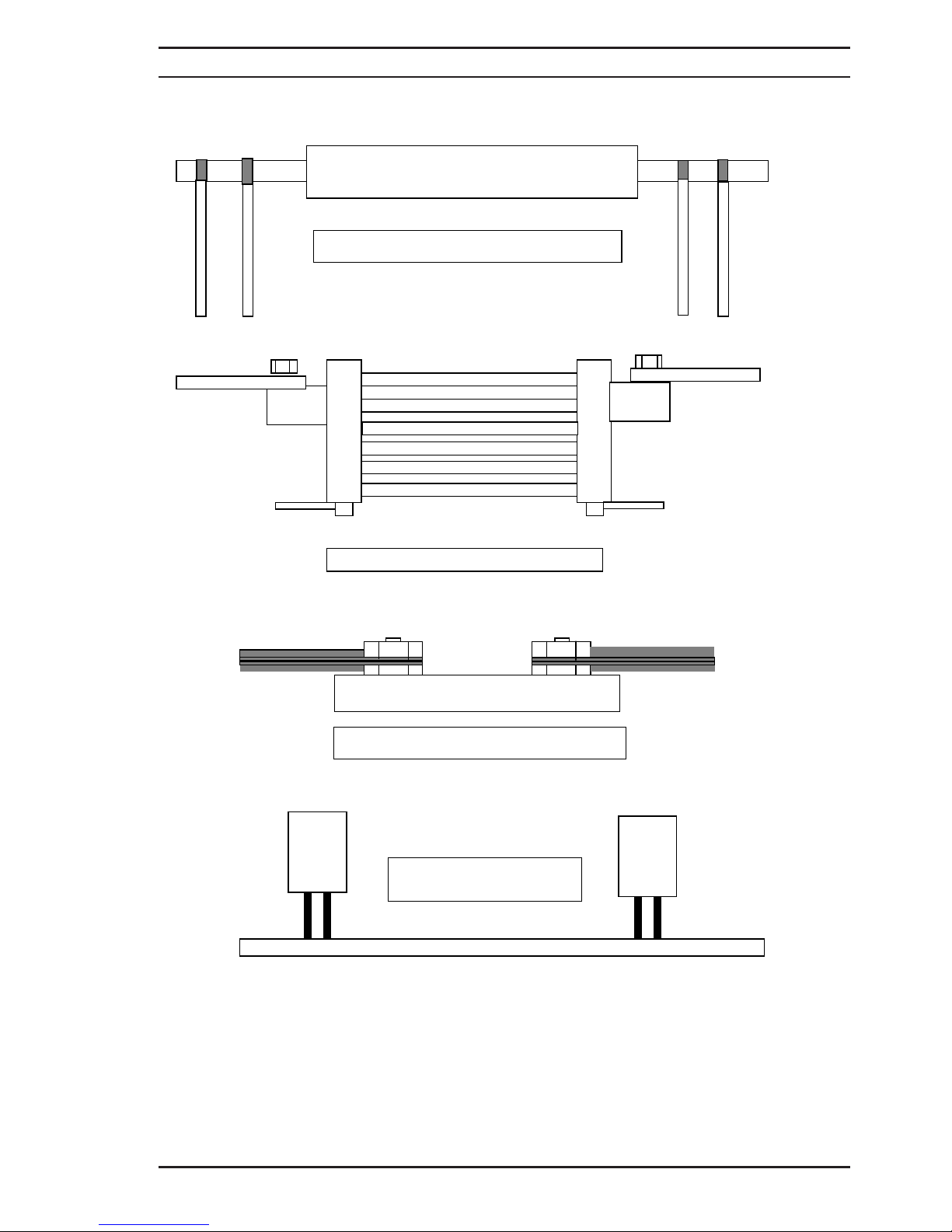
Fig: 5.2.1 Diagram of different connection configurations
+I +U -U -I
+I
-I
Connections to Current Shunt
+U -P
Connection to Cable Joint
+U -U
Connections to Stud Terminals
+I
-I
+I
+U
-U
-I
Measurement with duplex
handspikes
Operating Instructions
Digital Microhmmeter Type DO7 PLUS
33
Page 35
5.3 Resistance measurement
The DO7PLUS should be in the measurement [STOP] mode. In this mode the measuring
current is switched off and the current terminals are shorted internally. Connect the measuring
leads as described in section 5.1 Before starting the measurement select the current mode
required as described in section 4.6. Select the range required see 4.5 or auto range.
WARNING the maximum measuring current is 10 Amp on the lowest measuring range ensure
that the current level selected will not damage the resistance being measured
To start the measurement press the MEASURE button the measured resistance value will be
displayed.
5.4 Resistance measurement with temperature compensation
Temperature compensation should be used when measuring the resistance of materials
which have a high temperature coefficient. Copper, for example, has a temperature coefficient
of 0.3930%/K. The value of the resistance measured will therefore vary with the temperature
of the copper. To obtain consistent and meaningful results, the resistance values may be
related to a set ambient temperature, normally 20qC.
Example: Copper with a temperature coefficient of 3930ppm/k = 0.3930%/k
To measure with the temperature compensation, proceed as in 5.3 but in addition connect the
temperature sensor probe (see section 9 for accessories details and part numbers) to the
front panel socket. Select the temperature compensation measurement mode as described in
4.9.9. Alternatively, if the ambient temperature is stable, a manual value may be entered, in
this case a temperature sensor is not required. The compensated resistance value will be
displayed in large digits on the DO7PLUS screen and the true measured resistance value will
be shown in smaller digits below the main display. The measured and set temperature will
also be shown.
5.5 Effects of Lead Resistance
The DO7PLUS is a true four terminal measuring instrument and will, therefore, measure
accurately with long lead lengths. The DO7PLUS monitors the lead resistance and will display
an error message if the lead resistance exceeds the resistance values below. It is good
practice to keep the lead lengths to a minimum, this ensure that any magnetic fields and other
environmental noise that may be present have minimal effect. Sometimes long leads can’t be
avoided and in these cases the cable resistance should be kept to a practical minimum and
not exceed the following:
x Current Leads Maximum resistance 60m each lead (120 m total)
x Potential leads Maximum resistance 1keach lead (2k total)
HINT: The accuracy of the measurement is not affected by different lead lengths, only by the
resistance of the leads.
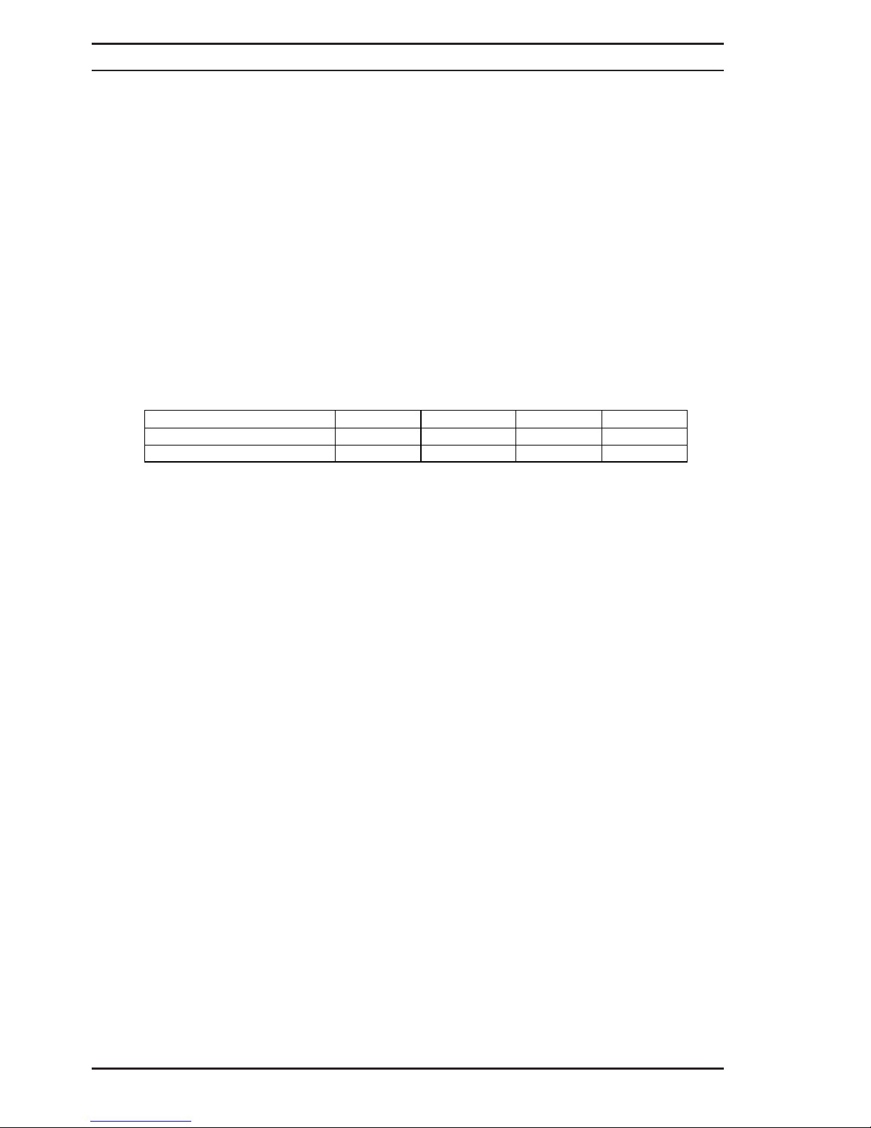
Temperature
20qC 25qC 30qC 35qC
Resistance of Copper
18.000 m: 18.354 m: 18.707 m: 19.061 m:
% Increase in resistance 0% 1.96% 3.93% 5.89%
Operating Instructions
Digital Microhmmeter Type DO7 PLUS
34
Page 36
6 CALIBRATION
The DO7PLUS is designed with ease of calibration in mind and comes complete with a
manufacturer’s calibration certificate. A UKAS calibration certificate is also available and
should be ordered with the instrument if required. The calibration should be verified annually
and if necessary adjusted. The unit may be returned to CROPICO who offer a full calibration
service.
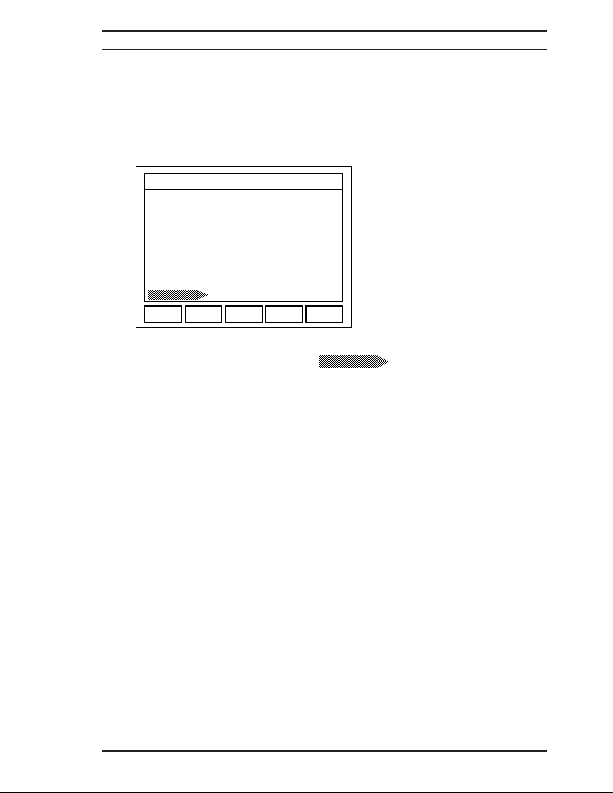
For those who wish to perform their own calibration, enter the calibration mode by pressing
F4 (SET UP) scroll down the options and highlight CAL in the menu.
HINT: To navigate around the screen use the navigation arrows
Where an item is highlighted with an arrow
This indicates that additional options are available for that parameter and the right
navigation arrow should be pressed to reveal those options.
The display will prompt you to enter a PASSCODE. The factory default passcode is 9252.
Press F5 (OK) once the passcode is entered and the last calibration date and time will be
displayed.
BACKLIGHT
SETUP MENU
BEEPER ON
DATE FORMAT DD/MM/YY
DATE 29/04/08
TIME 16:23
LANG ENG
LINE FREQ 50HZ
TEMP UNIT GC
REMOTE 9600
VERSION VER 1.0
PASSCODE
EXIT
CAL
CAL
Operating Instructions
Digital Microhmmeter Type DO7 PLUS
35
Page 37
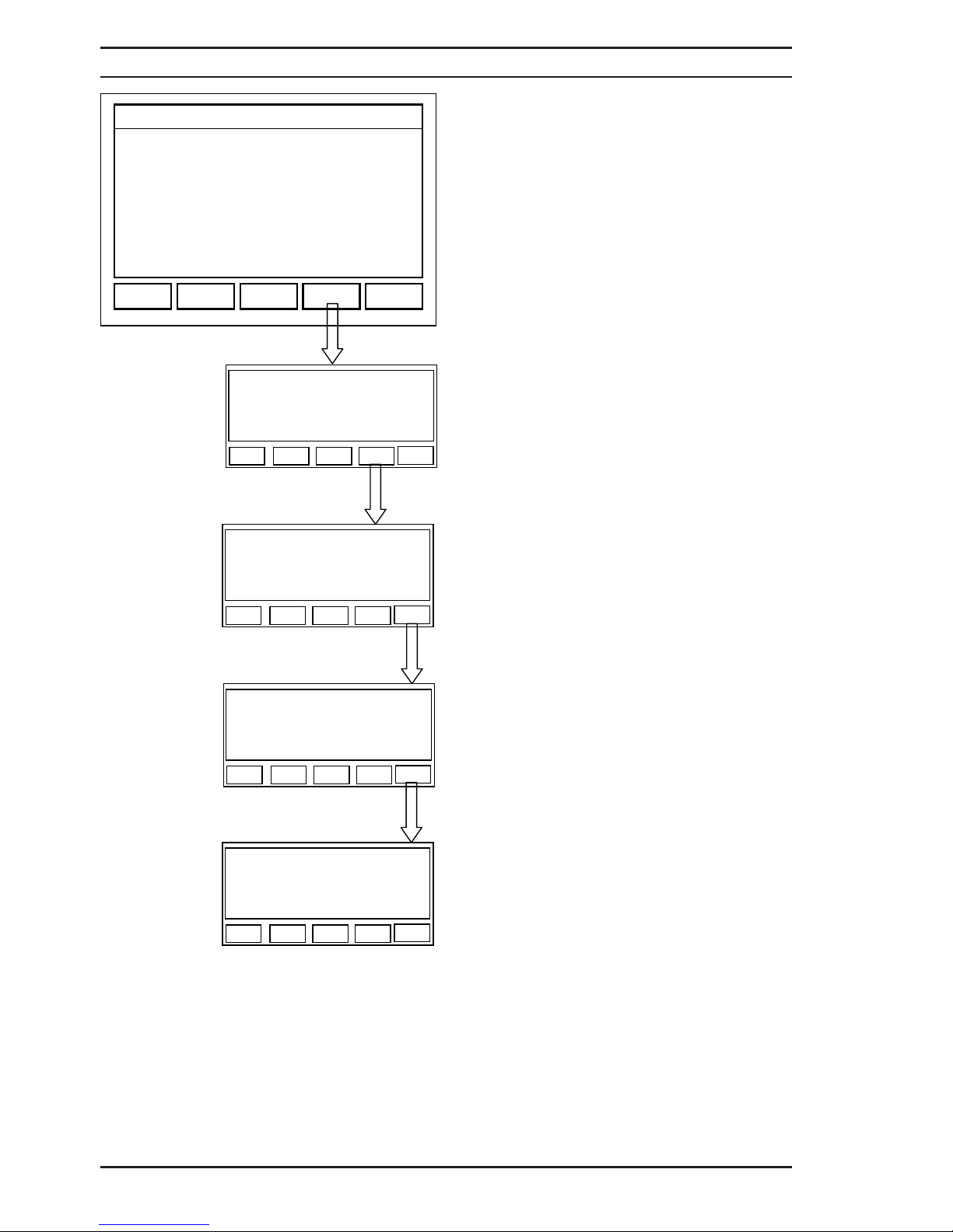
The calibration procedure prompts
you with each step. To calibrate the
Main ADC disconnect all measuring
leads and press OK (F5)
The instrument Serial number is
displayed and may be edited
The display will indicate that the 6k range is to
be calibrated at the zero point. Connect a true
four terminal zero to measuring terminals.
The display will now prompt you to calibrate the
full scale value. Connect the appropriate
calibration standard and enter its certified
value. Note: the certified value should be
entered and not the nominal value. Press OK
(F5) and the DO7PLUS will automatically
calibrate the range full scale
The calibration window will now move on to the next range value and the zero and full scale
calibration repeated. At any time you can move back to a previous range with the << keys or
move forward skipping a range with the >> keys.
For simple and easy calibration CROPICO offer a calibration standard model MTS2 which
has all the standards required in a single switched unit. With the MTS2 true four terminal zero
can also be selected.
Once all the ranges are calibrated for zero and full scale the calibration window then selects
and displays the Pt100 calibration values. First 100 is requested and a 100 four terminal
standard should be connected to the Pt100 input socket. Pressing OK accepts the value and
the window requests that 150 be connected. Again pressing OK accepts the value and the
calibration is complete.
CALIBRATION
LAST CALIBRATION:
DATE: 28/04/08
TIME: 11:41:31
ESC
>>
ESC EDIT
>>
<<
SERIAL NUMBER
12345
ESC OK
>>
<<
Calibrate Main ADC:
ESC OK
>>
<<
RANGE: 6k
ZERO
ESC
OK
>>
<<
RANGE: 6k
ENTER VALUE OF STANDARD:
k
Operating Instructions
Digital Microhmmeter Type DO7 PLUS
36
Page 38
HINT: The standards used should have a minimum certified accuracy of ± 0.01% and the
DO7PLUS should be placed in a temperature controlled environment at least four hours
before calibration.
Once the ranges and Pt100 sensor ranges are calibrated the menu moves on to reset the
battery Gas gauges. With fully charged batteries connected, highlight the 3V (ANALG) and
press OK repeat for the 6V (DIG) battery
7 UPDATE FIRMWARE
The next window permits the updating of the DO7PLUS firmware, CROPICO has a
programme of continual improvement and firmware updates will be available from time to
time. These update will be available on CD or may be downloaded from our website
www.cropico.com. The updates may be uploaded via the USB or RS232 interface and full
instructions will be provided.
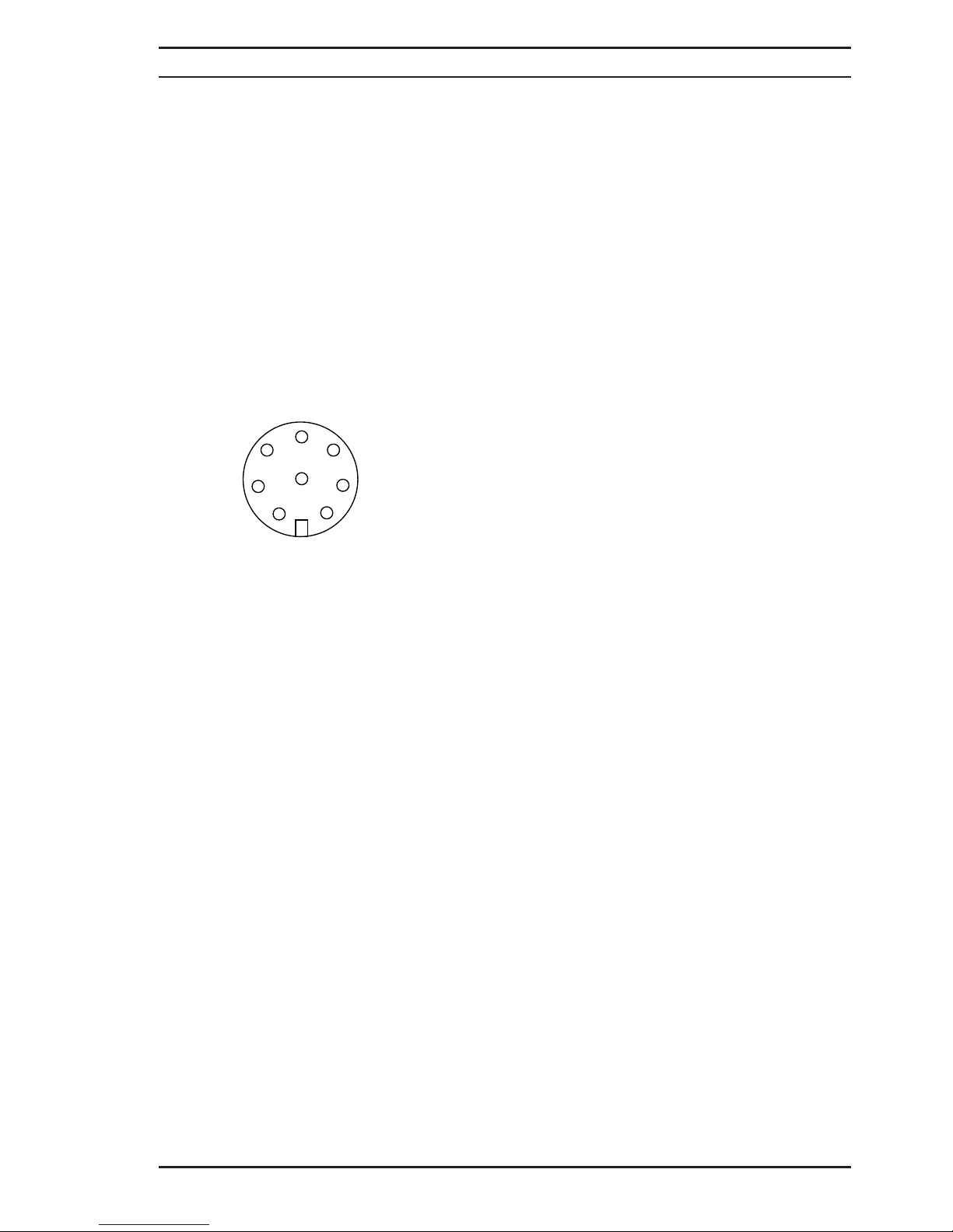
8 RS232 CONNECTION DIAGRAM
DO7PLUS RS-232 CONNECTION SOCKET
Pins numbered as viewed from rear of plug (cable side)
x PIN 1 ... REMOTE START
x PIN 2 ...RXD
x PIN 3 ...TXD
x PIN 4 ...N/C
x PIN 5 ...GROUND
x PIN 6 ...N/C
x PIN 7 ...RTS
x PIN 8 ...CTS
1
2
3
4
5
6
7
8
Operating Instructions
Digital Microhmmeter Type DO7 PLUS
37
Page 39
Operating Instructions
Digital Microhmmeter Type DO7 PLUS
38
9 ACCESSORIES
MEASURING LEADS
The DO7PLUS may be used with a variety of lead sets. The following are the available
selection. Remember, if you do not see suitable leads for your application, please consult our
customer help desk.
Ordering
Code
Description
HS01-P Duplex Handspikes with 2.5 metre lead length, current and potential
spikes suitable for plate or Bussbar measurements.
HS02-P Duplex Handspikes as a HS01-P but with 2.5 and 15 metre lead lengths
LS03-P Large Kelvin clips with 3 metre lead length suitable for attaching to rods
bars or cables up to 38mm diameter
LS04-P As LS03-P but with lead lengths 3 and 15 metres
LS05 Executive lead set consisting of 4 x 1 metre leads with banana plugs, 4 x
crocodile clips 4 x test prods and 4 x Kelvin clips (KC1) jaw opening
4mm
LS06-P Kelvin lead set comprising of miniature Kelvin clips (KC2) with 1 metre
leads attached terminated with banana plugs Jaw opening 6mm.
Suitable for fine wires.
WIRE CLAMPS
For the precise measurement of 1 meter cable samples we offer 3 wire clamp options.
Ordering
Code
Description
C02 1 metre wire clamp with hardwood base suitable for cable diameters up
to 100mm
C02-A 1 metre wire clamp with metal base and provision for temperature
sensor suitable for wire cross section 1 to 1000mm
CO3 1 metre wire clamp with water bath for the precise measurement of 1
meter cable samples 1 to 1000mm
TEMPERATURE PROBE
Ordering
Code
Description
5000-Pt100 Pt100 Temperature Sensor Probe length 200mm, diameter 6mm. Fitted
with 1 Metre Lead and DIN Plug
Ordering
Code
Description
MTS2 Calibration Standard
Page 40

SECTION 2
REMOTE CONTROL INTERFACE
FOR
DO7PLUS
DIGITAL MICROHMMETER
USER MANUAL
CONTENTS
1.
INTRODUCTION...........................................................................................38
2. SETTING UP THE COMMUNICATION LINK .....................................................38
2.1 RS-232 SERIAL PORT .............................................................................38
2.2 USB PORT .............................................................................................39
2.3 FRONT PANEL SET-UP ...........................................................................39
2.4 CONFIGURING THE APPLICATION...........................................................40
2.5 COMMUNICATING...................................................................................40
3. PROGRAMMING THE INTERFACE .................................................................41
3.1 INTRODUCTION .....................................................................................41
3.2 REMOTE INTERFACE COMMANDS...........................................................43
3.3 CONFIGURATION COMMANDS ................................................................44
3.4 TRIGGER & MEASURE COMMANDS .........................................................44
3.5 DATALOG COMMANDS............................................................................46
3.6 TEMPERATURE COMPENSATION COMMANDS..........................................47
3.7 MEASUREMENT LIMIT COMMANDS .........................................................48
3.8 FILTER (ROLLING AVERAGE) COMMANDS ...............................................49
3.9 SETTLING ALGORITHM COMMANDS........................................................49
3.10 SYSTEM RELATED COMMANDS...............................................................50
APPENDICES
I Command Summary
II RS-232 Pin Connections
Operating Instructions
Digital Microhmmeter Type DO7 PLUS
39
40
40
40
41
41
42
42
43
43
45
46
46
48
49
50
51
51
52
Page 41

I. INTRODUCTION
The Remote Interface permits full remote control of the DO7PLUS by an external
computer. Commands enable the instrument parameters to be set and checked,
measurements to be triggered, and the results obtained.
The connection between the DO7PLUS and the external computer can be made
using either an RS-232 Serial Port cable, or a USB cable and driver. The RS-232
Serial Port is robust and simple to use, and the USB Port is useful for computers
which do not have a Serial Port. See Section II.A or 0 as appropriate for
information on how to set up the port.
Selection of the remote interface Baud Rate and Talk-Only mode are accessed
from the front panel ‘Set Up’ menu (see Section II.B).
A PC application is required to control the DO7PLUS, and this will need to be
configured (see Section II.C).
The remote commands are common to both connection methods, and generally
follow the SCPI / IEEE488.2 format (see Section III).
Note that the command “SYSTem:REMote” must be sent before the DO7PLUS will
recognise remote commands or queries (see Section III.B).
II. SETTING UP THE COMMUNICATION LINK
A. RS-232 SERIAL PORT
Transfer of data is controlled by hardware handshaking, and it is recommended
that the Cropico cable assembly be used for connecting the DO7PLUS to a PC.
This has the full 5-wire connection, and will maintain EMC integrity, reducing the
possibility of interference.
At the PC end, the cable should be connected to a spare Serial COM Port. Make a
note of the number of this Port if it is labelled.
FURTHER INFORMATION
The port conforms to specification ANSI/EIA/TIA-232-E-1991 "Interface Between
Terminal Equipment and Data Circuit-Terminating Equipment Employing Serial
Binary Data Interchange", except that a Remote Start connection is also provided.
A list of pin assignments is given in Appendix II.
Signal levels;
MARK (logical "1"); -3V to -15V
SPACE (logical "0"); +3V to +15V
Data is transferred using the TXD and RXD lines.
Hardware handshaking for each character transfer uses the RTS and CTS lines.
RTS is an output from the microhmmeter which indicates its receiver status. When
asserted (low) it indicates that it is ready to receive another character. When
negated (high) the microhmmeter receiver buffer is full and cannot receive another
character until the buffer is processed (if the PC sends one it may be lost). As
soon as space becomes available in the receiver buffer, RTS is re-asserted to
allow the PC to send the next character.
When the microhmmeter detects receipt of a line terminator character, RTS is
negated whilst the command line buffer is read and validated. This is to prevent the
PC sending further characters whilst a command is being validated. Following
validation, RTS is re-asserted to permit the next command to be transmitted by the
PC.
Operating Instructions
Digital Microhmmeter Type DO7 PLUS
40
Page 42

CTS is an input to the microhmmeter and controls the transmission of characters. If
the PC asserts CTS (low) then the microhmmeter will transmit the next character
from the output buffer (if one is waiting). If the PC negates CTS (high) then the
microhmmeter will not transmit the character, but will wait until CTS is re-asserted.
TXD will remain in the mark (low) condition whilst CTS is negated. Note that
changing CTS during transmission of a character will not disrupt the transmission
of that character.
If a 3-wire (TXD, RXD, GND) connection is to be used, connect RTS to CTS at the
microhmmeter end. But take care; sending characters too quickly to the
microhmmeter could cause its receiver buffer to overflow and subsequent
characters may be lost. Use a time delay between transmitted commands, or better
still, use the full 5-wire connection for reliable hardware handshaking of each
character.
USB PORT
The DO7PLUS has the option of using a USB cable to provide the data link to a
PC, as an alternative to the traditional RS-232 Serial Port cable. USB cables such
as a standard “A to Mini B” type (Cropico Part No. 551A002) can be used, or the
waterproof version.
If the PC you are using has not already been used for communicating with the
instrument via the USB interface, then the USB driver will need to be installed first.
The driver can be found on the CD supplied with the instrument, or can be
downloaded from the Cropico website http://cropico.co.uk. Follow the installation
instructions that accompany the driver.
Once the driver has been installed, the cable should be connected to a spare USB
Port on the PC, and the instrument switched on. The PC should detect this, and
confirm that the new hardware has been installed.
The driver creates a “Virtual COM Port”, and it is necessary to find out the number
of this COM Port. Typically, this can be determined by right-clicking on “My
Computer”, click on “Properties”, click the “Hardware” tab, click on “Device
Manager”, and double click on “Ports (COM & LPT)”. You should see “Cropico
DO7PLUS USB Bridge (COMx)” listed, where “x” is the number of the COM Port.
Make a note of this number.
Note that if more than one DO7PLUS instrument is connected to one PC, then the
driver will create a separate Virtual COM Port for each instrument.
B. FRONT PANEL SET-UP
Press the “SET UP” option on the front panel and scroll down to ‘REMOTE’. This
allows selection of the Baud Rate and Talk Only mode.
BAUD RATE
The options are 9600 or 19200 Baud.
The data word format is fixed at;
Start bits; 1
Data bits; 8
Parity checking; None
Stop bits; 1
For Flow Control, Hardware handshaking is used. Software handshaking using
XON/XOFF is not implemented.
TALK ONLY MODE
Operating Instructions
Digital Microhmmeter Type DO7 PLUS
41
Page 43

This mode is useful for operations such as sending results directly to a printer
without the need for a PC.
In this mode, the interface will ignore all incoming remote commands, and the
instrument will remain in LOCAL control mode.
The result of each measurement is sent to the interface output. The value sent is
the one which appears in large characters on the instrument display. This means
that, for example, if Temperature Compensation is selected, then the compensated
resistance value will be sent. However, if the Cable Mode is selected, then the
value sent is the resistance measured, as displayed in the smaller text. See
Section III.A for output data format.
REMOTE INTERFACE STATUS ON THE SCREEN
If the DO7PLUS is in remote mode, then this is indicated in the Status box as
“REMOTE REM”.
If the Talk Only mode has been selected, then this is indicated as “REMOTE T-O”.
C. CONFIGURING THE APPLICATION
A PC application is required to control the DO7PLUS, whether custom-made
software, Cropico’s DataLogger (for downloading the Datalog contents), or a
general purpose application such as “HyperTerminal”.
The application must be configured correctly for communication to be successful.
For example, if using HyperTerminal, press the “Disconnect” button, then click on
the “File” menu, “Properties”, select the correct COM Port as described below, and
click on “Configure” for the other options. For the Cropico DataLogger, the
“Configure” option is under the “Comms” menu, which is covered in the DataLogger
Help.
COM PORT
This must be set to the correct number.
If the RS-232 Serial Port is being used, then the COM Port number is the one that
was noted above in Section A. If the number is not known, then start with COM1,
and if that does not work, try COM2 etc.
If the USB Port is being used, then the COM Port number is the one that was noted
in Section 0.
BAUD RATE
This must always be set to the rate that is selected on the DO7PLUS (see B),
either 9600 or 19200 Baud.
OTHER SETTINGS
If selectable, the following settings should also be made:
Data Bits: 8
Parity: None
Stop Bits: 1
Flow Control: Hardware
Further information is given in Section A.
D. COMMUNICATING
In order to communicate with the DO7PLUS, the command “SYSTem:REMote” must
first be sent (see Section III.B). The commands detailed in Section III can then be
used.
In order to return to local, manual mode, the command “SYSTem:LOCal” should be
sent (see Section III.B).
Operating Instructions
Digital Microhmmeter Type DO7 PLUS
42
Page 44

III. PROGRAMMING THE INTERFACE
A. INTRODUCTION
The interface is programmed in a common language which is based on SCPI
(Standard Commands for Programmable Instruments). Although similar in style, full
conformance to the SCPI and IEEE488.2 standards is not guaranteed.
The following is a brief guide to the structure and syntax of the programming
language.
Command Tree
Commands are arranged as a hierarchical “tree”, similar to the filing system trees
found in personal computers. Commands start at the root level and progress down
each level in more detail. The complete path must be specified to access the lower
level commands.
Colon (:)
The colon is used to separate command keywords and automatically move the path
down to the next level.
All new command lines automatically start at the root-level.
For the DO7PLUS, a colon must not be sent as the first character. This is treated
as a non-recognised character.
Semicolon (;)
The semicolon is also used to separate command keywords, but in this case the
path remains at the same level. This is to enable more than one command to be
included in a single command line.
This is not implemented for the DO7PLUS, as only one command per line can be
accepted. The semicolon is treated as a non-recognised character.
Whitespace (TAB or SPACE)
A whitespace character must be used to separate the first parameter from a
command keyword.
The DO7PLUS will not accept whitespace characters in the subsequent parameter
list.
Comma (,)
If a command requires multiple parameters, a comma must be used to separate
parameters from one another in the parameter list.
Query (?)
Commands ending in a query (?) indicate that a response is expected from the
instrument. This is usually a measured value or a parameter value. Commands sent
without a query instruct the instrument to perform a function. The instrument will
not output a response without a query command (except in Talk Only mode).
Common Commands (*)
Commands beginning with an asterisk (*) are called common commands and have a
precise function as defined by the IEEE-488.2 standard. All instruments behave in
an identical way. These commands are primarily concerned with control, reset,
self-test and status.
Command Syntax
Most command keywords have both a long and short form. The bus controller can
send commands in either form and also in any combination of upper and lower case
characters. Instrument responses, however, are always in the short form, upper
case.
Operating Instructions
Digital Microhmmeter Type DO7 PLUS
43
Page 45

If extra, redundant parameters are sent in a parameter list they are simply ignored.
No error is produced.
e.g. SENSe:FRESistance:RANGe 60OHM,600OHM
{ignored}
In the description of commands that follows, various symbols are used for different
features:
< parameter > represents a field name.
< ON|OFF > the vertical bar indicates OR
[ optional ] square brackets indicate optional commands or
parameters.
“string” indicates an ASCII text string.
Data Types
The bus controller can also send data in a range of formats, but the instrument
always responds in a precise format. There are four principal data types;
Numeric Parameters are decimal numbers which include an optional sign,
mantissa, decimal point and exponent. Engineering suffix units are not accepted.
Discrete Parameters have limited values e.g. SINGle, INFinite, and like command
keywords they can have long and short forms, upper and lower case.
Boolean Parameters have a single binary value. The controller can send OFF or 0,
ON or 1, but the instrument response is always 0 or 1.
String Parameters contain text as ASCII characters.
Input Data Format
Numeric data sent to the instrument should be in Ohms or Degrees unless stated
otherwise. The value can be in any standard scientific format.
e.g. 3kOhm can be sent as: 3000, 3E3, 3.000E+03, 0.3E4 etc.
The units are not sent.
Output Data Format
Non-Measurement queries ASCII character string
Measurement queries SDDDD.DDDDESDD <cr><lf>
Where S = sign (+/-)
D = decimal digit (0-9)
E = Exponential
<cr> = carriage return character
<lf> = linefeed character
Measurement queries always return values expressed in Ohms or Degrees, and the
units are omitted. Resistance values are returned with engineering exponents
reflecting the resolution and units displayed on the instrument’s display.
e.g. Display
Returned Value
30.321 : 30.321 (60: range)
2.9657 k: 2.9657E+03 (6k: range)
106.45 m: 106.45E-03 (600m: range)
If a query (?) command results in an error, then the IEEE488 error value of
+9.90E+37 is sent to the output buffer.
Operating Instructions
Digital Microhmmeter Type DO7 PLUS
44
Page 46

Input Message Terminators
All messages sent to the instrument must terminate with either a <lf> character or
a <cr> character. It is also permitted to send both <cr><lf> to terminate a message;
the <lf> is ignored.
Message termination always forces the command path back to the root-level ready
for the next command message.
Input Buffer
The instrument receives messages into an input buffer and only starts executing
commands after receipt of a message terminator.
Sending a new command before the existing command is executed may cause
unreliable operation.
Sending a command whilst the DO7PLUS is transmitting (following a ? command)
may result in the transmitted response being corrupted. It is advisable to wait for
the expected response to be transmitted before sending a new command.
B. REMOTE INTERFACE COMMANDS
SYSTem:REMote
Places the instrument in remote mode, so that the instrument will respond to
other remote commands. All keys on the front panel are disabled.
SYSTem:LOCal
Returns the instrument to the local (manual) mode from remote mode. All keys
on the front panel are fully functional. The instrument will not respond to
remote commands. This is the default at power-up.
Operating Instructions
Digital Microhmmeter Type DO7 PLUS
45
Page 47

C. CONFIGURATION COMMANDS
These commands allow the measurement configuration to be set up, but they do
not trigger a measurement.
SENSe:FRESistance:RANGe <range>
Sets the resistance measurement range according to the following parameters:
<range> 6MOHM (6 mOhm)
60MOHM (60 mOhm)
600MOHM (600 mOhm)
6OHM (6Ohm)
60OHM (60 Ohm)
600OHM (600 Ohm)
6KOHM (6 kOhm)
AUTO1 (Autorange1 - top range first)
AUTO2 (Autorange2 - last-used range first)
SENSe:FRESistance:RANGe?
Returns the resistance range currently in force, together with the Autorange
mode.
The response is an ASCII string of the form:
“<range>,<auto mode>”
where range = 6MOHM to 6KOHM (as in table above)
auto mode = AUTO OFF, AUTO1, AUTO2
SOURce:CURRent <current mode>
Sets the measuring current mode according to the following parameters:
<current mode> +I, -I, AVE, ZERO
Average mode cannot be set if the Settling Algorithm is on.
SOURce:CURRent?
Returns the measuring current mode currently in force, using the appropriate
parameter as above.
D. TRIGGER & MEASURE COMMANDS
These commands set the trigger mode, trigger measurements, and allow the results
to be returned.
There are basically two methods of triggering a measurement:
INITiate (or *TRG) command:
This command triggers a measurement, but does not return the measurement
result. The result can be obtained at any time with the FETCh? command.
READ? command:
This command triggers a measurement, and returns the measurement result as
soon as it is available.
Effect of Single and Continuous triggering modes:
Datalog timer off:
If the instrument is set to Single trigger mode (INITiate:CONTinuous is set to OFF),
then triggering a measurement by either the INITiate or READ? command will
cause a single measurement to be made.
If the instrument is set to Continuous trigger mode (INITiate:CONTinuous is set to
Operating Instructions
Digital Microhmmeter Type DO7 PLUS
46
Page 48

ON), then triggering a measurement by either method will cause measurements to
start, and to continue until one of the following occurs:
x The trigger mode is changed to Single.
x The Datalog is on and the required number of readings have been taken.
x The Datalog is on and is full.
x The ABORt command is sent.
Datalog timer on:
If the Datalog is on, and the delay timer is in operation (i.e. it is not set to
00:00:00), then the instrument operation is as follows:
If the instrument is set to Single trigger mode, then triggering a measurement by
either
method will cause an immediate measurement to be made, and then a further
measurement after each delay period until one of the following occurs:
x The required number of Datalog readings have been taken.
x The Datalog is full.
x The ABORt command is sent.
If the instrument is set to Continuous trigger mode, then the operation is the same
as for Single trigger mode, except that the measuring current remains connected in
between the measurements.
INITiate
This initiates a single measurement if in Single trigger mode, or continuous
measurements if in Continuous trigger mode. The result is stored internally, but
is not returned. Use FETCh? to return the result.
*TRG
This is identical to the INITiate command
FETCh[:FRESistance|:TEMPerature|:TCOMpensate]?
Returns the value of the last measurement made. This is normally used in
conjunction with the INITiate command. If in Single trigger mode, then INITiate
followed by FETCh? will be needed for each measurement. If in Continuous
trigger mode, then repeated FETCh? commands can be sent to return the most
recent measurement.
One of three optional parameters can be included with this command:
FRESistance - Returns the uncompensated resistance, and is the default for
the first FETCh?
TEMPerature - Returns the temperature value of the external Pt100 probe,
providing that temperature compensation is “ON” and set to
“Pt100” mode. Otherwise the error value is returned.
TCOMpensate - Returns the compensated resistance value at the reference
temperature, providing that temperature compensation is
“ON”. Otherwise the error value is returned.
If no parameter is entered on subsequent FETCh? commands, then the
parameter used in the previous FETCh? or READ? command is used.
For example, FETC:FRES?
will obtain the uncompensated resistance result from the last measurement.
READ[:FRESistance|:TEMPerature|:TCOMpensate]?
Triggers and returns a measurement. It is identical to INITiate, followed by
FETCh?. See the FETCh? command for use of additional parameters.
This initiates a single measurement if in Single trigger mode, or continuous
measurements if in Continuous trigger mode. The results are returned as soon
as they are available.
Operating Instructions
Digital Microhmmeter Type DO7 PLUS
47
Page 49

This is true for basic operation, but see above if the Datalog Delay Timer is in
use.
For example, READ:TCOM?
will trigger a measurement, and return the temperature-compensated
resistance result when the measurement is complete.
INITiate:CONTinuous <ON|OFF> or <1|0>
If set to OFF, then Single trigger mode is set, and any subsequent INITiate or
READ? commands will trigger a single measurement.
If set to ON, then Continuous trigger mode is set, and any subsequent INITiate
or READ? commands will trigger continuous measurements. The measurements
can be stopped by setting INITiate:CONTinuous to OFF, or by sending the
ABORt command.
This is true for basic operation, but see above if the Datalog Delay Timer is in
use.
INITiate:CONTinuous?
Returns “0” (OFF) or “1” (ON).
TRIGger:MODE <MANual | AUTO>
Sets the auto trigger mode to manual or auto. If in auto, then measurements
can be triggered simply by connecting the measurement leads to the test piece.
TRIGger:MODE?
Returns either “MAN” or “AUTO”, according to the auto trigger state.
TRIGger:DELay <hh>,<mm>,<ss>
Sets the Datalog timer, which adds a delay between measurements (max
23,59,59). The Datalog must be on. Note that if in Continuous trigger mode,
then the measuring current remains connected during the delay, otherwise it is
switched off between measurements.
TRIGger:DELay?
Returns the Datalog timer delay value in the form “hh,mm,ss”.
ABORt
Stops the current measurement.
E. DATALOG COMMANDS
These commands control the Datalog memory, and allow stored readings to be
retrieved.
MEMory:DATA:CLEAr
Clears the Datalog memory. Take care; all the currently stored values will be
lost!
MEMory:DATA:COUNt <No. of readings>
Sets the number of readings to be stored. Valid range is 1 to 1000. This is
used in Continuous trigger mode in order to allow the instrument to take the
specified number of readings, and then stop. If in Single trigger mode, then it
is of limited use, unless the delay timer is in operation (see Section D), in
which case, it can again be used to take the specified number of readings with
delays between each, and then stop.
MEMory:DATA:COUNt?
Returns the number of readings to be stored.
Operating Instructions
Digital Microhmmeter Type DO7 PLUS
48
Page 50

MEMory:DATA:POINts?
Returns the number of readings actually stored in the Datalog memory.
CALCULATE:DATA GROUP
These commands perform statistical calculations on the contents of the Datalog. A
minimum of 2 readings must be stored, otherwise the error value is returned. The
error value is also returned if the log contains inconsistent entries, e.g. readings
taken on different ranges, or a mixture of temperature-compensated and nontemperature-compensated readings. The calculation can be on the entire Datalog,
or on a selected range of readings.
CALCulate:DATA:MINimum? <first Datalog entry number,last number | ALL>
Returns the minimum resistance value stored in the data log.
CALCulate:DATA:MAXimum? <first Datalog entry number,last number | ALL>
Returns the maximum resistance value stored in the data log.
CALCulate:DATA:AVERage? <first Datalog entry number,last number | ALL>
Returns the average of the resistance values stored in the data log.
CALCulate:DATA:PTPeak? <first Datalog entry number,last number | ALL>
Returns the peak-to-peak value of the resistance values stored in the data log,
i.e. max to min.
CALCulate:DATA:SDEViation? <first Datalog entry number,last number | ALL>
Returns the standard deviation of the resistance values stored in the data log.
This is effectively a measure of rms noise.
For example:
“CALC:DATA:AVER? 56,78” will return the average of the Datalog readings from
entry number 56 to 78 inclusive.
“CALC:DATA:AVER? ALL” will return the average of all of the readings in the
Datalog.
F. TEMPERATURE COMPENSATION COMMANDS
These commands are used to control the Temperature Compensation function.
SENSe:TCOMpensate:STATe <ON|OFF> or <1|0>
Enables or disables the temperature compensation function.
MEMory:DATA:STATe <ON|OFF> or <1|0>
Enables or disables the Datalog function. When turned on, all readings are
sent to the Datalog memory. Note that if the delay timer is set (i.e. if it is not
00,00,00), then this will operate when the Datalog is turned on.
MEMory:DATA:STATe?
Returns “0” (OFF) or “1” (ON).
MEMory:DATA? <first Datalog entry number[,last Datalog entry number] | ALL>
Returns Datalog readings from the memory.
“MEM:DATA? 56” will return reading number 56.
“MEM:DATA? 56,78” will return all the readings from number 56 to 78 inclusive.
“MEM:DATA? ALL” will return all readings sequentially from location 1 to the
end of the Datalog (POINts). The output format is:
<record no.>,<range>,<resistance>,<date>,<time>,<notes>
The “range” will include the letter ‘T’ if Temperature Compensation was used,
for example:
“56,6KOHM T,1.2345E+03,24.04.08,10:25:35,Test No. 56789”.
Operating Instructions
Digital Microhmmeter Type DO7 PLUS
49
Page 51

SENSe:TCOMpensate:STATe?
Returns “0” (OFF) or “1” (ON).
SENSe:TCOMpensate:MODE <EXT> or <MAN,manual temperature>
Sets the temperature of the test-piece to either an external Pt100 probe
measurement, or to a fixed, manually-entered temperature, the unit of which is
the current temperature unit (°C or °F). Range is 0 - 100 °C (32 - 212°F)
SENSe:TCOMpensate:MODE?
Returns “EXT”, or “MAN”,<manual temperature>.
SENSe:TCOMpensate:REFerence <temperature value>
Sets the reference temperature. This is the temperature to which resistance
measurements are compensated (normally 20°C). It is entered in the current
temperature unit (°C or °F). Range is 0 - 50°C (32 - 122°F).
SENSe:TCOMpensate:REFerence?
Returns the reference temperature in the current temperature unit.
SENSe:TCOMpensate:COEFficient <CU|AL> or <USER1 | USER2[,user
coefficient]>
Sets the temperature coefficient to Copper, Aluminium or to one of two userdefined values. For USER1 and USER2, the user coefficient is optional, and if
omitted, will remain at the existing value. If it is entered, the value must be in
ppm/°C (0 - 9999).
For example: “SENS:TCOM:COEF USER2,4100” sets the coefficient to USER2,
which is given a value of 4100 ppm/°C.
SENSe:TCOMpensate:COEFficient?
Returns “CU”,<fixed copper coefficient>, or “AL”,<fixed aluminium coefficient>,
or “USER1”,<user1 coefficient>, or “USER2”,<user2 coefficient>. The
coefficients are quoted in ppm/°C.
SENSe:TEMPerature:UNIT <C|F>
Sets the temperature unit to °Celsius or °Fahrenheit.
SENSe:TEMPerature:UNIT?
Returns “C” or “F”.
G. MEASUREMENT LIMIT COMMANDS
These commands are used to set and query the lower and upper measurement limit
values.
CALCulate:LIMit:LOWer <value>
Sets the lower measurement limit. The value is in Ohms (0 - 6000).
CALCulate:LIMit:LOWer?
Returns the lower measurement limit in Ohms.
CALCulate:LIMit:UPPer <value>
Sets the upper measurement limit. The value is in Ohms (0 - 6000).
CALCulate:LIMit:UPPer?
Returns the upper measurement limit in Ohms.
CALCulate:LIMit:STATe <ON|OFF> or <1|0>
Enables or disables the measurement limit function.
CALCulate:LIMit:STATe?
Returns “0” (OFF) or “1” (ON).
Operating Instructions
Digital Microhmmeter Type DO7 PLUS
50
Page 52

H. FILTER (ROLLING AVERAGE) COMMANDS
These commands are used to control the Filter function.
SENSe:AVERage:STATe <ON|OFF> or <1|0>
Enables or disables the filter (rolling average) function.
SENSe:AVERage:STATe?
Returns “0” (OFF) or “1” (ON).
SENSe:AVERage:COUNt <No. of readings>
Sets the number of readings to be filtered or averaged (2 - 50).
SENSe:AVERage:COUNt?
Returns the number of readings to be filtered (averaged).
Selecting the Filter will automatically deselect the Settling Algorithm.
I. SETTLING ALGORITHM COMMANDS
These commands are used to control the Settling Algorithm.
SENSe:SETTling:STATe <ON|OFF> or <1|0>
Enables or disables the Settling function.
SENSe:SETTling:STATe?
Returns “0” (OFF) or “1” (ON).
SENSe:SETTling:COUNt <No. of readings>
Sets the maximum number of readings to be taken (2 - 999).
SENSe:SETTling:COUNt?
Returns the maximum number of readings selected.
SENSe:SETTling:LIMit <No. of digits>
Sets the maximum number of display digits (1 - 999) by which two consecutive
readings may differ, for the measurement to be defined as ‘settled’.
SENSe:SETTling:LIMit?
Returns the maximum number of display digits selected.
Selecting the Settling Algorithm will:
Deselect the Filter function.
Change Average (AVE) Current mode to Positive (+I) Current mode.
Selecting Filter on will automatically deselect the Settling Algorithm.
If the Settling Algorithm is on, Average (AVE) current cannot be selected.
Operating Instructions
Digital Microhmmeter Type DO7 PLUS
51
Page 53

J. SYSTEM RELATED COMMANDS
SYSTem:REMote
Places the instrument in remote mode (see Section B).
SYSTem:LOCal
Returns the instrument to the local (manual) mode from remote mode (see
Section B).
SYSTem:BEEPer
Issues a single beep.
SYSTem:BEEPer:STATe <ON|OFF> or <1|0>
Enables or disables the front-panel beeper.
SYSTem:BEEPer:STATe?
Returns “0” (OFF) or “1” (ON).
SYSTem:VERSion?
Queries the SCPI version to which the instrument conforms.
The DO7PLUS does not conform in every way, and therefore returns the
message “NOT SCPI COMPLIANT”.
SYSTem:TIME <hh>,<mm>,<ss>
Sets the system clock time in 24 hour clock format.
SYSTem:TIME?
Queries the system clock time. Returns “<hh>,<mm>,<ss>” in 24 hour clock
format.
SYSTem:DATE <yyyy>,<mm>,<dd>
Sets the system calendar date.
SYSTem:DATE?
Queries the system calendar date. Returns “<yyyy>,<mm>,<dd>”.
SYSTem:DATE:FORMat ”DD:MM:YY” or ”MM:DD:YY”
Sets the date format (for the Datalog output, for example).
SYSTem:DATE:FORMat?
Queries the date format. Returns “DD:MM:YY” or “MM:DD:YY”.
DISPlay:BRIGhtness <ON|OFF> or <1|0> or <AUTO[,delay value]>
Turns the front-panel display backlight on or off, or to an Auto setting, which
turns the backlight off after the DO7PLUS has been idle for the delay value in
seconds. The delay value is optional, and if omitted, will remain at the existing
value.
DISPlay:BRIGhtness?
Returns “0” (OFF) or “1” (ON) or “AUTO,<delay value>”.
*IDN?
Read the instrument’s identification string. This is of the form:
“<manufacturer>,<model no.>,<serial no.>,<software version>”
e.g. “Cropico, DO7PLUS, K12-3456, Ver1.0”
Operating Instructions
Digital Microhmmeter Type DO7 PLUS
52
Page 54

*RST
Resets the instrument to the default RESET condition as described below, and
places the measurement in Standby mode.
Range 6kOhm Range
Autorange AUTO1 (Top range first)
Current mode +I (Positive current)
Trigger mode Single trigger measurements
Auto trigger mode Off
Limits Off
Datalog Off
Temperature
Compensation Off
Filter Off
Settling Algorithm Off
Cable mode Off
All other functions and parameters are left unchanged by *RST.
*TST?
Always returns ‘0’ to indicate self-test OK.
*WAI
This command is accepted, but ignored as all commands are executed
sequentially. It is provided only for compatibility with IEEE-488.2.
Operating Instructions
Digital Microhmmeter Type DO7 PLUS
53
Page 55

APPENDIX I
REMOTE COMMAND SUMMARY
Configuration Commands
SENSe:
FRESistance:RANGe <range>
FRESistance:RANGe?
SOURce:CURRent <current mode>
SOURce:CURRent?
Trigger & Measure Commands
INITiate
*TRG
FETCh[:FRESistance|:TEMPerature|:TCOMpensate]?
READ[:FRESistance|:TEMPerature|:TCOMpensate]?
INITiate:CONTinuous <ON|OFF> or <1|0>
INITiate:CONTinuous?
TRIGger:MODE <MANual | AUTO>
TRIGger:MODE?
TRIGger:DELay <hh>,<mm>,<ss>
TRIGger:DELay?
ABORt
DataLog Commands
MEMory:
DATA:CLEAr
DATA:COUNt <No. of readings>
DATA:COUNt?
DATA:STATe <ON|OFF> or <1|0>
DATA:STATe?
DATA? <first Datalog entry number[,last Datalog entry number] | ALL>
DATA:POINts?
CALCulate:
DATA:MINimum?
DATA:MAXimum?
DATA:AVERage?
DATA:PTPeak?
DATA:SDEViation?
Temperature Compensation Commands
SENSe:TCOMpensate:
STATe <ON|OFF> or <1|0>
STATe?
MODE <EXT> or <MAN,manual temperature>
MODE?
REFerence <temperature value>
REFerence?
COEFficient <CU|AL> or <USER1 | USER2[,user coefficient]>
COEFficient?
SENSe:TEMPerature:
UNIT <C|F>
UNIT?
Operating Instructions
Digital Microhmmeter Type DO7 PLUS
54
Page 56

Measurement Limit Commands
CALCulate:LIMit:
LOWer <value>
LOWer?
UPPer <value>
UPPer?
STATe <ON|OFF> or <1|0>
STATe?
Filter (Averaging) Commands
SENSe:AVERage:
STATe <ON|OFF> or <1|0>
STATe?
COUNt <No. of readings>
COUNt?
Settling Algorithm Commands
SENSe:SETTling:
STATe <ON|OFF> or <1|0>
STATe?
COUNt <No. of readings>
COUNt?
LIMit <No. of digits>
LIMit?
System Related Commands
SYSTem:
REMote
LOCal
BEEPer
BEEPer:STATe <ON|OFF> or <1|0>
BEEPer:STATe?
VERSion?
TIME <hh>,<mm>,<ss>
TIME?
DATE <yyyy>,<mm>,<dd>
DATE?
DATE:FORMat ”DD:MM:YY” or ”MM:DD:YY”
DATE:FORMat?
DISPlay:BRIGhtness <ON|OFF> or <1|0> or <AUTO[,delay value]>
DISPlay:BRIGhtness?s
*IDN?
*RST
*TST?
*WAI
Operating Instructions
Digital Microhmmeter Type DO7 PLUS
55
Page 57

APPENDIX II
RS-232 Pin Connections
1 Remote Start (input)
2 RXD Received Data (input)
3 TXD Transmitted Data (output)
4 (not connected)
5 GND Signal Ground
6 (not connected)
7 RTS Request To Send (output)
8 CTS Clear To Send (input)
Operating Instructions
Digital Microhmmeter Type DO7 PLUS
56
Page 58

Operating Instructions
Digital Microhmmeter Type DO7 PLUS
57
For Technical Support Contact:
Tel: +44 (0) 191 587 8718
For Service and Calibration Contact:
Service Department
Seaward Group
Unit 11
Bracken Hill
South West Industrial Estate
Peterlee
Co Durham
SR8 2LS
England
Tel: +44 (0) 191 587 8739
Fax: +44 (0) 191 587 8737
E-mail: [email protected]
GROUP
CROPICO is a division of
SEAWARD
Page 59

Operating Instructions
Digital Microhmmeter Type DO7 PLUS
58
Additional Products From Cropico
DIGITAL OHMMETERS
RESISTANCE BRIDGES
RESISTANCE DECADE BOXES
RESISTANCE STANDARDS
DIGITAL THERMOMETERS
THERMOCOUPLE SIMULATORS
PT100 SIMULATORS
INSULATION TEST SETS
UNIVERSAL CALIBRATORS
HIPOT TESTERS
ELECTRICAL SAFETY TESTERS
Phone, fax or e-mail for further information on the above or for a
copy of our general catalogue: - Phone: - +44 (0) 191 5863511
Fax: - +44 (0) 191 5860227
E-mail:- [email protected]
Website: - www.cropico.com
Page 60

551A550 Rev 3
 Loading...