

Page 1
Microhmmeter
Type DO5000 Series
Operating Instructions
99 Washington Street
Melrose, MA 02176
Phone 781-665-1400
Toll Free 1-800-517-8431
Visit us at www.TestEquipmentDepot.com
Page 2

Operating Instructions
Microhmmeter Type DO5000
Limited Warranty & Limitation of Liability
CROPICO guarantees this product for a period of 1 year. The period of warranty will
be effective at the day of delivery.
(c) Copyright 2011
All rights reserved. Nothing from this edition may be multiplied, or made public in
any form or manner, either electronically, mechanically, by photocopying, recording,
or in any manner, without prior written consent from CROPICO. This also applies to
accompanying drawings and diagrams.
Due to a policy of continuous development CROPICO reserves the right to alter the
equipment specification and description outlined in this publication without prior
notice and no part of this publication shall be deemed to be part of any contract for
the equipment unless specifically referred to as an inclusion within such contract.
Page 3
Operating Instructions
Microhmmeter Type DO5000
Disposal of Old Product
This product has been designed and manufactured with high quality materials and
components that can be recycled and reused.
When the crossed out wheelie bin symbol is attached to a product it means the
product is covered by the European Directive 2002/96/EC.
Please familiarise yourself with the appropriate local separate collection system for
electrical and electronic products.
Please dispose of this product according to local regulations. Do not dispose of this
product along with normal waste material. The correct disposal of this product will
help prevent potential negative consequences for the environment and human
health.
User Note:
These Operating Instructions are intended for the use of Competent Personnel.
Page 4
Operating Instructions
Microhmmeter Type DO5000
English Important Safety Information 10/08/99
General
This instrument has been designed and tested to comply with the Electromagnetic
Compatibility Directive 89/336/EEC and Low Voltage Directive 93/68EEC in accordance with
EN 61010 -1 :1995 relating to the safety requirements for electrical equipment for
measurement, control and laboratory use. Before connecting the instrument to the mains
supply please ensure the following safety precautions have been read and understood.
Safety Symbols
The following symbols are used to describe important safety aspects of this instrument, these
symbols appear on the instrument and in the operation instructions.
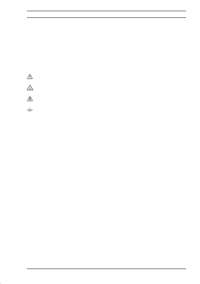
Attention Symbol: Indicates a potentially hazardous condition exists and that it is necessary for the operator
to refer to the instruction manual to ensure the safe operation of this instrument.
Hot Surface Warning: Indicates a hot surface that may be at a temperature capable of causing burns, refer
to the instruction manual for further safety information.
Caution Risk of Electric Shock: Indicates hazardous voltages may be present, refer to the instruction manual
for further safety information.
Protective Conductor Terminal: For protection against electrical shock during a fault condition. This symbol
is used to indicate terminals that must be connected to electrical ground before operating equipment.
Summary of Safety Precautions
The following general safety precautions must be observed while operating or servicing this
instrument. Failure to comply with these precautions may result in personnel injury or death.
Instrument Electrical Earth
This instrument is designed as a Class 1 electrical safety insulation device. To ensure
continued protection from electric shock the instrument chassis must be connected to an
electrical ground. The instrument is supplied with an AC power cable with an earth connection.
Live Circuits Danger
Do not connect the power supply to or operate this instrument with the protective covers
removed. Component replacement and internal adjustments must be made by qualified
service personnel. Do not replace components with the power cable connected. Under certain
conditions, dangerous voltages may exist with the power cable removed. To avoid injuries
always disconnect power and discharge circuits before touching them.
Do Not Modify this Instrument or Substitute Parts
Because of the danger of introducing additional hazards; do not perform any unauthorised
modification or install substitute parts to the instrument. Only fuses with the rated current,
voltage and specified type should be used, failure to do so may cause an electric shock or fire
hazard. Return the instrument to Automatic Systems Laboratories for service and repair to
ensure the safety features are maintained.
Do Not Operate in either Damp or Explosive Environments
This instrument is not designed to operate while wet, in an environment of condensing
humidity or in the presence of flammable gases or vapours. The operation of this instrument
in such an environment constitutes a safety hazard.
Certification
CROPICO certifies that this product met its published specifications at the time of shipment
from our factory. All calibration measurements performed in the manufacture of this instrument
are traceable to the National Physical Laboratory (London).
Assistance
For after sales support and product service assistance please contact CROPICO Customer
Support Group. Contact information is provided in the operation instruction manual.
Page 5

Operating Instructions
Microhmmeter Type DO5000
Table of Contents
1. Introduction 1
1.1 Overview 1
1.2 Definitions and Terminology 2
1.3 Standard Features of the DO5000 3
1.4 Principles of Measurement 4
1.5 Specification 5
1.5.1 Measurement Accuracy 5
1.5.2 Programmable Current 5
1.5.3 Measurement Accuracy with Current Levels 5
1.5.4 Temperature Compensation 5
1.5.5 Conditions of Use 6
1.5.6 Lead Resistance 6
1.5.7 Mains Supply 6
1.5.8 Battery Operation 6
1.5.9 Weight and Size 6
2. Setting up the DO5000 7
2.1 Safety Information 7
2.1.1 Mains Voltage Selection and Changing the Fuse 7
2.2 Unpacking the Instrument 8
3. About the DO5000 9
3.1 The Front Panel 9
3.2 ON/OFF Switch 9
3.3 The Function Keypad 9
3.4 Table Summary of Basic Functions 10
3.5 About the DO5000 Display Screen 12
3.6 About the DO5000 Function Keys 13
4. Setting up measurement options 14
4.1 Range Selection 14
4.2 Current Selection 14
4.3 Measurement Mode 14
4.4 Temperature Compensation 16
4.5 Limits 17
4.6 Data Logging Function 18
4.7 Setup Memory 18
4.8 Display Menu 19
4.9 Measure/Hold Function 20
4.10 Measure Stop Function 20
4.11 Measurement Zero 10
5. Measuring with the DO5000 21
5.1 Connecting to the DO5000 21
5.2 Connecting to the Resistance to be Measured 21
5.3 Lead Connection Types 21
5.4 Resistance Measurement 23
5.5 Resistance Measurement with Temperature Compensation 23
5.6 Resistance Measurement with Limits 24
5.7 Measurement of Inductive Devices 25
6. Accessories 27
6.1 Leads 27
6.2 Wire Clamps 27
6.3 Coin Jigs 27
6.4 Interfaces 27
6.5 Temperature Probe 28
Page 6

Operating Instructions
Microhmmeter Type DO5000
1
1. Introduction
1.1 Overview
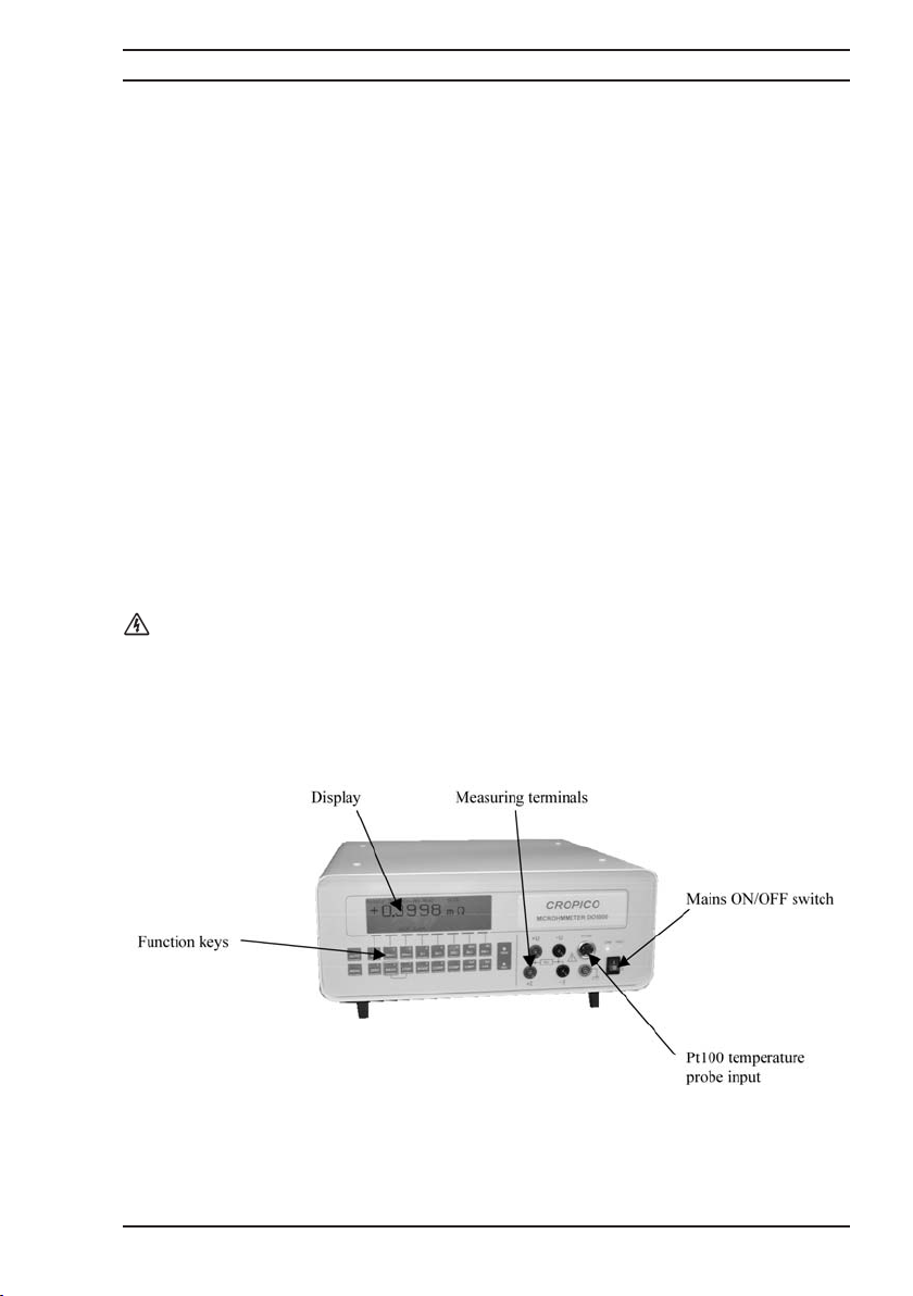
The DO5000 Microhmmeter is a high accuracy instrument designed for industrial and
laboratory resistance measurements.
Features include:
• Programmable measuring current user selectable in 100 steps.
• Automatic temperature Compensation.
• Hi/Lo Limits with red/green front panel warning Pass/Fail lamps.
• Switched current mode with automatic averaging ensures elimination of thermal emf
errors.
• Large graphic LCD display for resistance measurement values as well as configuration
settings and statistical results.
• Advanced functions include data logging and statistical reporting with max/min,
average values peak to peak values and standard deviation.
• Analogue output, IEEE-488 and RS232 communication, and PLC interfaces available
for automated monitoring and controlling applications.
• Fast mode 50 measurements/second for production testing.
The DO5000 is a true four wire measuring instrument eliminating the need to compensate for
lead resistance. The measured value is displayed in large characters with decimal point and
units kΩ, Ω, or mΩ. For maximum accuracy the measuring current may be automatically
reversed and the average of measurement displayed. For measurements on unstable samples,
a rolling average filter is available.
Resistance measurement accuracy is typically 0.03% (1 year specification) and the value may
be displayed with or without temperature compensation, the final accuracy depends upon the
current selected.
The front panel measurement connections are made via 4mm sockets located on the front
panel. The connection to a Pt100 temperature sensor is made with a standard DIN connector.
Page 7

Operating Instructions
Microhmmeter Type DO5000
2
1.2 Definitions and Terminology
µΩmicrohmm 0.000001 Ohm
mΩmilliohm 0.001 Ohm
kΩkilohm 1000 Ohm
Pt100 Platinum resistance thermometer (100Ω at 0°C)
+U/-U Voltage connection
+I/-I Current connection
Four terminal measurement Kelvin principle of measurement using 2 wires (I1 I2) to
pass current through Rx and 2 wires (P1 P2) to measure the
voltage.
Kelvin clips Crocodile clips with isolated jaws, one side being the current
I connection, the other voltage U connection.
Indicates reading compensated for 20°C
Ω/Km Indicates resistance per Kilometre
Km Indicates cable length in Kilometres
m Indicates cable length in metres
TC
:
Page 8
Operating Instructions
Microhmmeter Type DO5000
3
1.3 Standard features of the DO5000 Microhmmeter include:
• Direct display of resistance
• Illuminated display
• Up to 10 Amps measuring current (programmable 10% to 100%)
• Automatic Temperature compensation
• Display hold function
• Display zero function
• 4000 event data logger
• Statistical reporting
• Measuring current reversal with auto average
• Hi/Lo Limits with Red/Green front panel warning LEDs
• Fast measuring mode 50 measurements / second
• General warning symbol. This indicates that a hazardous condition may exist.
You must read the relevant sections in this Operator’s Manual before operating
the instrument.
Page 9

Operating Instructions
Microhmmeter Type DO5000
4
1.4 Principles of measurement
BLANK PAGE
Page 10
Operating Instructions
Microhmmeter Type DO5000
5
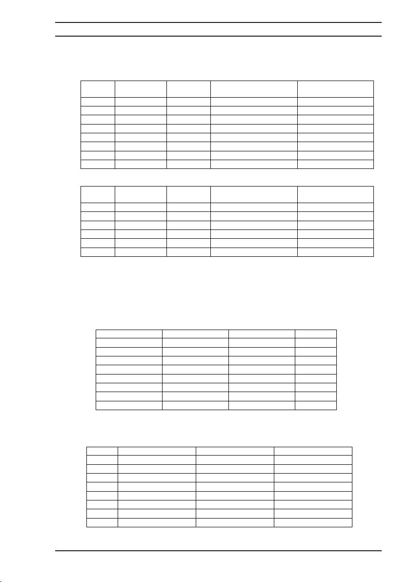
1.5 Specification
1.5.1 Measurement Accuracy
5000/5001
5002
The accuracy is quoted at full rated current with auto average current mode and the display
count is 30,000* plus sign and unit
The 200mΩ range has a scale length of 20,000
1.5.2 Programmable current
The measurement current is adjustable on each resistance range as follows:
The accuracy of current is typically ±0.25%
1.5.3 Accuracy against current level
Range Max. Current Resolution Accuracy at full rated
30 k: 100PA 1:
3 k:
300:
30:
3:
200m:
30m:
3m:
1mA
10mA
100mA
1A
10A
10A
10A
100m:
10m:
1m:
100P:
10P:
1P:
100n:
±(0.03%Rdg+0.02%FS) 10ppm Rdg + 6ppm FS
±(0.03%Rdg+0.01%FS) 10ppm Rdg + 6ppm FS
±(0.03%Rdg+0.01%FS) 10ppm Rdg + 6ppm FS
±(0.03%Rdg+0.01%FS) 10ppm Rdg + 6ppm FS
±(0.03%Rdg+0.01%FS) 10ppm Rdg + 6ppm FS
±(0.03%Rdg+0.01%FS) 20ppm Rdg + 6ppm FS
±(0.03%Rdg+0.01%FS) 30ppm Rdg + 6ppm FS
±(0.03%Rdg+0.02%FS) 30ppm Rdg + 6ppm FS
current
Temp. Coefficient/qC
Range Max. Current Resolution Accuracy at full rated
30 k: 100PA 1:
3 k:
300:
30:
3:
200m:
1mA
10mA
100mA
100mA
100mA
100m:
10m:
1m:
100P:
10P:
±(0.03%Rdg+0.02%FS) 10ppm Rdg + 6ppm FS
±(0.03%Rdg+0.01%FS) 10ppm Rdg + 6ppm FS
±(0.03%Rdg+0.01%FS) 10ppm Rdg + 6ppm FS
±(0.03%Rdg+0.01%FS) 10ppm Rdg + 6ppm FS
±(0.03%Rdg+0.01%FS) 10ppm Rdg + 6ppm FS
±(0.03%Rdg+0.01%FS) 20ppm Rdg + 6ppm FS
current
Temp. Coefficient/qC
Range Max Current Min Current Steps
30 k: 100PA 10PA 1PA
3 k:
300:
30:
3:
200m:
30m:
3m:
1mA
A 1mA
10m
A 10m
100m
1A 100m
10A 1A
10A 1A
10A 1A
100PA 10PA
A 1m
100PA
A 10m
100m
100m
100m
Range 100% Current 50% Current 10% Current
30 k:
3 k:
300:
30:
3:
200m:
300m:
30m:
3m:
±(0.03%Rdg+0.02%FS) ±(0.04%Rdg+0.02%FS) ±(0.06%Rdg+0.02%FS)
±(0.03%Rdg+0.01%FS) ±(0.04%Rdg+0.01%FS) ±(0.05%Rdg+0.01%FS)
±(0.03%Rdg+0.01%FS) ±(0.04%Rdg+0.01%FS) ±(0.05%Rdg+0.01%FS)
±(0.03%Rdg+0.01%FS) ±(0.04%Rdg+0.01%FS) ±(0.05%Rdg+0.01%FS)
±(0.03%Rdg+0.01%FS) ±(0.04%Rdg+0.01%FS) ±(0.06%Rdg+0.01%FS)
±(0.03%Rdg+0.01%FS) ±(0.04%Rdg+0.01%FS) ±(0.06%Rdg+0.01%FS)
±(0.03%Rdg+0.01%FS) ±(0.04%Rdg+0.01%FS) ±(0.06%Rdg+0.01%FS)
±(0.03%Rdg+0.02%FS) ±(0.04%Rdg+0.02%FS) ±(0.06%Rdg+0.02%FS)
A
A
A
A
A
Page 11
Operating Instructions
Microhmmeter Type DO5000
6
1.5.4 Temperature compensation
The accuracy of the temperature measurement is ±0.1% and uses a standard Pt100 sensor.
This accuracy does not include errors due to the sensor itself. The temperature measurement
range is 0…+40°C and the resistance measurement is referenced to 20°C when this option is
used.
1.5.5 Conditions of use
The instrument must be used inside, in a horizontal position
Temperature
Storage: -10°C…+60°C
Operation: 0°C…+45°C
Full accuracy is achieved after 10 minutes warm-up and for a relative humidity <50%
Altitude: up to 2000 metres
Maximum humidity rate: 80% for a temperature of 31°C
1.5.6 Lead resistance
A maximum lead resistance which may be calculated as 0.5Ω/measuring current is permissible
in each of the four measuring leads. The display will indicate if the current lead resistance is
too high.
“**** MEASURENT ERROR Current lead resistance too high ****”
1.5.7 Mains supply
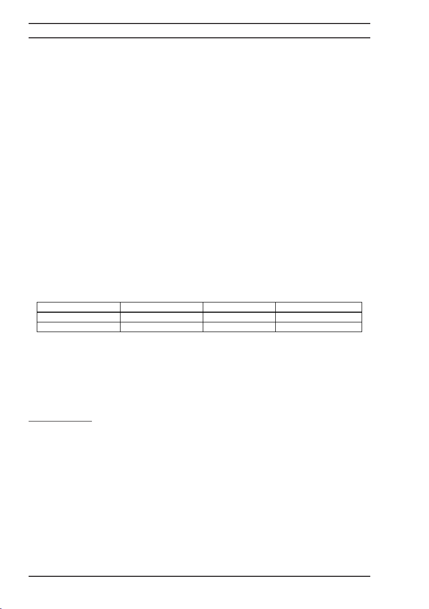
Universal power inlet: Maximum Power consumption 250VA 45/65Hz
1.5.8 Battery Operation DO5001
Two rechargeable sealed lead acid batteries are fitted internally together with the battery
charging circuits. The chargers will maintain the batteries in good condition automatically
adjusting the charge rate to suit the battery state. Full measurement capability is maintained
whilst batteries are charging.
Battery Capacity
Digital: 11 hours continued use with display backlight on
Analogue: Over 6000 simple measurements in fast mode with 10A measuring current.
Approx. 3000 measurements slow mode.
1.5.9 Weight and Size
Size: 147 x 357 x 345 mm (H W D)
Weight: 9.8 kg (DO5000)
12.2 kg (DO5001)
8.15 kg (DO5002)
qq
qq
q
6.3
3.15
Nominal Voltage Voltage Range Frequency Fuse Type
115 V 103…127 V 47…63 Hz 2.5A (T)
230 V 207…253 V 47…63 Hz 1.25A (T)
Page 12
Operating Instructions
Microhmmeter Type DO5000
7
2 Setting up the DO5000
2.1 Safety information
Please read and follow these important safety instructions:
• Read the safety information at the beginning of this manual before operating the
DO5000;
• Make the necessary electrical safety connection checks. In particular, select the
correct line voltage and make sure that the correct fuse is installed. Incorrect voltage
or fuse selections present both an electrical safety and a fire hazard. Ensure that the
rear panel fan is operating and that the vent is not blocked.
• When connecting to an electrical supply mains supply, the mains cord provided with
the equipment should be used, and connected only to a mains supply with a suitable
earth connection. Under no circumstance should the equipment be operated with
earth disconnected.
2.1.1 Mains voltage selection and Changing the fuse
The mains inlet socket is located on the rear panel, to select the correct mains voltage and to
replace the fuse proceed as follows.
• Front panel ON/OFF switch in the OFF position
• Remove the power cord from the inlet socket
• With a small screwdriver, remove the selection sub assembly from the inlet module
• Remove the fuse
• Take off the pale grey plastic piece
• Select voltage: 115 for a 115 volts main and 230 for a 230 volt main
• Replace the grey plastic piece to display the correct voltage in the sub assembly
window
• Replace the correct value fuse according to the table 1.5.7
• Replace the selection sub-assembly in the inlet module
• Connect the power cord
Page 13

Operating Instructions
Microhmmeter Type DO5000
8
2.2 Unpacking the instrument
When you unpack the DO5000, check that the following items are present before starting to
use the unit:
• 1 x DO5000 Microhmmeter
• 1 x Mains Cord
• 1 x Operating Manual
• 1 x Calibration Certificate
• 1 x LS05-P Lead Sets Certificate
Please contact the CROPICO Customer Support Team immediately if any of these items are
missing or damaged.
Please note that we offer a wide selection of measuring leads and test fixtures, see section 6,
please consult our sales staff to order the items most suited to your application.
Page 14
Operating Instructions
Microhmmeter Type DO5000
9
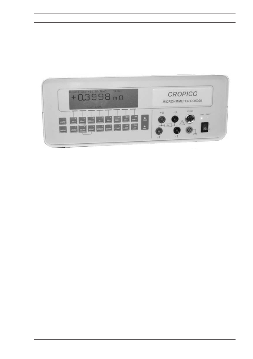
3 About the DO5000
This section introduces you to the features and functions of the DO5000 Microhmmeter.
3.1 The Front Panel
3.2 ON/OFF Switch
The On/Off switch switches the DO5000 on and off. During Power On the last measurement
function setup is restored. The rear mounted cooling fan will always run and the cooling vent
must not be blocked.
3.2.1 ON/OFF Switch Battery Version DO5001
The Front Panel on/off switches the DO5001 on and off. The rear switch situated adjacent to
the inlet filter switches the mains supply on/off.
3.3 The Function Keypad
All DO5000 measurements and programming facilities are accessed through the function
keypad. A brief description of key functions is given in the following table. For a detailed
description of how to use the keys to configure and operate the DO5000, refer to section 4.
Page 15
Operating Instructions
Microhmmeter Type DO5000
10
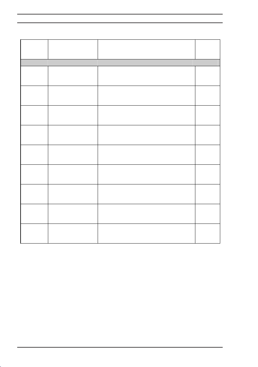
3.4 Table Summary of basic functions
:
:
:
:
:
:
:
:
200
Key
Symbol Description Function
Selection of Range
3m
30m
Selects 3m: range
Selects 30m:
range
300m
Selects 200m:
range
3
30
Selects 3: range
Selects 30: range
300
Selects 300: range
3k
Selects 3k: range
30k
Selects 30k: range
Auto
selects autorange The instrument will select the optimum
Selects and displays the measured value
using the 3m: range
Selects and displays the measured value
using the 30m: range
Selects and displays the measured value
using the 200m: range
Selects and displays the measured value
using the 3: range
Selects and displays the measured value
using the 30: range
Selects and displays the measured value
using the 300: range
Selects and displays the measured value
using the 3k: range
Selects and displays the measured value
using the 30k: range
range required and display the measured
value
Direct
function
or menu
Direct
from
keypad
Direct
from
keypad
Direct
from
keypad
Direct
from
keypad
Direct
from
keypad
Direct
from
keypad
Direct
from
keypad
Direct
from
keypad
Direct
from
keypad
Page 16
Operating Instructions
Microhmmeter Type DO5000
11
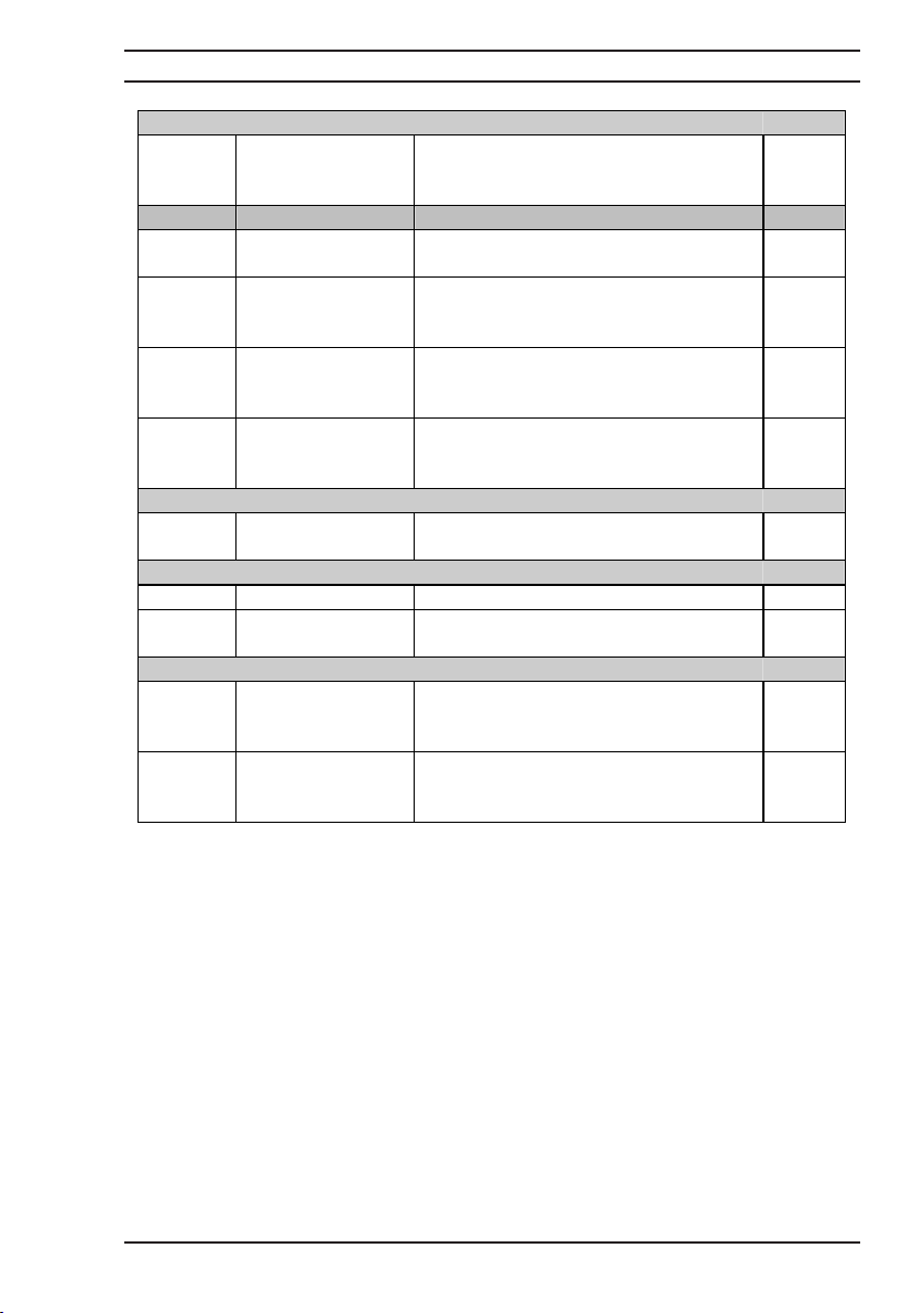
Setting up measurement options
CURR
Current selection Selects the current to be used for
measurement plus single polarity or
switched average
Mode
COMP
Temperature
Selects temperature compensation Menu
compensation
ZERO
MES
Measurement
display zero
function
Measure run/hold Display hold function triggers
Nulls the display at the current reading
and displays measured values relative to
the nulled value
measurement and data logger cycles.
STOP
Measure stop/start Stops the current measurement and
disconnects the measurement current
Logging Data and Statistical Displays
LOG
Data logging
function
Selects the data logging and statistical
analysis menu functions
Options and Configuration
LIMIT
MENU
Limit functions Selects Hi/Lo limit menu Menu
Menu functions Selects interface options and calibration
functions
Scroll and Contrast Control
MENU
Up command key;
Display contrast,
Controls the display contrast and page
scroll functions
page scroll
MENU
Down command
key; Display
Controls the display contrast and page
scroll functions
contrast, page scroll
Menu
Direct
from
keypad
Direct
from
keypad
Direct
from
keypad
Menu
Menu
Menu
Menu
Page 17

Operating Instructions
Microhmmeter Type DO5000
12
3.5 About the DO5000 Display screen
The liquid crystal graphic display clearly indicates the measured resistance and measurement
status as well as displaying available menu options and measurement analysis when selected.
Figure 3.5.1 - Example of Resistance Measurement Mode
The keypad below the display screen controls the DO5000.
Some keys perform a function directly. For example,
selects 3mΩ range.
Other keys switch the display to configuration mode which allows you to select options
through a series of menus.
The option menus all follow the same format. The configuration mode is indicated by splitting
the screen with a dashed line directly below the main reading. An instruction prompt under the
dashed line indicates the current menu. The available menu options are displayed on the
bottom row of the display as shown in figure 3.5.2. Press the corresponding function key to
select an option.
Figure 3.5.2 Example of current mode menu
Indicates current mode Indicates menu options.
The lines printed on the front panel helps you to link the menu option printed on the screen
with the correct key on the keypad.
AUTO1: 30m: 10.0A (AVE) Slow
+ 18.000 m:
Meas Cont
AUTO1: 30m: 10.0A (AVE) Slow
0
3m:
+ 18.000 m:
----------------------------------------------------------------------------------------
Powr
+I -I Ave Mode Mag Quit
Page 18
Operating Instructions
Microhmmeter Type DO5000
13
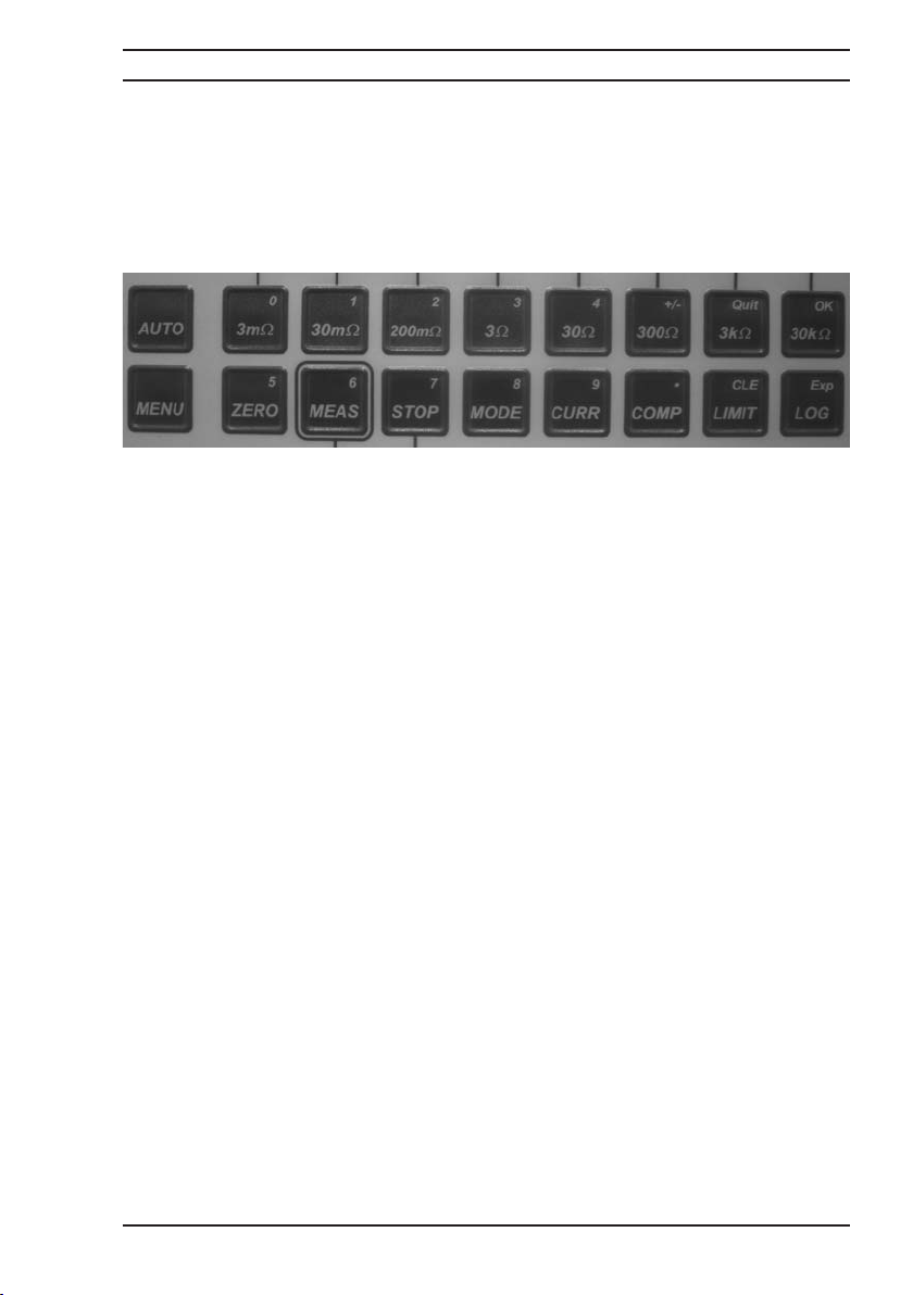
3.6 About the Function keys
The top row of function keys are only used to select menu options. The lower row of function
keys is enabled only when entering values; these instances are covered later in this section.
Both rows of function keys are shown in figure 3.6.1
Figure 3.6.1 - Function keys
The [Quit] and [OK] menu options consistently use the [Quit] and [OK] keys. Use the [Quit] key
to leave a menu or return to the Resistance Measurement mode screen. Use the [OK] key to
confirm a particular choice and continue to the next set of menu options.
Not all function keys are used to access the Configuration Mode. Some just invoke the
function which is printed on the key. For example pressing [ZERO] immediately sets the
measured value displayed to zero.
The rest of this section describes each key in detail and gives examples of how to configure
the measurement to your requirements.
The last used set up conditions are stored when the instrument is turned off and restored
upon switch on.
Page 19
Operating Instructions
Microhmmeter Type DO5000
14
4 Setting up Measurement Options
Note: It is possible to reset the instrument to the original default start up conditions. From the
[MENU] mode press [RESET] to restore defaults.
4.1 Range Selection
Two modes of range selection are possible, Manual and Auto range. The 8 ranges may be
selected individually by pressing the appropriate range key. The range selected is indicated on
the top left hand side of the display. Auto range is selected using [AUTO] key. This key toggles
the selected function as follows; AUTO1 auto ranges starting with the highest range. AUTO2
auto ranges starting with the current range selected; Range manual range is selected.
4.2 Current Selection
Press [CURR] selects the current configuration menu;
Select the current direction +I -I or Ave ; Ave automatically switches the current in the positive
and negative directions and displays the average, this eliminates errors due to thermal emf.
Select the current Magnitude [Mag]. Press [Chng] and you will be asked to enter the maximum
current as a percentage 10…100.
Enter the percentage required using the keys which are numbered in the top right hand corner,
press [OK] to confirm. The current value for the range selected is displayed at the top center
of the screen. The percentage of maximum current set will be applied to all subsequent
measurement ranges selected.
4.3 Measurement Mode
Press [MODE] to select the measurement mode options
For the greatest flexibility and versatility of measurement the DO5000 has many advanced
features which can be selected from this menu.
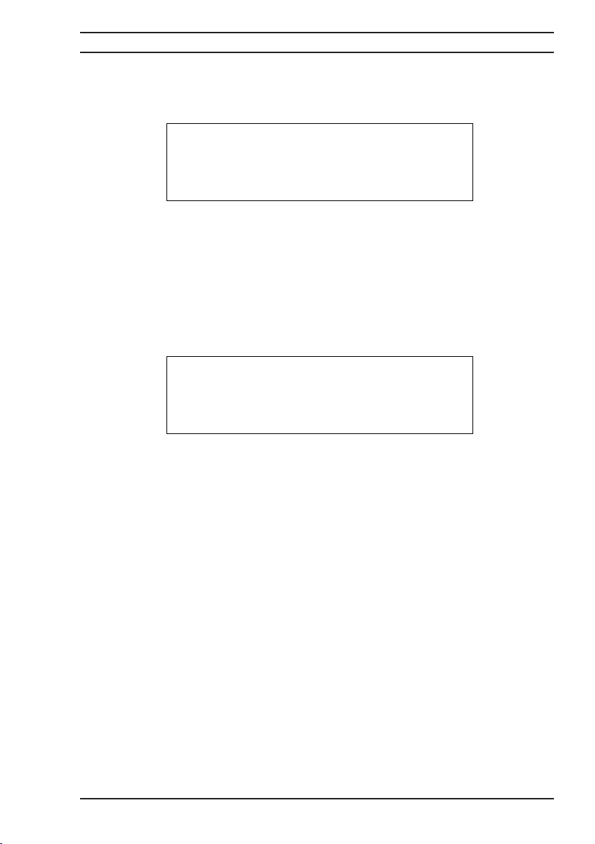
+I -I Ave Mag Quit
Display Trig Read
::/Km Km
Mode Rate Filt Sett Quit
Page 20
Operating Instructions
Microhmmeter Type DO5000
15
Display
The main value display can be set to read Ω, Ω/\km or Km. From the measurement [MODE]
screen select [Ω/Km] this display will read:
Select [No.] Display will ask you to enter the number of conductors 1 – 99, enter the number
and press [OK]. Select [Len] the display will prompt you to enter the cable length [enter value
(Km)]. To select the units to be displayed select [Unit] metre or Km can be selected. Finally,
select [Conn] and the option to select whether the conductors are in series [Ser] or parallel
[Par] is available. Press [OK] to confirm.
Once these parameters are set the measured value will display in Ω/Km for any number of
conductors 1 – 99 in series or parallel.
To display the cable length in Km select [MODE], [Km], the display reads:
To change the number of conductors select [No.] the display will ask you to enter the number
1 – 99. Enter the number and press [OK]. Select [Res] and you will be prompted to enter the
resistance of the cable in ohm/Km, enter the value and press [OK]. To change the units press
[Unit] you can now select [Km] or [m]. Press [OK] to confirm selection. To change the
connection configuration select [Conn] and the option to select the conductors in series or
parallel, again press [OK] to confirm. Once the configuration is complete, press [Quit] to return
to the measurement screen which will display the measured cable length in Km or m.
Press [Trig Mode]. To select continuous measurement press (Cont) or (Sing) to select a single
measurement, this completes one measurement and holds the value on the display. To trigger
a new measurement the direct function key [MEAS] should be pressed.
Press [Read Rate] to select (Fast) or (Slow) measurement mode. With Fast mode selected the
DO5000 will measure at 50 measurements per second. This mode is intended for automatic
measurements using one of the interfaces to output the measured values or control an external
process. The measured value will be displayed in small text on the screen when Fast
measurement mode is used.
1 cable of 1Km in series
Change:
No. Len Unit Conn Quit OK
1 cable of 1Km in series
Change:
No. Len Unit Conn
Page 21

Operating Instructions
Microhmmeter Type DO5000
16
For manual operation the Slow measurement mode should be selected. This will read at 2
measurements per second and offer the highest accuracy and resolution.
Press [Filt] to select the digital filter, this feature should be used when the sample to be
measured is unstable and the measured value displayed is constantly changing. The filter is a
rolling average of n measurements where n may be set between 1 and 32.
Press [Sett] to select the setting time filter; this would normally be used when measuring
inductive samples such as motor winding resistance.
Press [Limit] to set maximum number of permissible digits 1-999 that the reading can change.
Press [No of readings] to select the number of readings 2-999 that the set limit must conform
to.
4.4 Temperature Compensation
Press [Mode] to select the setup menu for temperature compensation
Press [Ext] to select the external temperature sensor.
Press [Man] to select the manual compensation temperature, the display will request that you
enter the ambient reference temperature.
Press [Cu] to select compensation for copper 3930 ppm/°C
Press [Al] to select compensation for Aluminum 4100 ppm/°C
Press [Usr] to enter alternative user coefficients
The equation used to calculate the corrected resistance is:
Rc (20°C) = Rx/1+ (tx - 20°C)
where Rc = resistance corrected for a reference temperature 20°C
} = Average temperature coefficient
tx = Component temperature at time of the measurement
The temperature compensation mode should be used when measurements are required to be
referenced to 20°C. This is particularly useful when measuring materials with a high
temperature coefficient such as copper, as the ambient temperature varies so will the
resistance value being measured. Using the temperature compensation mode references all
values back to a temperature of 20°C.
The compensated resistance value measured will be displayed in large digits in the centre of
the display and the true resistance will be displayed in smaller text below. The ohms sign of
the compensated value will show a 20 in the centre to indicate that the value is referenced to
20°C.
Page 22
Operating Instructions
Microhmmeter Type DO5000
17
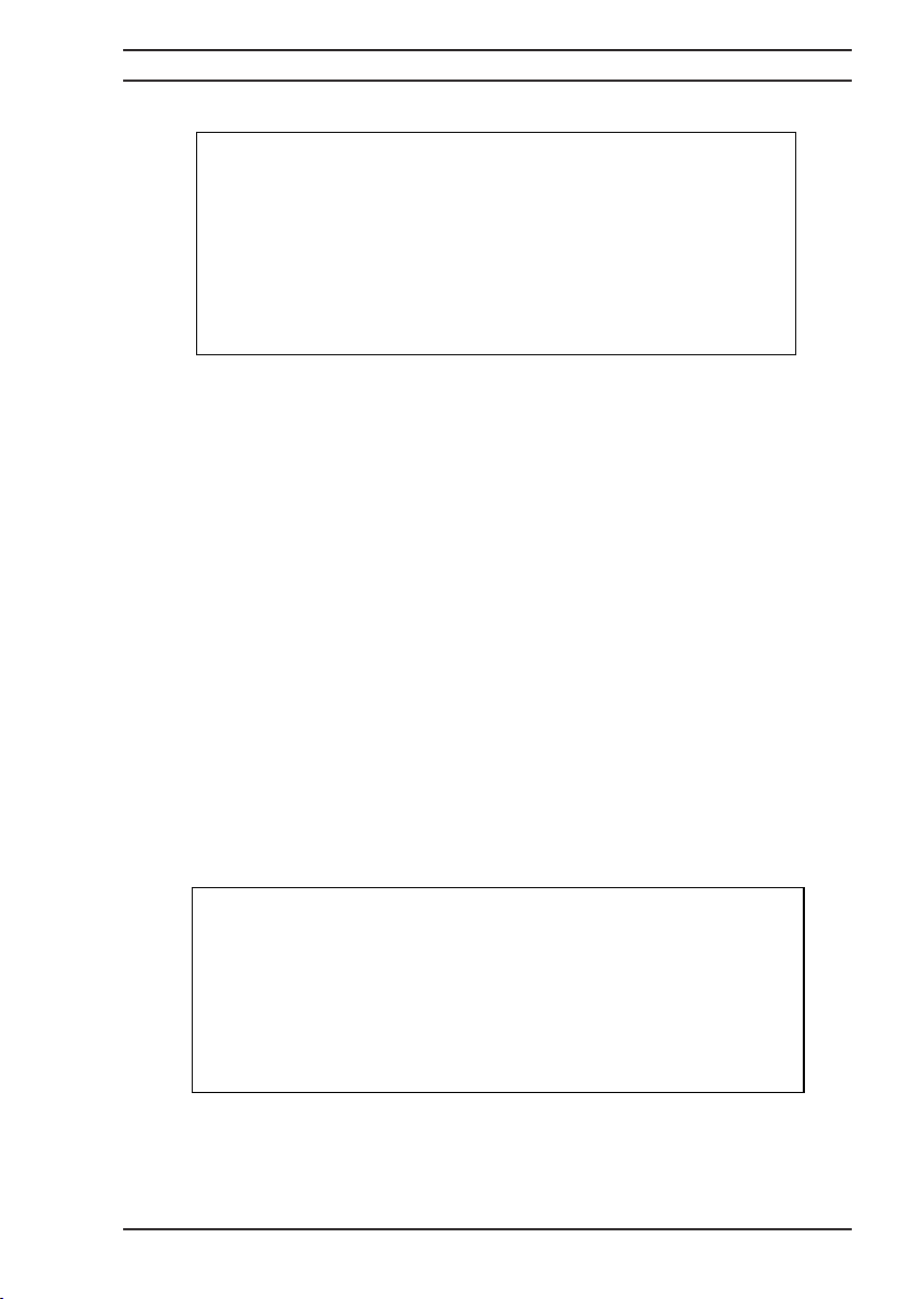
Figure 4.4.1 Measurement screen with temperature compensation
4.5 Limits
Press [Lim] To select the Limits menu.
Two options are then available [Meas] which enables limits to be set with reference to the
measured values or [O/C] which enables the open circuit voltage to be limited to either 20mV
or 50 mV. Note: Open circuit limits are not available on 3K x 30K ranges.
Select [Meas] to select the measurement limits menu.
Select [Alm] to turn the audio alarm (Beeper) on or off.
Select [Max] to set the max or upper limit value press [Chg] and the screen will prompt you to
select the units mΩ…Ω…kΩ. Select the required units and the display will ask for a new max
limit value to be entered. Use the numbered keypad to enter the required limit, press [OK] to
confirm.
Select [Min] to set Min or lower limit value, proceed as for setting max limit.
The Green Pass front panel LED will light when the measured value is correct and within the
set limits, the Red Fail LED will light and the warning beeper will sound if the measured value
is higher than the Max limit set or lower than the Min limit set. The DO5000 screen will also
display PASS or FAILED with >> to show value to high and << to show value to low.
Figure 4.5.1 Measurement screen with limits
To select the open circuit voltage limit from the [Lim] menu select [O/C] the option of selecting
either 20mV of 50mV limit is then available. The measurement display will indicate in the top
right hand corner which limit has been set.
AUTO1: 30m: 10.0A (AVE) Slow
TC
+ 18.000 m:
T= + 22.00qC (Ext) RX = 18.010 m: (Cu)
Meas Cont
AUTO1:
30m: 10.0A (AVE)
+ 18.000
----------------------------------------------------------------------------------------
<<FAILED<<
Meas Cont
Slow
m:
Page 23

Operating Instructions
Microhmmeter Type DO5000
18
4.6 Data Logging Function
Press [LOG] to select the data logging menu
Select [New] to initiate a new log the screen will prompt you to clear the current log. Press
[Yes] the screen will ask you confirm, press yes again and the current log will be cleared of all
stored values. You are now ready to set up the new log.
Press [No. Rdgs] the current number of readings is displayed to accept that value press [Yes]
to store a different number press [No] you will then be asked to enter the value of the number
of readings to be stored in the log. Enter the number required between 1 and 4000 and press
[OK]. Press [Rev] to review the current readings stored in the log these will be displayed in
table form as shown in Figure 4.6.1
Figure 4.6.1 Data Logging Screen
Once the logging mode has been switched ON the measurement display will be in HOLD mode
and the bottom line of information text will show the total number of samples to be stored and
the number of measurements already stored. (Samples = 40/40). To start the logging press the
[MES] key the measurements will start and the values stored. Once the set number of values
has been stored in the log the measurements will be stopped.
Press [Stats] to display the statistical analysis of the values stored in the log. The following
values will be computed and displayed.
Minimum value [Min] Maximum value [Max]
Mean value [Mean] Peak to Peak value [PtP]
Standard Deviation [SD]
4.7 Setup Memory
To enable up to 10 measurement configurations to be setup and stored the DO5000 has 10
memories to store and recall these configurations;Press [MENU]
Press [Mem] to select memory menu
Press [STOR] to store the current measurement setup you will be prompted to enter a memory
store number 0 to 9, selecting the store number saves the current setup to that store number
Press [RCL] to recall a previously stored setup you will be prompted to enter the memory store
number that you wish to recall, entering that store number recalls the stored configuration for
immediate use.
Press [List] to display a list of memories in current use
Press [CLR] to clear a previously stored configuration you will be prompted to enter the store
number , entering the number will erase the stored parameters from that memory.
Log # Range Resistance Date Time
1
2
3
4
5
6
30k:
30k:
30k:
30k:
30k:
30k:
0.000 10/08/99 14:10:35
0.000 10/08/99 14:10:37
0.000 10/08/99 14:10:38
0.000 10/08/99 14:10:40
0.000 10/08/99 14:10:42
0.000 10/08/99 14:10:44
Page 24

Operating Instructions
Microhmmeter Type DO5000
19
The following parameters will be stored when saved to memory:-
PARAMETER DEFAULT VALUE
Range 30kOhm range
Auto-range on - auto 1
Current direction positive
Current Magnitude 100%
Current mode DC
Trigger mode continuous
Reading rate slow
Temperature compensation off
Temperature compensation mode manual
Temperature compensation material copper
Manual compensation temperature 20∞C
Filter off
Filter - No of readings 10
Measurement limits off
Measurement limits alarm on
Measurement limit - maximum 30 kOhm
Measurement limit - minimum 0
Open circuit limit off
Log mode off
Log mode - No. of readings stored 10
4.8 Display Menu
Press [MENU] to select the display menu
Press [RESET] to reset measurement configuration to default values.
Press [MEM] to select memory menu
Press [LCD] to select LCD display menu, Press to turn backlight ON or OFF, Press and
hold [ [] ] to lighten then display contrast, Press and hold [ ® ] to darken the display contrast.
Press [Set Up] to select the configuration menu. [Beep] turns the beeper on and off, [Time
Date] enables the current time and date to be set, [Lang] enables the display to be toggled
between English and French language, [Temp Unit] permits the temperature units to be
switched between ˚C and ˚F, [Line Freq] allows the measurements to be synchronized at 50Hz
or 60Hz and should be set in accordance with mains supply frequency used, this is particularly
important when measuring in fast mode. Press [Ver] to display the model number and software
version.
Press [Rem I/F] to select the remote interface option menu
Press [Key Lock] to select the option of locking the keyboard to ensure no parameters are
changed without authorisation. You will be asked to enter a pass code before you can enter
this menu. The default pass code is 9252 and this can be changed once you have entered the
Key Lock menu. Three options are available [ALL] enables all keys and permits normal control
of the DO5000. [MEM] permits operation of the Memory, Recall, and Measure Keys only.
[Measure] restricts operation to the Measure Key only. Once the Key Lock facility is enabled
the measurement screen will display a small padlock symbol in the bottom right hand corner.
[ ]
Page 25

Operating Instructions
Microhmmeter Type DO5000
20
4.9 Measure/Hold function
Press [Mes] to hold the measured value on the display. NOTE this does not interrupt the
measuring current which will still be flowing through the resistance being measured.
WARNING when measuring with 10 Amps measuring current, it is possible to produce small
sparks at the current terminals. Press [Mes] to resume display of measured values.
4.10 Measure Stop Function
Press [STOP] to stop the measurement this disconnects the current from the terminals and
internally shorts the current terminals discharging any voltage that may be stored in capacitive
samples.
4.11 ZERO Function
Press [ZERO] to null the current display reading to zero, all subsequent measurements will be
relative to the nulled value. Pressing [ZERO] again cancels the zero. Changing range or
selecting auto range also cancels the zero.
Page 26
Operating Instructions
Microhmmeter Type DO5000
21
5 Measuring with the DO5000
5.1 Connecting to the DO5000
The DO5000 uses a four terminal method of measurement which eliminates errors due to lead
resistance. The measuring leads plug into the four front panel safety sockets. The sockets are
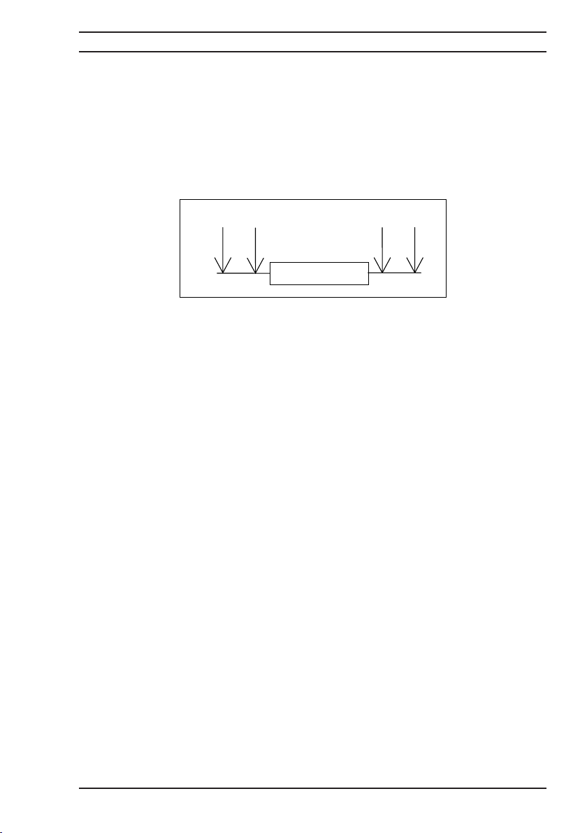
marked +U, -U, +I, & -I. Connections to the resistance to be measured should be as per Figure
5.1.1
Figure 5.1.1 Connection diagram
NOTE: It is important to connect the I (current) leads outside the U (potential) leads
5.2 Connecting to the resistance
The Digital Microhmmeter DO5000 employs a four wire method of measurement, i.e. it is
necessary to make four connections to the resistance under test. The instrument is supplied
with four leads; two for the potential connections which are made across the test resistor at
the points between which the resistance is to be determined; and two for the current
connections which connect the test resistor to the current supply circuit.
5.2.1 Connect the red leads to the +U and +I sockets and the black leads to the -U and -I
sockets.
5.2.2 Connect to the resistance under test as shown in figure 5.1.1, Cleanliness is important
and if the sample is not clean, a rub with an abrasive paper to remove oxides is recommended.
5.3 It is not always possible to use the combined current and potential crocodile clips (Kelvin
clips), in which case test leads with spade tags, or special fixtures may have to be made to
suit the particular application. We offer a variety of different lead and fixture types which are
list in section 6.1
+U
+I
Rx
-U
-I
Page 27
Operating Instructions
Microhmmeter Type DO5000
22
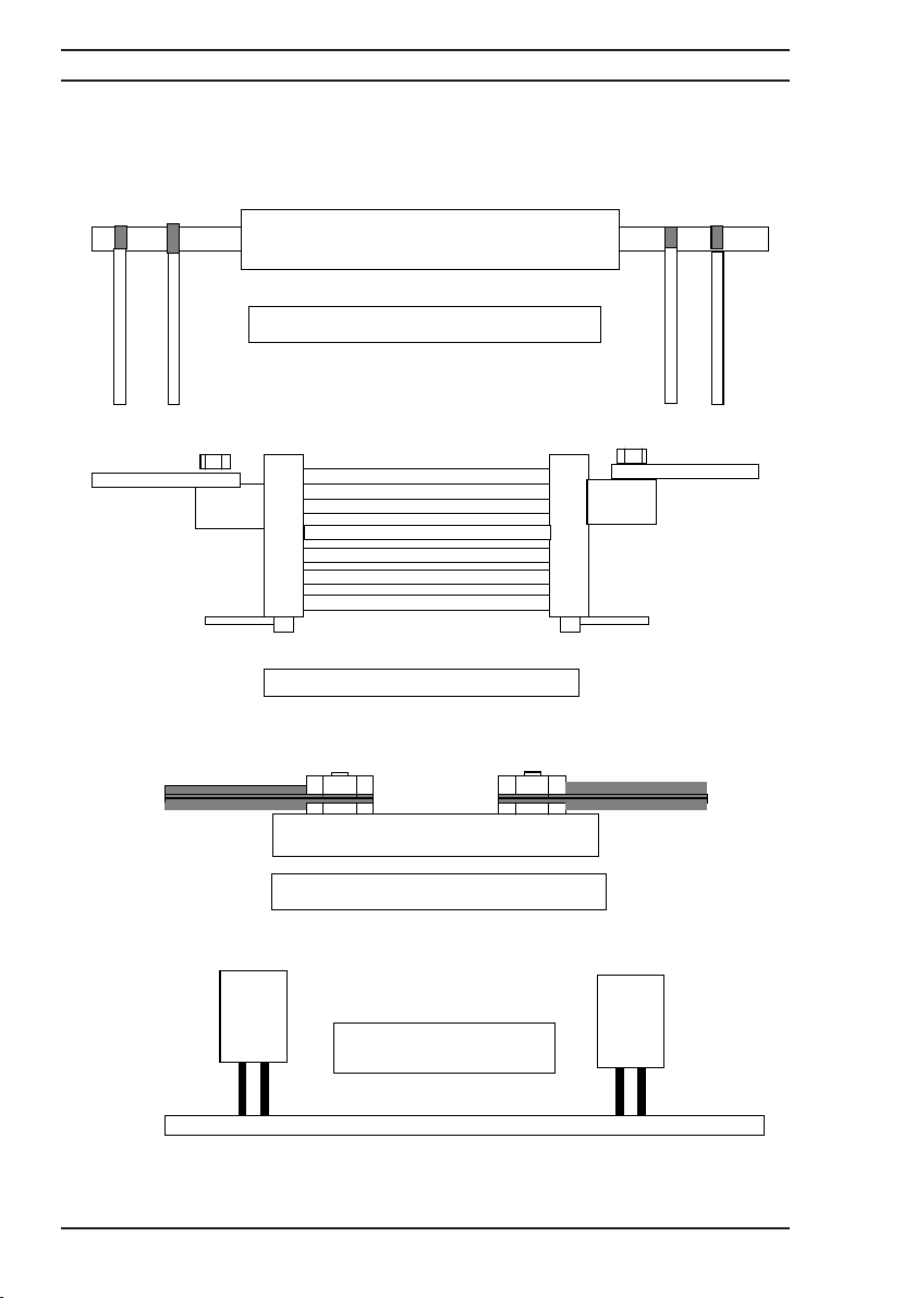
Figure 5.3.1 Diagram of different connection configurations
C1 P1 P2 C2
Connection to Cable Joint
C1
C1
P1 P2
C1 P1
C2
P1 P2
Connections to Current Shunt
C2
Connections to Stud Terminals
Measurement with duplex
handspikes
P2 C2
Page 28
Operating Instructions
Microhmmeter Type DO5000
23
5.4 Resistance measurement
The DO5000 should be in the measurement [STOP] mode. In this mode the measuring current
is switched off and the current terminals are shorted internally. Connect the measuring leads
as described in section 5.3 before starting the measurement select the current level and mode
required as described in section 4.2 WARNING the maximum measuring current is 10 Amps
on the lowest 3 measuring ranges ensure that the current level selected will not damage the
resistance being measured. Select the range required see 4.1 or auto range.
To start the measurement press the [MEAS] button the measured resistance value will be
displayed on the screen.
5.5 Resistance measurement with temperature compensation
Temperature compensation should be used when measuring the resistance of materials which
have a high temperature coefficient. Copper, for example, has a temperature coefficient of
0.3980%/K. The value of the resistance measured will therefore vary with the temperature of
the copper. To obtain consistent and meaningful results, the resistance values may be related
to a set ambient temperature, normally 20°C.
Example: Copper with a temperature coefficient of 3980ppm/k = 0.3980%/k
To measure with the temperature compensation, proceed as in 4.4 but in addition connect the
temperature sensor probe (see section 6 for accessories details and part numbers) to the front
panel socket. Select the temperature compensation measurement mode as described in 4.4.
Alternatively, if the ambient temperature is stable, a manual value may be entered, in this case
a temperature sensor is not required. The true measured resistance value will be displayed in
large digits on the DO5000 screen and the compensated value will be shown in smaller digits
below the main display. The measured or set temperature will also be shown.
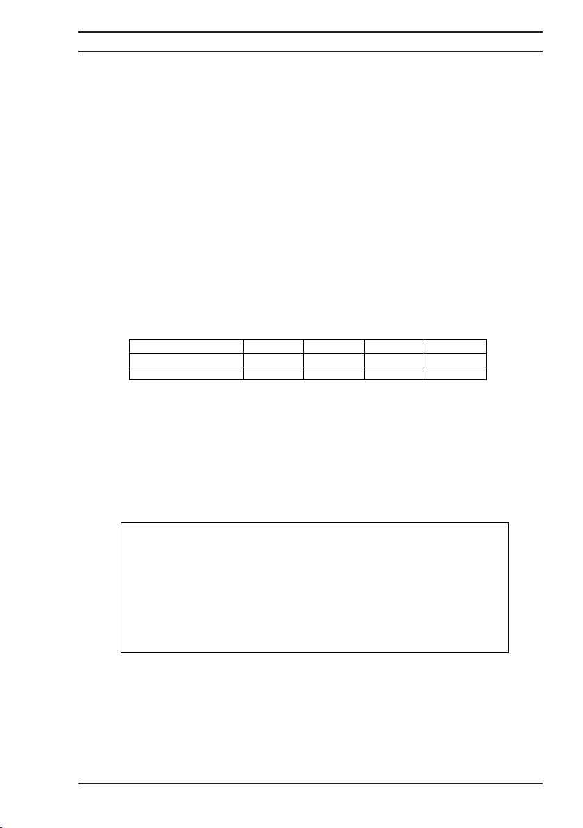
Figure 5.5.1 Display screen temperature compensation mode
Temperature
Resistance of Copper
% Increase in resistance 0% 1.99% 3.98% 5.97%
AUTO1:
+ 18.358
T = + 25.00qC (Ext)
Meas Cont
20qC 25qC 30qC 35qC
18.000 m: 18.358 m: 18.716 m: 19.075 m:
30m: 10.0A (AVE)
Slow
m:
RX =
18.000 m: (Cu)
TC
Page 29
Operating Instructions
Microhmmeter Type DO5000
24
5.6 Measurement with Limits
The measurement limits function permits the fast easy sorting of components.To select the
limits function see section 4.5. Both high and low limit values may be set.If the measured value
is within the set limit boundaries then front panel green PASS LED will illuminate. If the
measured value falls outside the set limits then the red FAIL LED will light, a warning beeper
will also sound and the instrument display will show FAILED with chevron arrows pointing to
the left for value to low and to the right for value to high.
Figure 5.6.1 Measurement display with limits value to low
Figure 5.6.2 Measurement display with limits value to high
AUTO1: 30m: 10.0A (AVE) Slow
+ 18.000 m:
----------------------------------------------------------------------------------------
<<FAILED<<
Meas Cont
AUTO1: 30m: 10.0A (AVE) Slow
+ 18.000 m:
----------------------------------------------------------------------------------------
>>FAILED>>
Meas Cont
Page 30

Operating Instructions
Microhmmeter Type DO5000
25
5.7 Measurement of Inductive Devices
GENERAL
When the Settling algorithm is selected, and the ‘MEAS’ button pressed, continuous
measurements will be made until two consecutive results are within the selected limit, or until
the selected maximum number of measurements has been reached. In the first case, the final
result will be displayed, and in the second case, the message: “MEASURMENT ERROR –
Failed to Settle” will be displayed. If appropriate, the result (or the ‘error value’) will also be
datalogged, sent out on the bus, and sent to the Analogue Output on the PLC card. Finally, if
the Measurement Limits facility is selected, then the PASS/FAIL result will be displayed.
The Settling facility can be used in ‘SLOW’ mode only.
Normally, the Settling facility should be used in ‘SINGLE’ trigger mode, and the above
description assumes this. However, if ‘CONTINUOUS’ trigger mode is used, then the operation
is the same, except that once the measurement has settled, the settling facility is effectively
disabled, and the DO5000 continues to take measurements without interrupting the current,
until ‘STOP’ is pressed. When ‘MEAS’ is pressed again, the Settling facility will be re-engaged.
MENU ACCESS
The menu is accessed by pressing ‘MODE’, followed by ‘Sett’. From this point, the following
parameters can be set:
On/Off: Selects/Deselects the Settling Algorithm
No. Rdgs: Selects the maximum number of readings to be taken (2 – 999).
This will give a maximum measurement time of approximately 8 minutes.
Limit: Selects the maximum number of display digits by which the two consecutive
readings may differ, for the measurement to be defined as ‘settled’ (1 – 999).
When the facility is selected, the word ‘Sett:xxx’ will appear in the top right corner of the
screen. ‘xxx’ shows the maximum number of readings to be taken, but during a measurement,
it counts the number of readings taken when the measurement settled. (‘Sett:’ will flash during
measurement.)
Note that if ‘CONTINUOUS’ trigger mode is used, then the counter will freeze at the number
when the measurement settled, even though measurements will continue.
EFFECT ON OTHER PARAMETERS
• Selecting the Settling facility will:
• Cause the Autorange to change range in a downward direction only.
(Therefore, only ‘Auto1’ autorange mode should normally be used.)
• Deselect the Filter facility.
• Change Average current mode to Positive current mode.
• Cause an error message if in Fast mode.
PARAMETERS WHICH WILL DESELECT THE SETTLING FACILITY
• The Settling facility will be deselected if:
• Filter facility is selected.
• Average current mode is selected.
• Fast mode is selected.
REMOTE COMMANDS
See attached extract from the Remote Interface Manual for details, and an example
programme.
Page 31

Operating Instructions
Microhmmeter Type DO5000
26
OTHER ISSUES
Due to inductive effects, ‘Overange Error’, ‘Polarity Error’, ‘Excess Resistance in Current Leads
Error’ and ‘Open Circuit Error’ will all be ignored until the final measurement.
If the Autorange changes the range during a measurement, then the ‘Number of Readings’
counter will reset to one.
If the measurement does not settle within the maximum number of readings, then the
‘Resistance’ bit (Bit 9) of the Questionable Data Condition/Event Registers will be set.
When in Manual mode, a short beep will be heard when the measurement is completed, or a
longer beep if the measurement failed to settle.
Page 32
Operating Instructions
Microhmmeter Type DO5000
27
6 Accessories
6.1 Leads
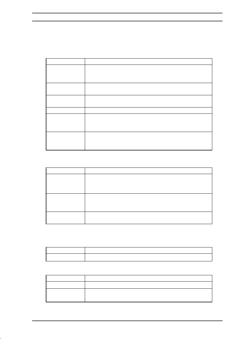
The DO5000 may be used with a variety of lead sets. The following are the available selection.
Remember, if you do not see suitable leads for your application, please consult our customer
help desk.
6.2 Wire Clamps
For the precise measurement of 1 meter cable samples we offer 2 wire clamp options.
6.3 Coin Jig
For the measurement of bi-metal coins to ensure the resistance of the two metals is within pre
defined limits.
6.4 Interfaces for the Remote Control of DO5000
Ordering Code Description
HS01-P Duplex Handspikes with 2.5 metre lead length, current and
potential spikes suitable for plate or Bussbar
measurements.
HS02-P Duplex Handspikes as a HS01-P but with 2.5 and 15 metre
lead lengths
LS03-P Large Kelvin clips with 3 metre lead length suitable for
attaching to rods bars or cables up to 38mm diameter
LS04-P As LS03-P but with lead lengths 3 and 15 metres
LS05 Executive lead set consisting of 4 x 1 metre leads with
banana plugs, 4 x crocodile clips 4 x test prods and 4 x
Kelvin clips (KC1) jaw opening 4mm
LS06-P Kelvin lead set comprising of miniature Kelvin clips (KC2)
with 1 meter leads attached terminated with banana plugs
Jaw opening 6mm. Suitable for fine wires.
Ordering Code Description
C02 1 metre wire clamp with metal base and provision for
temperature sensor suitable for wire cross section 1 to
2
100mm
C02a 1 metre wire clamp with metal base and provision for
temperature sensor suitable for wire cross section 0 to
1000mm
2
CO3 1 metre wire clamp with water bath for the precise
measurement of 1 meter cable samples 1 to 1000mm
Ordering Code Description
CJ01 COIN JIG will accept all bi-Metal Coins
Ordering Code Description
DO5000-GPIB Talk/Listen IEEE-488 Interface
DO5000-PLC PLC Interface includes Analogue Output and Potential free
Contacts for Hi/Lo limits
Page 33
Operating Instructions
Microhmmeter Type DO5000
28
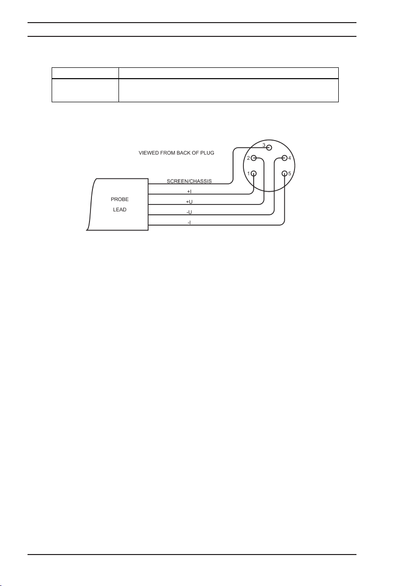
6.5 Temperature Probe
For the sensing of the temperature of the sample under test.
Ordering Code Description
5000-Pt100 Pt100 Temperature Sensor Probe length 200mm, diameter
6mm. Fitted with 1 Metre Lead and DIN Plug
Page 34
Operating Instructions
Microhmmeter Type DO5000
29
For Service and Calibration Contact:
GROUP
CROPICO is a division of
SEAWARD
99 Washington Street
Melrose, MA 02176
Phone 781-665-1400
Toll Free 1-800-517-8431
Visit us at www.TestEquipmentDepot.com
Page 35

Operating Instructions
Microhmmeter Type DO5000
30
Additional Products From Cropico
DIGITAL OHMMETERS
RESISTANCE BRIDGES
RESISTANCE DECADE BOXES
RESISTANCE STANDARDS
DIGITAL THERMOMETERS
THERMOCOUPLE SIMULATORS
PT100 SIMULATORS
INSULATION TEST SETS
UNIVERSAL CALIBRATORS
HIPOT TESTERS
ELECTRICAL SAFETY TESTERS
Phone, fax or e-mail for further information on the above or for a
copy of our general catalogue: - Phone: - +44 (0) 191 5863511
Fax: - +44 (0) 191 5860227
E-mail:- [email protected]
Website: - www.cropico.com
Page 36

610018 Rev 11
 Loading...