

Page 1

DIGITAL
OHMMETER
TYPE DO4A
Page 2

DO4A Issue 3/2001
2
CONTENTS
Page
1. Safety 3
2. Introduction 4
3. Measuring Principle 5
4. Case Design 5
5. Maintenance 5
6. Battery Charging 6
7. Technical Data 7
8. Description of Controls 8
8.1 Auto Zero 8
9. Methods of Measurement 9
9.1 Ohmmeter Connections 9
10. Power-up 12
11. Measurement 12
12. Protection 13
13. Calibration Process 13
14. Accessories 14
Page 3

DO4A Issue 3/2001
3
IMPORTANT NOTE
====================
Instruments are delivered ready for immediate use; no extras are required.
Supplied Accessories: One set of test leads
One mains cord
One copy of Operating Instructions (English)
When unpacked, inspect for physical damage and report any defects
immediately in writing, retaining packaging materials for inspection. Before
placing into service, ensure mains voltage is correct, instruments are normally
supplied for 240V 50Hz. Other voltages may also be selected according to
the chart in section 5, (Maintenance). Be sure to also change the fuse to the
correct type.
1. Safety
Digital Ohmmeter type D04A is designated Safety Class I as defined in the
EN61010.
This apparatus has been designed and tested in accordance with EN61010,
Safety Requirements for Electronic Measuring Apparatus, and has been
supplied in a safe condition. The present instruction manual contains some
information and warnings that have to be followed by the user to ensure safe
operation and to retain the apparatus in safe condition.
If this apparatus is to be connected to a fixed installation, before any other
connection is made, the protective earth terminal shall be connected to a
protective conductor.
Before switching on the apparatus, make sure that it is set to the voltage of the
power supply. The mains plug shall only be inserted in a socket outlet
provided with protective earth contact. The protective action must not be
negated by the use of an extension lead without a protective conductor.
Page 4

DO4A Issue 3/2001
4
WARNING!
Any interruption of the protective conductor inside or outside the apparatus, or
disconnection of the protective earth terminal is likely to make the apparatus
dangerous. Intentional interruption is prohibited.
When the apparatus is connected to its mains supply, terminals may be live, and the
opening of covers or removal of parts (except those to which access can be gained by
hand) is likely to expose live parts.
The apparatus shall be disconnected from all voltage sources before it is opened for
any adjustment, replacement maintenance or repair.
Any adjustment, maintenance and repair of the opened apparatus under voltage shall
be avoided as far as possible, and, if inevitable, shall be carried out only by a skilled
person who is aware of the hazard involved
Make sure that only fuses with the required rate current and of the specified type are
used for replacement. The use of makeshift fuses, and the short-circuiting of fuse
holders are prohibited.
Whenever it is likely that the protection has been impaired, the apparatus shall be
made inoperative and be secured against any unintended operation and returned to
our factory or Agent for rectification.
2. Introduction
The DO4A is an accurate bench/portable digital ohmmeter for the measurement of
resistance in the range 10µΩ to 4000Ω. It offers you the four terminal resistance
measurement method to eliminate the effect of lead resistance. The measured values
are displayed on a 4 digit LCD display; an overflow of the selected range is also
indicated.
Display range 4000
Simple push button selection of the range required ensures the DO4A may be easily
used by unskilled personnel, error and status warnings are illuminated when
appropriate. The utmost care has been used to ensure that the ohmmeter will
withstand an accidental mains voltage applied to the measuring terminals, but it is not
recommended that voltage should be applied.
Page 5
DO4A Issue 3/2001
5
3. Measuring Principle
The measurement is true 4 terminal, using the Kelvin principle. A stable current is
produced across the resistance to be measured via the C terminals, and the voltage
drop across the Rx is measured at the P terminals. This potential drop is then
compared against the voltage drop across internal standards, the ratio of these is then
converted to the resistance value of Rx and displayed in ohms on the digital display.
High accuracy and long term stability is achieved by using our own manufactured
internal resistance standards.
4. Case Design
The case is ruggedly constructed and is a painted aluminium shell with a strong
internal sub-frame. The front panel is a reverse printed polycarbonate overlay with
clear and unambiguous text. The case is painted anthracite grey, and the tilt handle
means that the instrument can be positioned for easy viewing.
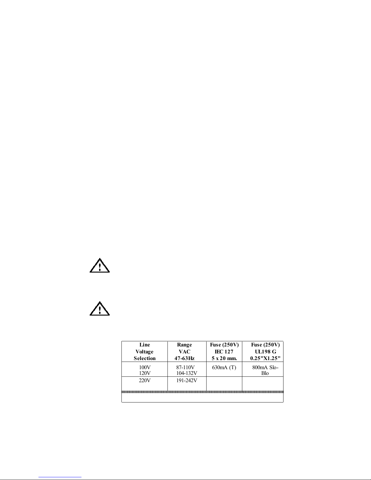
5. Maintenance
Normally no maintenance is required other than cleaning with a moist cloth. Avoid
aggressive detergents or solvents.
CAUTION: Before any maintenance, repair or exchange of parts or
fuses, the instrument must be disconnected from the mains supply and all
power sources. In the event of a fault occurring, the instrument should be
returned to our factory or Agent. A mains fuse is fitted to the mains inlet
socket on the rear panel, and should be replaced if necessary.
CAUTION: Disconnect mains lead and all connecting leads, before
removing fuse holder. Replace only with correct fuse type ie. according
to
the following chart
Line Range Fuse (250V) Fuse (250V)
Voltage VAC IEC 127 UL198 G
Selection 47-63Hz 5 x 20 mm. 0.25"X1.25"
100V 87-110V 630mA (T) 800mA Slo 120V 104-132V Blo
220V 191-242V 315mA (T) 400mA Slo 240V 209-264V Blo
Maximum Input Power : 20VA
Page 6

DO4A Issue 3/2001
6
The input circuits are protected by a 2 AMP fuse located on a holder on the main
printed circuit board. Access is gained by removing the top cover. Only replace with
the correct fuse type as below.
2A 550V rms Type A1
BS 88 : PART 2
!
6. Battery Charging
The DO4A has a built-in sealed lead acid battery, which is fully charged when
delivered. This type of battery has advantages over other types of rechargeable
batteries; it is more tolerant to erratic charging cycles thus giving a better service life.
The battery charger is built in and the instrument may be connected to 100/120/220
or 240 volts supply. The appropriate voltage setting must be selected on the inlet
socket and the correct fuse inserted. The LINE LED will illuminate on the front
panel to indicate when the mains supply is connected.
Charging is automatically controlled with built-in protection circuits eliminating the
possibility of over-charging or deep discharging the battery. The display will flash
8888 when the battery requires recharging. The DO4A will operate at full accuracy
whilst charging and therefore can be used whilst permanently connected to the mains
supply
Battery
The internal battery is a sealed lead acid type. Care should be taken when disposing
of it and it may be returned to Cropico for safe disposal.
Any regulations and directions applying to the disposal of such material must be
applied.
Do not dispose of battery in fire.
Do not short circuit
Do not crush, puncture, open, dismantle or otherwise mechanically interfere with the
battery.
Page 7
DO4A Issue 3/2001
7
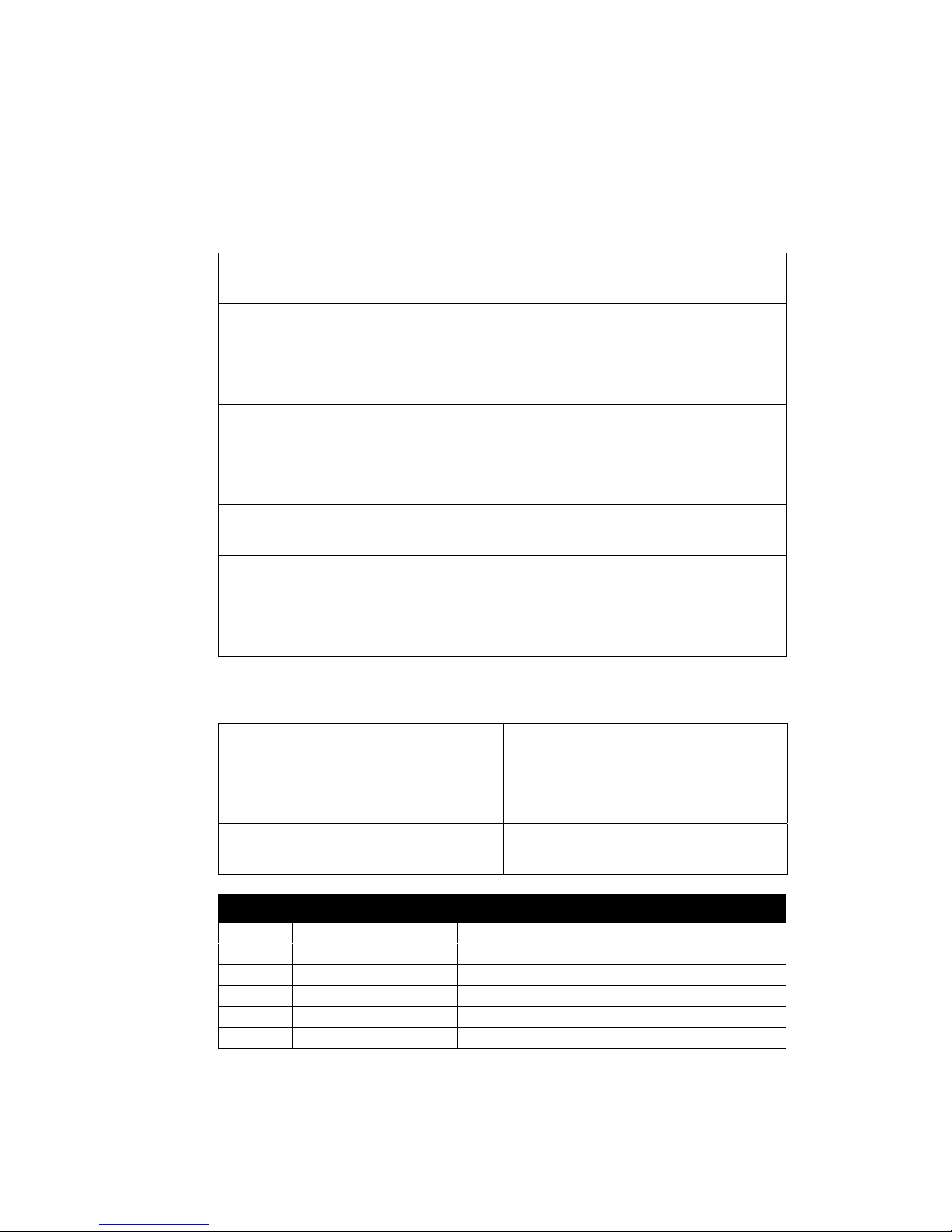
7. Technical Data
Digital Display
4 digit, LCD 15 mm height with automatic
decimal point units and error warning lamps
Working temperature 0...+40°C rel. humidity max. 65%
Calibration temperature 20°C
Storage temperature -20°C ... +50°C
Mains connection 100/120/220/240V + 10 - 13% 47-63 Hz
Warm-up time Approx. 30 mins.
Size (mm.)
215 x 88 x 250 (WHD), ½ 19" rack
2U high
Mass 3.5 Kgs.
Measurement
Resistance True four terminal measurement
with fixed dc measuring currents.
Measuring time Approx. 0.5 seconds
Auto-zero
Permits the automatic zero of
amplifiers eliminating errors due to
thermal emf
Range Resolution
Typical
Current
Accuracy @ 20°C ±5°C,
1 year
Temperature Coefficient/°C
4k
Ω 1 Ω
100 µA ±(0.05% Rdg +0.02% FS)
30 ppm Rdg + 1 ppm FS
400
Ω
100 m
Ω
1 mA
±
(0.05% Rdg +0.02% FS)
30 ppm Rdg + 1 ppm FS
40
Ω
10 m
Ω
10 mA
±
(0.05% Rdg +0.02% FS)
30 ppm Rdg + 1 ppm FS
4
Ω 1mΩ
10 mA
±
(0.05% Rdg +0.03% FS)
30 ppm Rdg + 4 ppm FS
400m
Ω
100
µΩ
10 mA
±
(0.05% Rdg +0.05% FS)
30 ppm Rdg +25 ppm FS
40m
Ω
10
µΩ
100 mA
±
(0.05% Rdg +0.05% FS)
30 ppm Rdg +25 ppm FS
Page 8
DO4A Issue 3/2001
8
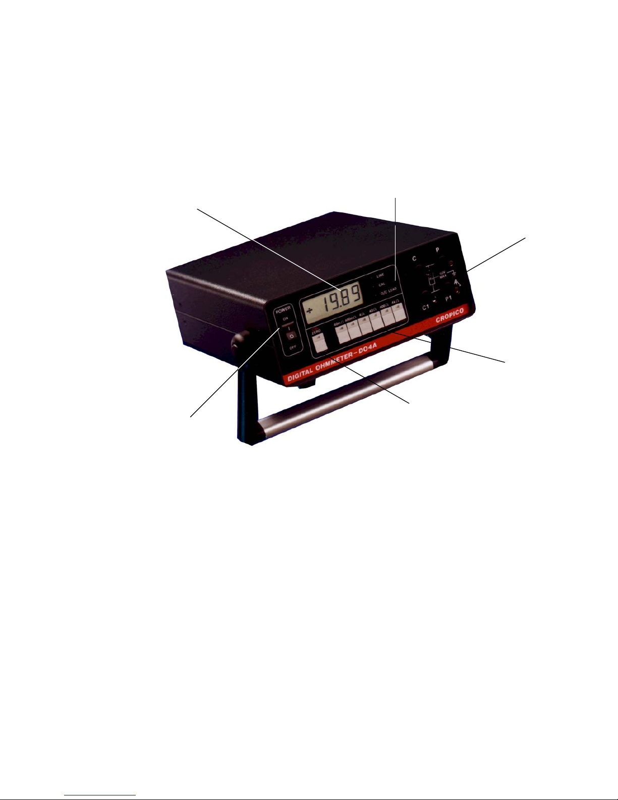
8. Description of Controls
Fig. 8-1 Description of Controls
8.1 Auto-zero
For measurements where thermal emf can cause a large measuring zero error, it is
possible to cancel this using the auto-zero button. First connect the potential leads to
the sample to be measured in the usual way, then connect the C & C1 terminals
together at the sample.
Press the auto-zero, the LED will illuminate and the zero offset will be measured and
stored as an offset. Reconnect the current leads in the normal measurement
configuration and the resistance reading will be displayed with the zero offset
eliminated. The LED will stay lit to warn that an offset is stored. This offset and
lamp will be cancelled if the range is changed or the instrument switched off. A
maximum of ±100 digits can be offset.
4 DIGIT LCD
DISPLAY
ON/OFF
POWER
SWITCH
STATUS
WARNING
LAMPS
MEASURING
TERMINALS
6 RANGE
SWITCHES
AUTO ZERO &
CALIBRATION
Page 9

DO4A Issue 3/2001
9
Range Selection:
The 6 ranges may be selected manually by simply pressing the desired range button.
The selected range will be indicated by an LED; over-range will be indicated by the
display reading - - - -.
Error & Status Lamps
These LEDs will light to indicate the instrument status.
LINE : Mains supply is connected to the instrument.
CAL : Calibration mode has been initialised by the rear key switch
and the instrument is in calibration mode.
O/C LEAD : One of the measuring leads is open circuit, to high
resistance, or not connected to test sample correctly. The
internal protection fuse is open circuit.
9. Methods of Measurement
9.1 Ohmmeter Connections
The Digital Ohmmeter type DO4A employs a four-wire method of measurement, ie.
it is necessary to make four connections to the resistor under test. The instrument is
supplied with four leads; two for the potential connections which are made across the
test resistor at the points between which the resistance is to be determined, and two
for the current connections which connects the test resistor to the supply circuit.
a) Connect the black leads to the C1 and P1 terminals, and the red leads to
terminals C and P. It is immaterial which leads of the pair goes to the P or C
terminals.
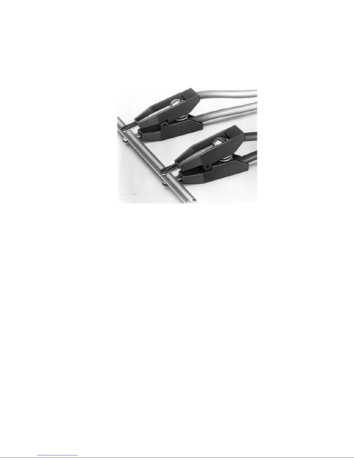
b) Clip on to the resistor under test fig. 9.1. Cleanliness is important and if the
sample is not clean, a rub with an abrasive paper to remove oxides is
recommended.
c) It is not always possible to use the combined current and potential clips, in
which case test leads with spade tags or special test fixtures may have to be
made for the user to suit particular applications.
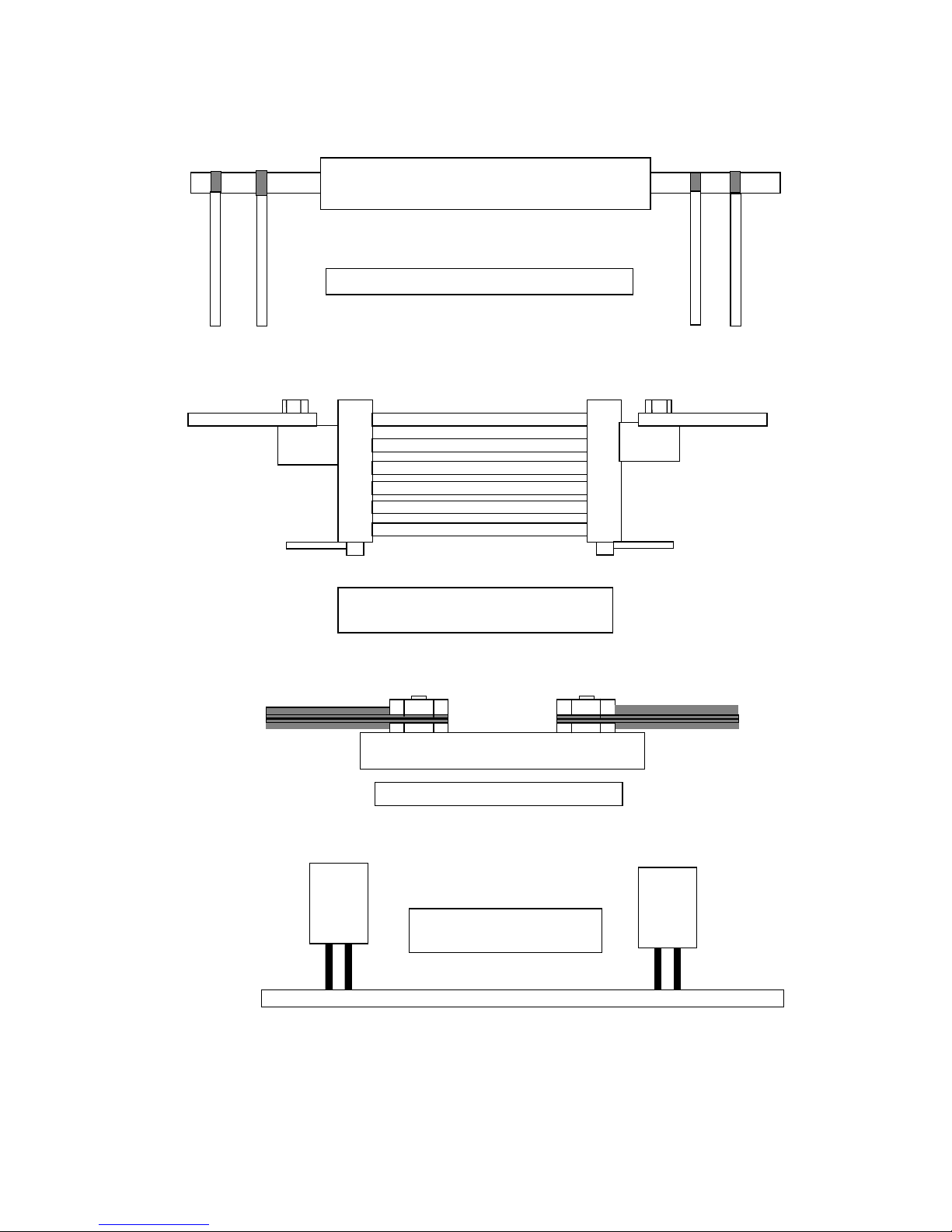
d) Fig. 8.3 illustrates connections to various types of test resistors.
e) When measuring 4 terminal resistance standards, do not use the combined
current and potential probes, make four separate connections to the current
and potential terminals.
Page 10
DO4A Issue 3/2001
10
Fig. 8.2 Combined current and potential probes
Page 11
DO4A Issue 3/2001
11
Fig. 8.3 Various types of resistors
C1 P1
CP
C1
C
P1
P
Connections to Current Shunt
Connection to Cable Joint
C
1
P1
P C
Measurement with duplex
handspikes
C1
C
P1 P
Connections to Stud Terminals
Page 12

DO4A Issue 3/2001
12
10. Power Up
When the DO4A is first switched on, a lamp test is automatically performed, all
display segments are illuminated followed by each LED lighting in sequence. The
microprocessor checks for correct internal operation and indicates "P" if all tests pass
O.K. At the same time the software version will be displayed and held for
approximately 2 seconds. The display will typically read "P 1.1". Should the
internal checks indicate an error, then the display will read "HELP". To rectify this,
see section 13.
The DO4A will perform an automatic zero sequence and finally sets to the following
default start up mode ready for use. The measuring range 4KΩ selected, auto-zero
lamp out.
11. Measurement
Connect the resistance to be measured (Rx) to the measuring terminals in accordance
with the diagram on the instrument panel. Select the range required. The green LED
lamp will light to indicate which buttons are active.
CAUTION: Do not auto-zero when Rx is connected for measurement. This will
store a large offset made up of resistance and thermal emf and displayed values will
be invalid.
If, during measurement, any of the error messages should be displayed, then
obviously the appropriate action should be taken. Whilst the input is protected
against accidental application of mains voltage, single or 3-phase, care should be
taken to avoid measuring on live circuits.
Over-range
The display will indicate - - - -.
Open Circuit Lead
O/C Lead will be displayed if the instrument detects that the lead resistance is too
high. The C terminals are checked for compliance voltage. Measurement should not
be made if this warning message is displayed. This warning will also be displayed if
the internal protection fuse is open circuit.
Page 13

DO4A Issue 3/2001
13
Connections
When making good quality measurements, it is important to ensure that all measuring
leads are in good condition, and less than 0.2 ohms resistance.
It should also be noted that some spade tags and crocodile clips can produce high
thermal emfs when warmed, particularly nickel-plated brass types. This can cause
problems when, for example, connecting too hot motor windings. The solution is to
use plain copper or brass connections keeping them clean and oxide free.
12. Protection
Every effort has been made to protect the instrument against voltages being applied
to the terminals. A large 6 Amp fuse is fitted internally to the C measuring line and a
gas discharge tube, GDT, is across the C terminals. If voltages above approximately
90V are applied to the measuring terminals, the GDT will strike effectively shorting
the C terminals through the 6 Amp protective fuse, which will interrupt the circuit.
The fuse fitted will interrupt up to 40,000 Amps. The P terminals are not fused and
will withstand up to 460 Volts without damage to the instrument.
WARNING!
To replace the protection fuse, the top instrument panel should be removed, but only
after the mains supply and all input connections are removed. The protection
fuse is located on the main printed circuit board. Only replace with the correct fuse
rating.
13. Calibration Process
WARNING! This should only be carried out by competent and trained personnel.
The calibration is carried out from the front panel and no mechanical adjustments are
necessary.
Equipment required - Milliohmmeter Test Standard type MTS2 or a set of Resistance
standards 4mΩ, 40mΩ, 400mΩ, 4Ω, and 400Ω and 4kΩ. A calibration key is
supplied with the instrument.
The DO4A is designed to eliminate all calibration. The factory adjusted internal
standards are constructed to give long term stability and minimal drift. However, for
those wishing to adjust the ohmmeter, proceed as follows.
Page 14
DO4A Issue 3/2001
14
The ohmmeter should be placed in a temperature controlled environment for at least
2 hours before calibration.
Select the 4mΩ range and connect a 4 milliohm Standard. This Standard should be
within 0.01% or better of the nominal value. Press the CAL button and the DO4A
will automatically measure the standard and store any calibration offsets.
With the Standard still connected, remove the C lead from the resistance and connect
it to the C1 terminal. This effectively gives a zero value; press CAL again and the
zero error is stored. Select the next range and appropriate full scale Standard and
repeat the above procedure. All ranges should be calibrated in this way, ie. for both
full scale and zero, the key being turned back to the run position and removed on
completion.
NOTE: Should the calibration constants be corrupted, then the display will indicate
HELP. To re-initialise the calibration memory, turn the calibration key to the CAL
position, remove the top cover and press the red reset button on the main PCB. The
instrument should be switched on, but the mains power supply MUST BE
DISCONNECTED before removing the top cover.
After resetting the instrument, the full calibration procedure must be fully
implemented to return the instrument to its full accuracy.
Repeated corruption of the memory and display of the HELP error message indicates
a malfunction of the instrument, which should be returned to our Service facility for
rectification.
A comprehensive repair and calibration service is available at our factory. When
returning instruments, please ensure adequate packing to avoid damage in transit.
14. ACCESSORIES
14.1
LEADS The DO4A may be used with a variety of lead sets. The
following are the available selection. Remember, if you do not see
suitable leads for your application ,please consult our customer help desk.
Ordering Code Description
HS01-P Duplex Handspikes with 2.5 metre lead length, current and
potential spikes suitable for plate or Bussbar
measurements.
HS02-P Duplex Handspikes as a HS01-P but with 2.5 and 15 metre
lead lengths
LS03-P Large Kelvin clips with 3 metre lead length suitable for
attaching to rods bars or cables up to 38mm diameter
LS04-P As LS03-P but with lead lengths 3 and 15 metres
LS05 Executive lead set consisting of 4 x 1 metre leads with
Page 15
DO4A Issue 3/2001
15
banana plugs, 4 x crocodile clips 4 x test prods and 4 x
Kelvin clips (KC1) jaw opening 4mm
LS06-P Kelvin lead set comprising of miniature Kelvin clips (KC2)
with 1 meter leads attached terminated with banana plugs
Jaw opening 6mm. Suitable for fine wires.
14.2
WIRE CLAMPS For the precise measurement of 1 meter cable samples
we offer 2 wire clamp options.
Ordering Code Description
C01 1 metre wire clamp with hardwood base suitable for cable
diameters up to 25mm
C02 1 metre wire clamp with metal base and provision for
temperature sensor suitable for wire cross section 1 to
1000mm
 Loading...