

Page 1
Revision 1.0 as of 2012-05-10
cronologic GmbH & Co. KG
User Guide
1
Page 2

Page 3
This document is published by cronologic GmbH & Co. KG.
Copyright©2012 cronologic GmbH & Co. KG. All rights reserved.
Information in this document is subject to change without notice and does not
represent a commitment on the part of cronologic GmbH & Co. KG.
For requests or feedback you can contact cronologic GmbH & Co. KG:
Address: cronologic GmbH & Co. KG
Jahnstrasse 49
D-60318 Frankfurt
Phone: +49 (0)69 173 20 256-0
Fax: +49 (0)69 173 20 256-9
Email: [email protected]
WWW:
http://www.cronologic.de
Page 4

Page 5
Contents
1 Overview 1
1.1 Parts List . . . . . . . . . . . . . . . . . . . . . . . . . . . . . . . . . . . . . . . . 1
1.2 Environmental Conditions . . . . . . . . . . . . . . . . . . . . . . . . . . . . . . . 1
2 Component Identication 3
2.1 Front Panel . . . . . . . . . . . . . . . . . . . . . . . . . . . . . . . . . . . . . . . 3
2.2 PCIe Host Card . . . . . . . . . . . . . . . . . . . . . . . . . . . . . . . . . . . . . 3
2.3 Internal View . . . . . . . . . . . . . . . . . . . . . . . . . . . . . . . . . . . . . . 4
2.4 Electrical Specications . . . . . . . . . . . . . . . . . . . . . . . . . . . . . . . . 5
2.4.1 Power Supply . . . . . . . . . . . . . . . . . . . . . . . . . . . . . . . . . . 5
2.4.2 Electrical Load of each Power Supply Rail . . . . . . . . . . . . . . . . . . 6
2.4.3 Electrical Load per Slot . . . . . . . . . . . . . . . . . . . . . . . . . . . . 7
3 Installation 9
3.1 Installation of the PCIe x16 host card . . . . . . . . . . . . . . . . . . . . . . . . 9
3.2 Installation of 3rd party PCIe cards . . . . . . . . . . . . . . . . . . . . . . . . . 9
3.3 Connecting the Ndigo Crate to the PCIe x16 host card . . . . . . . . . . . . . . . 11
3.4 Function Control . . . . . . . . . . . . . . . . . . . . . . . . . . . . . . . . . . . . 11
3.5 Maintenance . . . . . . . . . . . . . . . . . . . . . . . . . . . . . . . . . . . . . . . 12
4 Regularity Compliance and Recycling 13
iii
Page 6
1 Overview
The Ndigo Crate is a PCI Express (PCIe) expansion enclosure containing 8 x16 PCIe2 slots.
The Ndigo Crate connects to a host computer using an adapter (PCIe expansion card) which is
plugged into a PCIe2 or PCIe x16 slot via a x16 cable. Depending on the variant of the Ndigo
Crate up to 8 PCIe2 slots and two PCI slots are functionally connected to the base board (see
Table??).
The Ndigo Crate was specically designed to operate multiple synchronized digitizer boards
by cronologic GmbH & Co. KG thereby providing a high speed data acquisition (DAQ) system.
It can also be used to house other PCIe and PCI devices such as DAQ cards, GPUs for high
performance computing, storage adapters or networking equipment. The PCIe expansion card
is already installed into the expansion enclosure.
1.1 Parts List
The following parts are provided with the Ndigo Crate: see table 1.2.
Quantity Part
1 Ndigo Crate with power supply and extension board installed.
1 PCIe x16 host card
1 PCIe x16 host cable (3 meter)
1 Power cord (220Vac)
Table 1.1: Parts shipped with the Ndigo Crate.
1.2 Environmental Conditions
Operating temperature range
5◦C to 40◦C
Storage temperature range
−10◦C to 60◦C
Relative humidity (non-condensing)
<
90%
Table 1.2: Parts shipped with the Ndigo Crate.
1
Page 7

Page 8
2 Component Identication
2.1 Front Panel
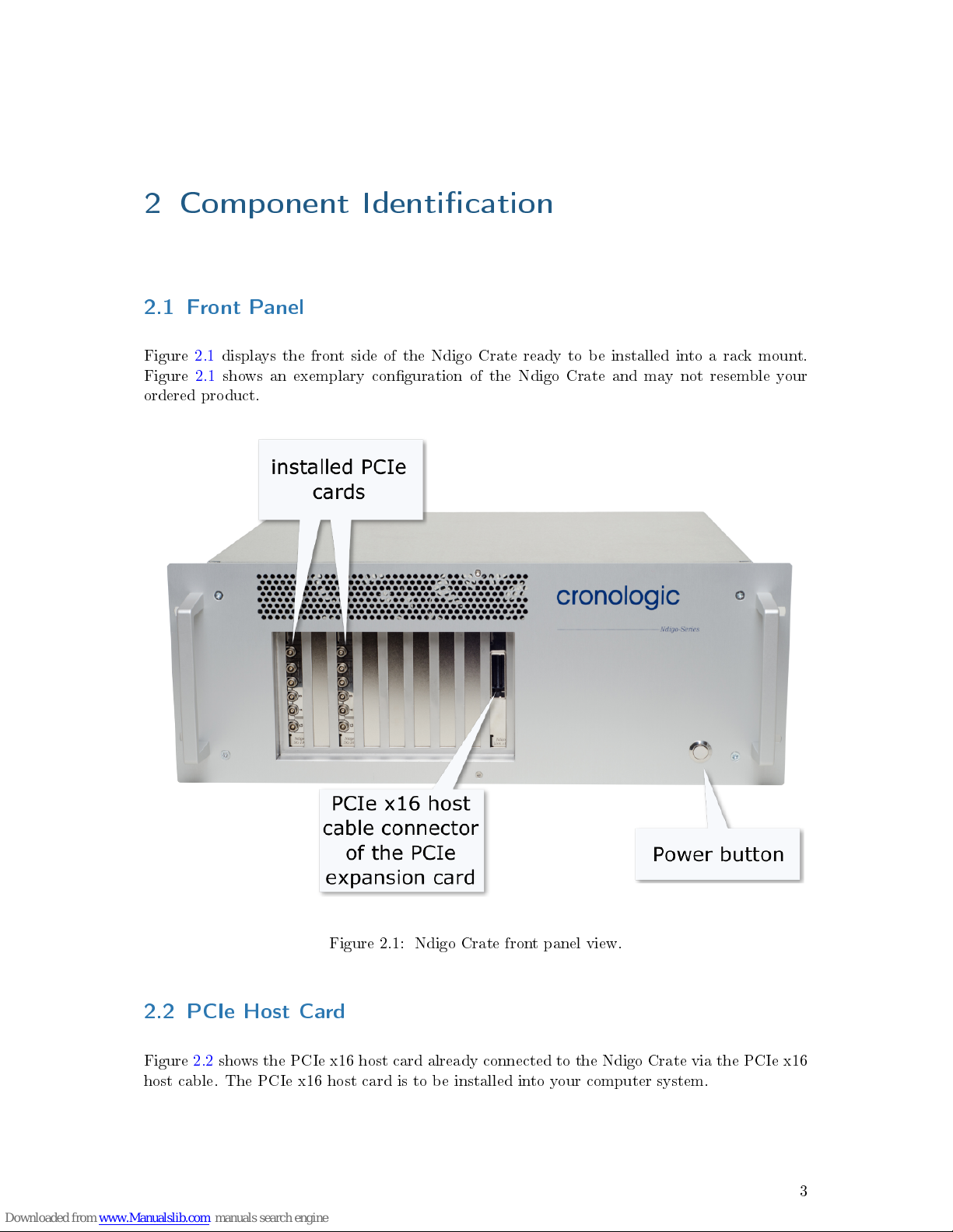
Figure 2.1 displays the front side of the Ndigo Crate ready to be installed into a rack mount.
Figure 2.1 shows an exemplary conguration of the Ndigo Crate and may not resemble your
ordered product.
Figure 2.1: Ndigo Crate front panel view.
2.2 PCIe Host Card
Figure 2.2 shows the PCIe x16 host card already connected to the Ndigo Crate via the PCIe x16
host cable. The PCIe x16 host card is to be installed into your computer system.
3
Page 9
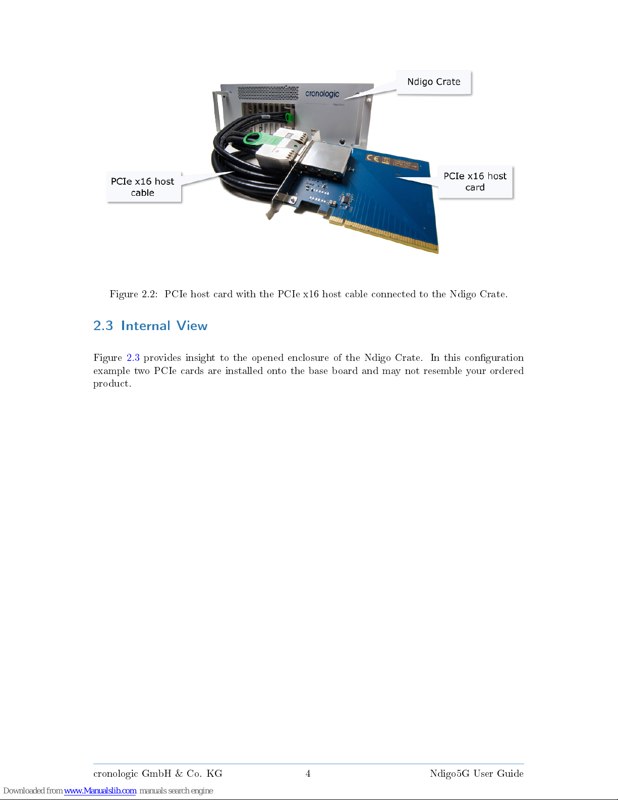
Figure 2.2: PCIe host card with the PCIe x16 host cable connected to the Ndigo Crate.
2.3 Internal View
Figure 2.3 provides insight to the opened enclosure of the Ndigo Crate. In this conguration
example two PCIe cards are installed onto the base board and may not resemble your ordered
product.
cronologic GmbH & Co. KG 4 Ndigo5G User Guide
Page 10
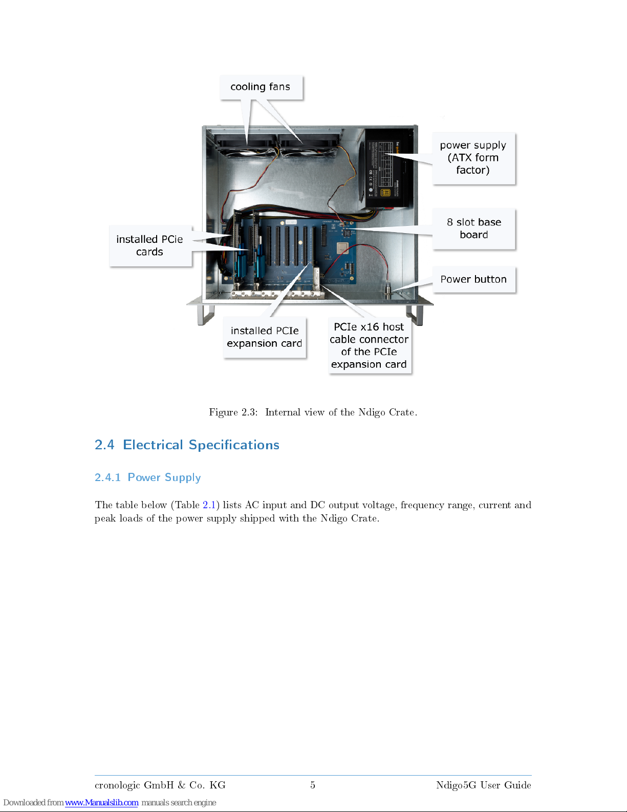
Figure 2.3: Internal view of the Ndigo Crate.
2.4 Electrical Specications
2.4.1 Power Supply
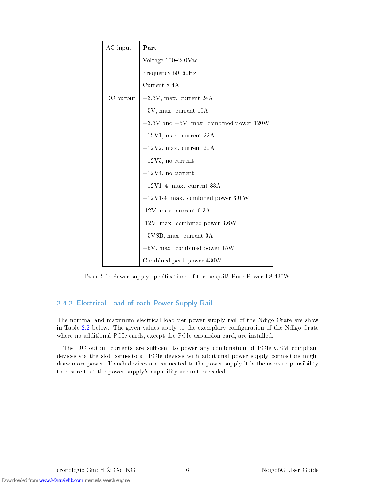
The table below (Table 2.1) lists AC input and DC output voltage, frequency range, current and
peak loads of the power supply shipped with the Ndigo Crate.
cronologic GmbH & Co. KG 5 Ndigo5G User Guide
Page 11
AC input
Part
Voltage 100240Vac
Frequency 5060Hz
Current 8-4A
DC output +3.3V, max. current 24A
+5V, max. current 15A
+3.3V and +5V, max. combined power 120W
+12V1, max. current 22A
+12V2, max. current 20A
+12V3, no current
+12V4, no current
+12V14, max. current 33A
+12V1-4, max. combined power 396W
-12V, max. current 0.3A
-12V, max. combined power 3.6W
+5VSB, max. current 3A
+5V, max. combined power 15W
Combined peak power 430W
Table 2.1: Power supply specications of the be quit! Pure Power L8-430W.
2.4.2 Electrical Load of each Power Supply Rail
The nominal and maximum electrical load per power supply rail of the Ndigo Crate are show
in Table 2.2 below. The given values apply to the exemplary conguration of the Ndigo Crate
where no additional PCIe cards, except the PCIe expansion card, are installed.
The DC output currents are sucent to power any combination of PCIe CEM compliant
devices via the slot connectors. PCIe devices with additional power supply connectors might
draw more power. If such devices are connected to the power supply it is the users responsibility
to ensure that the power supply's capability are not exceeded.
cronologic GmbH & Co. KG 6 Ndigo5G User Guide
Page 12
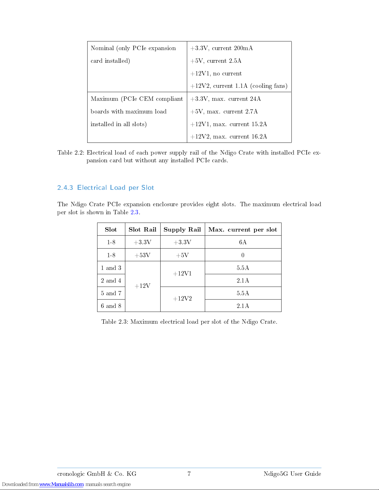
Nominal (only PCIe expansion +3.3V, current 200mA
card installed) +5V, current 2.5A
+12V1, no current
+12V2, current 1.1A (cooling fans)
Maximum (PCIe CEM compliant +3.3V, max. current 24A
boards with maximum load +5V, max. current 2.7A
installed in all slots) +12V1, max. current 15.2A
+12V2, max. current 16.2A
Table 2.2: Electrical load of each power supply rail of the Ndigo Crate with installed PCIe ex-
pansion card but without any installed PCIe cards.
2.4.3 Electrical Load per Slot
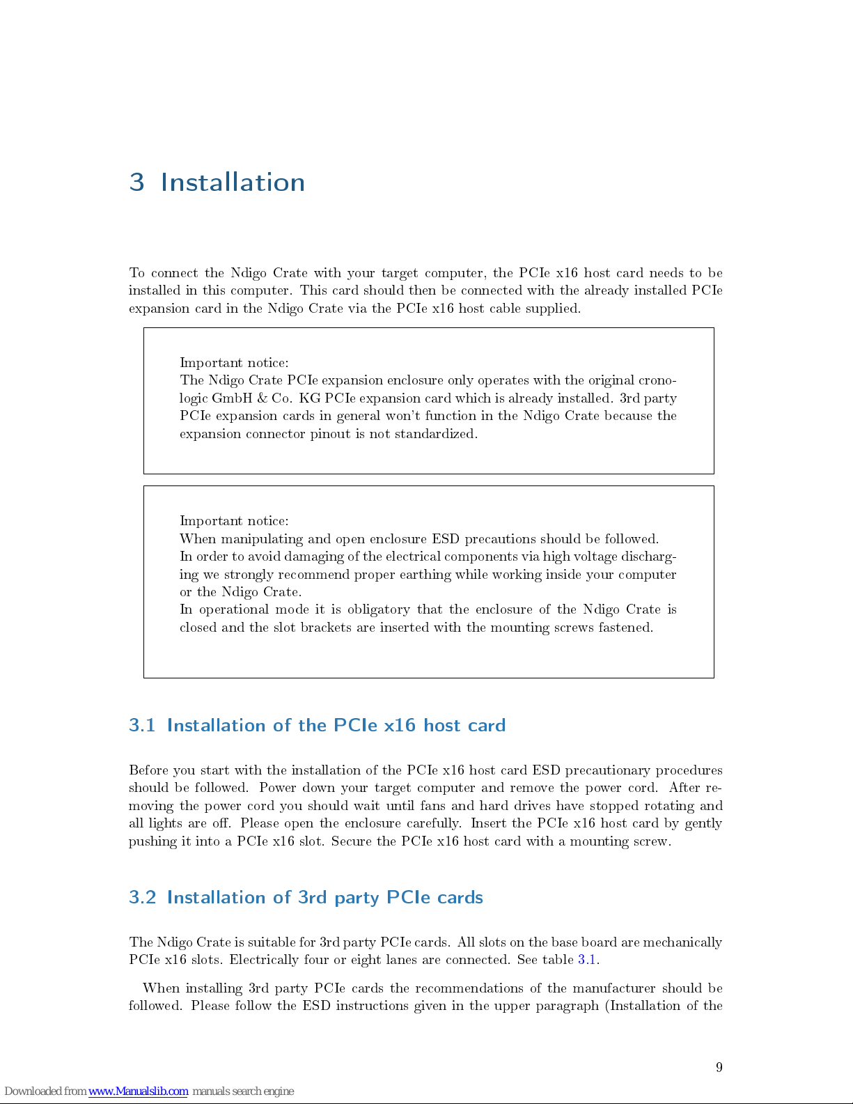
The Ndigo Crate PCIe expansion enclosure provides eight slots. The maximum electrical load
per slot is shown in Table 2.3.
Slot Slot Rail Supply Rail Max. current per slot
1-8 +3.3V +3.3V 6A
1-8 +53V +5V 0
1 and 3
+12V
+12V1
5.5A
2 and 4 2.1A
5 and 7
+12V2
5.5A
6 and 8 2.1A
Table 2.3: Maximum electrical load per slot of the Ndigo Crate.
cronologic GmbH & Co. KG 7 Ndigo5G User Guide
Page 13

Page 14
3 Installation
To connect the Ndigo Crate with your target computer, the PCIe x16 host card needs to be
installed in this computer. This card should then be connected with the already installed PCIe
expansion card in the Ndigo Crate via the PCIe x16 host cable supplied.
Important notice:
The Ndigo Crate PCIe expansion enclosure only operates with the original crono-
logic GmbH & Co. KG PCIe expansion card which is already installed. 3rd party
PCIe expansion cards in general won't function in the Ndigo Crate because the
expansion connector pinout is not standardized.
Important notice:
When manipulating and open enclosure ESD precautions should be followed.
In order to avoid damaging of the electrical components via high voltage discharg-
ing we strongly recommend proper earthing while working inside your computer
or the Ndigo Crate.
In operational mode it is obligatory that the enclosure of the Ndigo Crate is
closed and the slot brackets are inserted with the mounting screws fastened.
3.1 Installation of the PCIe x16 host card
Before you start with the installation of the PCIe x16 host card ESD precautionary procedures
should be followed. Power down your target computer and remove the power cord. After re-
moving the power cord you should wait until fans and hard drives have stopped rotating and
all lights are o. Please open the enclosure carefully. Insert the PCIe x16 host card by gently
pushing it into a PCIe x16 slot. Secure the PCIe x16 host card with a mounting screw.
3.2 Installation of 3rd party PCIe cards
The Ndigo Crate is suitable for 3rd party PCIe cards. All slots on the base board are mechanically
PCIe x16 slots. Electrically four or eight lanes are connected. See table 3.1.
When installing 3rd party PCIe cards the recommendations of the manufacturer should be
followed. Please follow the ESD instructions given in the upper paragraph (Installation of the
9
Page 15
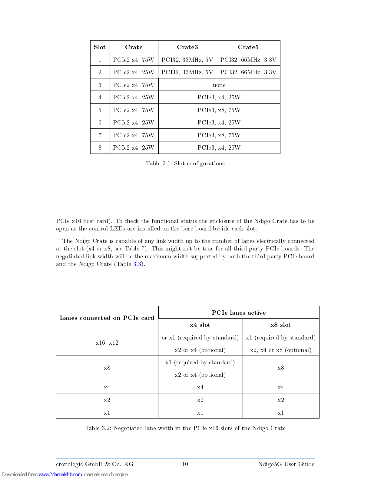
Slot Crate Crate3 Crate5
1 PCIe2 x4, 75W PCI32, 33MHz, 5V PCI32, 66MHz, 3.3V
2 PCIe2 x4, 25W PCI32, 33MHz, 5V PCI32, 66MHz, 3.3V
3 PCIe2 x4, 75W none
4 PCIe2 x4, 25W PCIe3, x4, 25W
5 PCIe2 x4, 75W PCIe3, x8, 75W
6 PCIe2 x4, 25W PCIe3, x4, 25W
7 PCIe2 x4, 75W PCIe3, x8, 75W
8 PCIe2 x4, 25W PCIe3, x4, 25W
Table 3.1: Slot congurations
PCIe x16 host card). To check the functional status the enclosure of the Ndigo Crate has to be
open as the control LEDs are installed on the base board beside each slot.
The Ndigo Crate is capable of any link width up to the number of lanes electrically connected
at the slot (x4 or x8, see Table 7). This might not be true for all third party PCIe boards. The
negotiated link width will be the maximum width supported by both the third party PCIe board
and the Ndigo Crate (Table 3.3).
Lanes connected on PCIe card
PCIe lanes active
x4 slot x8 slot
x16, x12
or x1 (required by standard) x1 (required by standard)
x2 or x4 (optional) x2, x4 or x8 (optional)
x8
x1 (required by standard)
x8
x2 or x4 (optional)
x4 x4 x4
x2 x2 x2
x1 x1 x1
Table 3.2: Negotiated lane width in the PCIe x16 slots of the Ndigo Crate
cronologic GmbH & Co. KG 10 Ndigo5G User Guide
Page 16
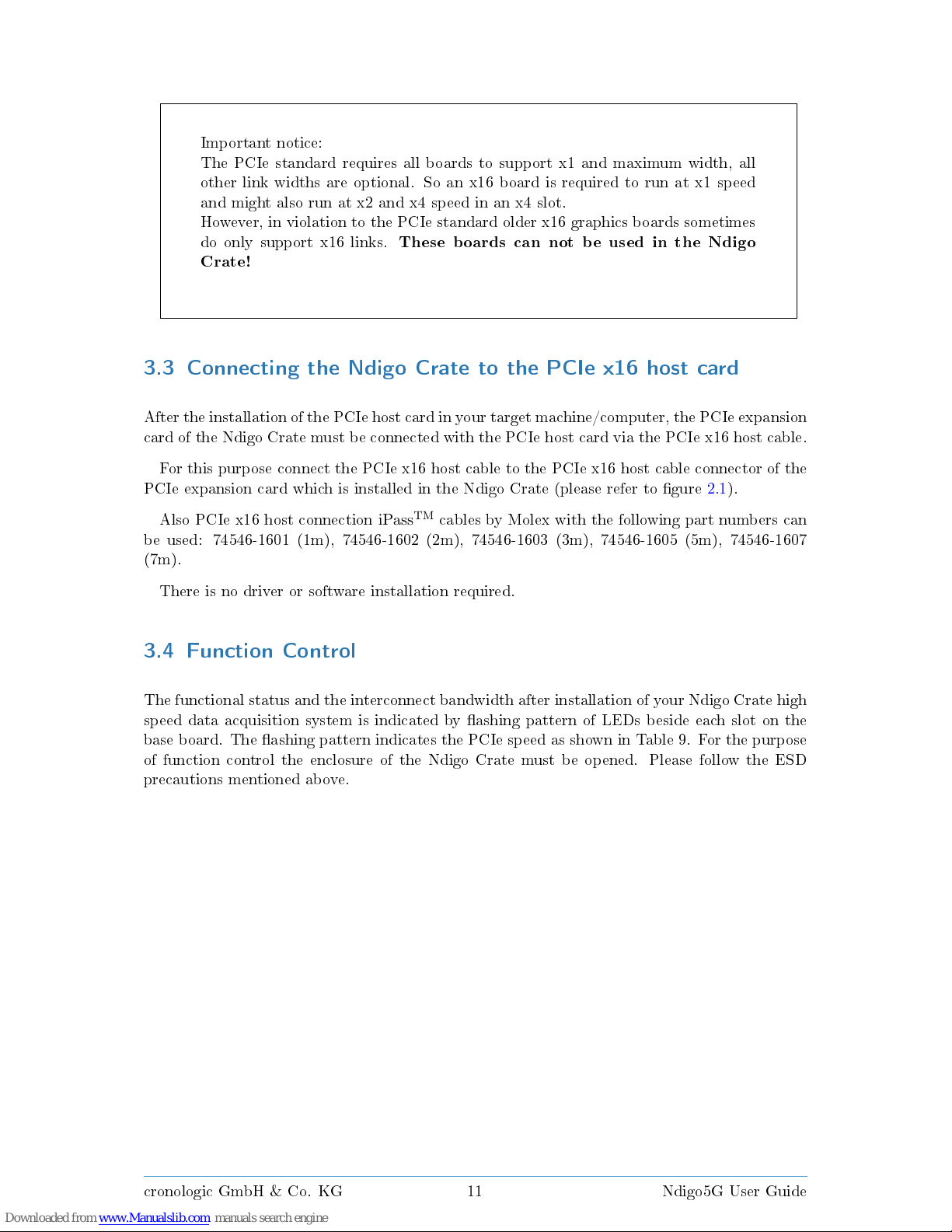
Important notice:
The PCIe standard requires all boards to support x1 and maximum width, all
other link widths are optional. So an x16 board is required to run at x1 speed
and might also run at x2 and x4 speed in an x4 slot.
However, in violation to the PCIe standard older x16 graphics boards sometimes
do only support x16 links.
These boards can not be used in the Ndigo
Crate!
3.3 Connecting the Ndigo Crate to the PCIe x16 host card
After the installation of the PCIe host card in your target machine/computer, the PCIe expansion
card of the Ndigo Crate must be connected with the PCIe host card via the PCIe x16 host cable.
For this purpose connect the PCIe x16 host cable to the PCIe x16 host cable connector of the
PCIe expansion card which is installed in the Ndigo Crate (please refer to gure 2.1).
Also PCIe x16 host connection
iPassTMcables by Molex with the following part numbers can
be used: 74546-1601 (1m), 74546-1602 (2m), 74546-1603 (3m), 74546-1605 (5m), 74546-1607
(7m).
There is no driver or software installation required.
3.4 Function Control
The functional status and the interconnect bandwidth after installation of your Ndigo Crate high
speed data acquisition system is indicated by ashing pattern of LEDs beside each slot on the
base board. The ashing pattern indicates the PCIe speed as shown in Table 9. For the purpose
of function control the enclosure of the Ndigo Crate must be opened. Please follow the ESD
precautions mentioned above.
cronologic GmbH & Co. KG 11 Ndigo5G User Guide
Page 17
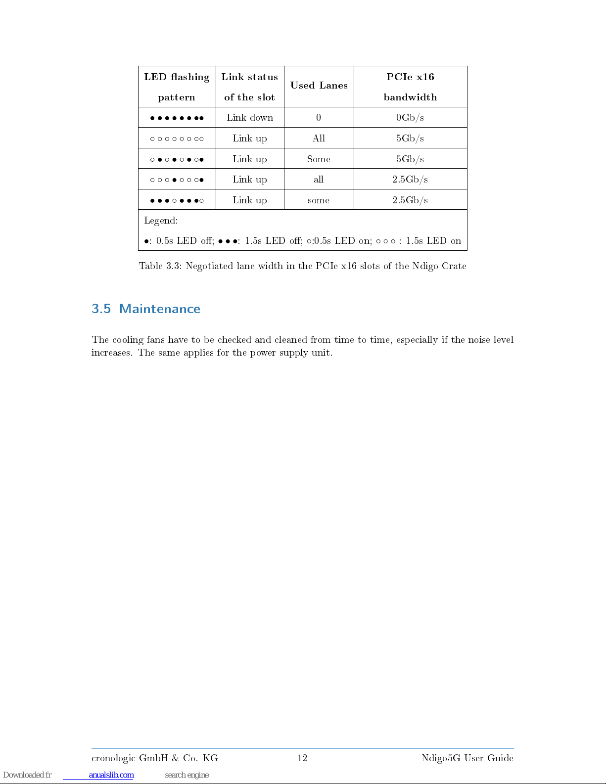
LED ashing Link status
Used Lanes
PCIe x16
pattern of the slot bandwidth
• • • • • • ••
Link down 0 0Gb/s
◦ ◦ ◦ ◦ ◦ ◦ ◦◦
Link up All 5Gb/s
◦ • ◦ • ◦ • ◦•
Link up Some 5Gb/s
◦ ◦ ◦ • ◦ ◦ ◦•
Link up all 2.5Gb/s
• • • ◦ • • •◦
Link up some 2.5Gb/s
Legend:
•
: 0.5s LED o;
• • •
: 1.5s LED o;◦:0.5s LED on;
◦ ◦ ◦
: 1.5s LED on
Table 3.3: Negotiated lane width in the PCIe x16 slots of the Ndigo Crate
3.5 Maintenance
The cooling fans have to be checked and cleaned from time to time, especially if the noise level
increases. The same applies for the power supply unit.
cronologic GmbH & Co. KG 12 Ndigo5G User Guide
Page 18
4 Regularity Compliance and Recycling
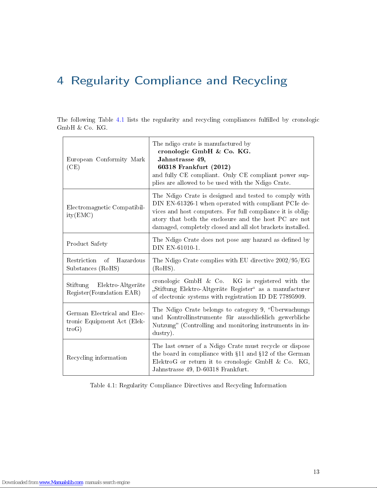
The following Table 4.1 lists the regularity and recycling compliances fullled by cronologic
GmbH & Co. KG.
European Conformity Mark
(CE)
The ndigo crate is manufactured by
cronologic GmbH & Co. KG.
Jahnstrasse 49,
60318 Frankfurt (2012)
and fully CE compliant. Only CE compliant power sup-
plies are allowed to be used with the Ndigo Crate.
Electromagnetic Compatibil-
ity(EMC)
The Ndigo Crate is designed and tested to comply with
DIN EN-61326-1 when operated with compliant PCIe de-
vices and host computers. For full compliance it is oblig-
atory that both the enclosure and the host PC are not
damaged, completely closed and all slot brackets installed.
Product Safety
The Ndigo Crate does not pose any hazard as dened by
DIN EN-61010-1.
Restriction of Hazardous
Substances (RoHS)
The Ndigo Crate complies with EU directive 2002/95/EG
(RoHS).
Stiftung Elektro-Altgeräte
Register(Foundation EAR)
cronologic GmbH & Co. KG is registered with the
Stiftung Elektro-Altgeräte Register as a manufacturer
of electronic systems with registration ID DE 77895909.
German Electrical and Elec-
tronic Equipment Act (Elek-
troG)
The Ndigo Crate belongs to category 9, Überwachungs
und Kontrollinstrumente für ausschlieÿlich gewerbliche
Nutzung (Controlling and monitoring instruments in in-
dustry).
Recycling information
The last owner of a Ndigo Crate must recycle or dispose
the board in compliance with 11 and 12 of the German
ElektroG or return it to cronologic GmbH & Co. KG,
Jahnstrasse 49, D-60318 Frankfurt.
Table 4.1: Regularity Compliance Directives and Recycling Information
13
 Loading...