

Page 1
USER MANUAL
High-precisionDigital Imager
Hangzhou CRON Machinery & Electronics Co., Ltd.
Jinyi Road 875, Xiaoshan Economic & Technological
Development Zone Hangzhou, 311215, P.R.China
TEL:0571-82838989 FAX:0571-82838877
1 / 55
Page 2

Revision History Version: A1 Date: 2017-11-12
Version: A2 Date: 2018-4-19
2 / 55
Page 3

Contents
Chapter 1:About this manual ............................................................................................. 4
Chapter 2:Overview ........................................................................................................... 4
2.1 Overview ...........................................................................................................................5
2.2 System dimension& weight...............................................................................................6
2.3 Power requirement ...........................................................................................................6
2.4 Power connection & wiring ...............................................................................................6
2.5 Safety & Cautions labels ....................................................................................................7
2.6 Safety Information ............................................................................................................9
Chapter 3:Installation Site and Environmental Requirements ........................................... 10
3.1 Space requirement ..........................................................................................................10
3.2 Flooring & hallway access ...............................................................................................10
3.3 Environmental requirement ............................................................................................10
Chapter 4:Offloading, Unboxing and Installing ................................................................. 11
4.1 On-site conditions during handling .................................................................................11
4.2 Shipment packing ............................................................................................................11
4.3 Loading & unloading equipment .....................................................................................11
4.4 Installation personnel......................................................................................................11
4.5 Offloading, unboxing and installation .............................................................................12
Chapter 5:Operation Instructions ..................................................................................... 17
5.1 Turning onthe device ......................................................................................................17
5.2 Connecting to computer .................................................................................................17
5.3 Laboo-HDI installation & startup.....................................................................................17
5.4Create work template ......................................................................................................22
Chapter 6:SystemMaintenance ........................................................................................ 35
6.1Equipment internal cleaniness check...............................................................................35
6.2 Daily routine maintenance ..............................................................................................40
Chapter 7:Abnormal Problems Analysis and Handling
7.1 Error message and handling suggestions
7.2
Common plate-making problems and causes ..................................................................44
7.3Common instruments used for plate testing process ......................................................45
Chapter 8: Consumables Parts and Spare Parts
8.1 HDI-600bundled parts list ............................................................................................45
8.2 HDI-920bundled parts list ............................................................................................48
8.3 HDI-1600bundled parts list ..........................................................................................49
Chapter 9:Appendixes–Wiring Diagrams
........................................................................41
................................................................. 45
........................................................................... 50
....................................................... 41
3 / 55
Page 4

About this manual
Chapter 1: About this manual
This document describes how to install and use the high-precision digital flexo imager HDI-600/920/1600
series
————————————————————————————————
Contents
The High-precision Digital Imager user's manual contains the following chapters:
Chapter 2: Overview
Chapter 3:Installation site and environmental requirements
Chapter 4:Offloading, unboxing and installing
Chapter 5:Operation instruction
Chapter 6:System maintenance
Chapter 7:Abnormal problems analysis and handling
Chapter 8:Vulnerable consumables and spare parts
Chapter 9:Appendixes
Typographic conventions
This document uses the following typographical conventions:
Calibri(Bold) Noun first defined and emphasis is indicated in bold
Calibri Represents the computer display of text and system items
————————————————————————————————
CRON welcomes any valuable comments and suggestions:
CRON welcomes your comments and suggestions on this document, and it’s our sincere commitment to provide upmost
relevant detail in this document to meet your requirements.
To send in any comments or suggestions, please visit http://www.cron.com.cn.
When submitting comments and suggestions, attach the titleof the document, indicates page number and any comments, errors
or suggestions for improvement found in this document.
If you want to know the upgrade items during production,please refer to the announcements by our company
Page 5
Overview
Chapter 2: Overview
2.1 Overview
a)High-precision Digital flexo Imager is a laser imaging technology,that directly applies high-precision
bitmap information imaging on digital flexo plates by using thermal laser ablation
technique.Generally it consists of flexo plate mounting drum, optical imaging system, laser driver
system, scanning device, plate mounting and releasing mechanism, vacuum adsorption, dedusting
device, the overall control system and other components.
b) Available flexographic precision resolution: 4000DPI、4800DPI、5080DPI、9600DPI.
Productivity >1.2m2/h, Dot reproduction: 1%-99%。
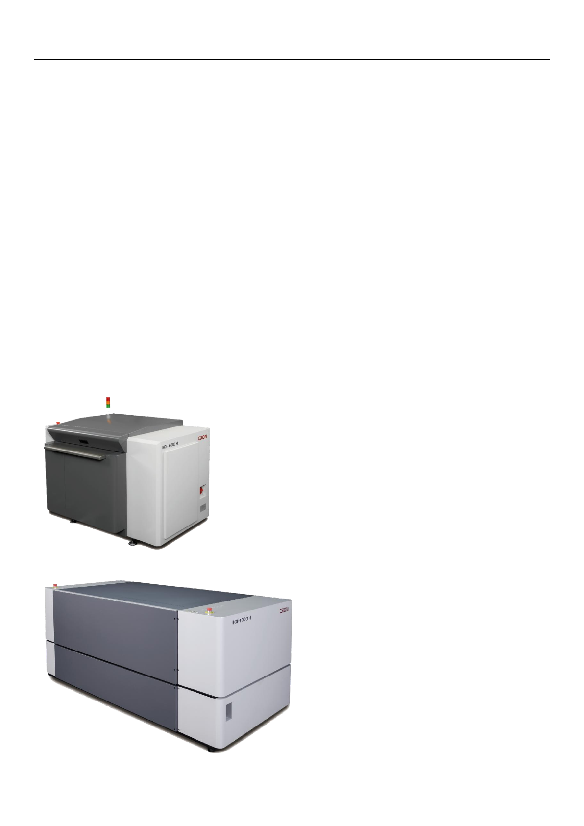
c) Format: HDI-600(660mm X 560mm), HDI-920(920mm X 675mm), HDI-1600(1524mm X 1200mm).
d)Materialsused are selection of environmentally friendly materials and comply with environmental
laws and regulations. We avoid using hazardous materials in the device and strong abide to
environmental protectionrequirements.
Figure illustration as shown Pictures 2-1, 2-2:
Picture 2-1: HDI-600、HDI-920
Picture 2-2: HDI-1600
5 / 55
Page 6
Overview
Device Model
W(cm)
L(cm)
H(cm)
Weight(kg)
HDI-600**
140
118
105
780
HDI-920**
170
130
110
880
HDI-1600**
232
115
118
1480
Device Model
Rated power (kW)
Power supply requirements
HDI-600**
5.1
200~240V 23A
HDI-920**
5.6
200~240V 25A
HDI-1600**
6.0
200~240V 27A
2.2 System dimension & weight
Table 2-1:System equipment size, weight table
Remark:System equipment, size, weight will be vary depends on required configurations
2.3Power requirement
Table 2-2:Power requirements of the system
2.4Power connection & wiring
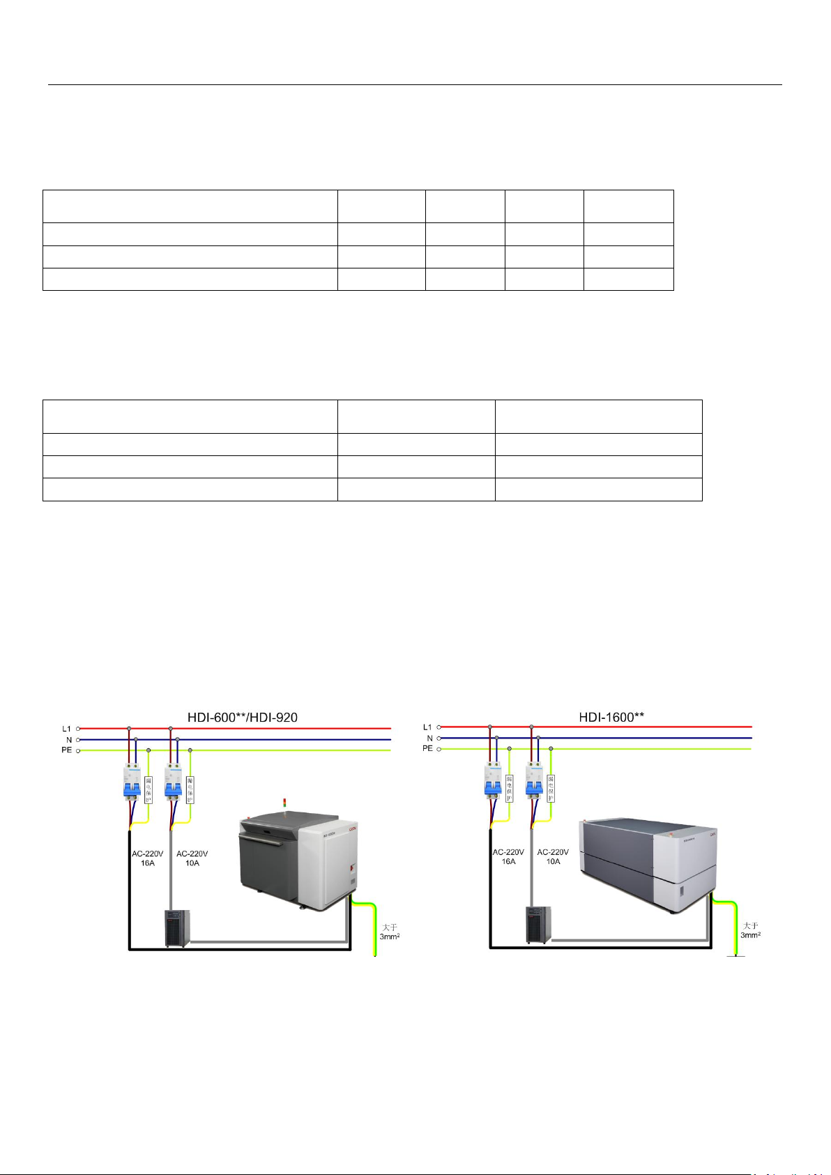
Preparation of the wires, sockets, open empty, etc. (if necessary, an UPS is required too)
Instruction:Required voltage must be stable. Grounding must be good (with galvanized metal diameter of
not less than 10mm, buried 1.5m below).
Equipment must be having ground resistance ≤ 0.5Ω.
Picture 2-4:power wiring diagram
6 / 55
Page 7
Overview
2.5Safety and Caution labels
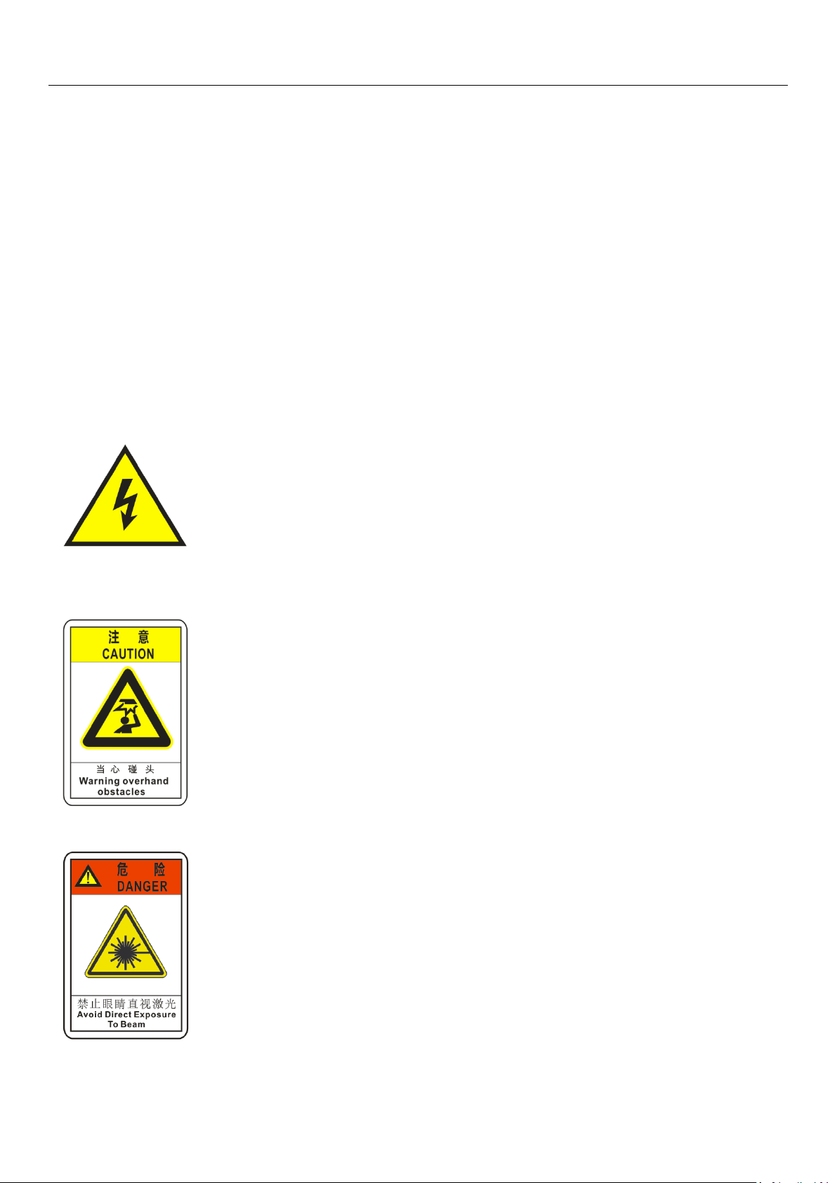
In the use of this device, please strictly comply with the requirements of the warning signs in the device!
WARNING!
Before using the High-precision Digital flexo Imager, please read carefully and understand the manual
content.Strictly follow all safety rules and regulations process while operating the equipment.Failure to
follow the safety precautions will not only damage the equipment but may even result in personal injury.
DANGER!
Unauthorized attempts of disassembling or alteration, and/or misuse, inappropriate operation of the
equipment hardware or modification of its circuitry may result in serious damage or malfunction to the
imager.
Caution Electricity!
Do not allow the body to come into contact with life current flowing parts of the
device.Put on anti-static gloves to prevent static or power surge when handling
with electronic or electrical components.Do not touch the power cord areas and
other electrical components with bare hands.Do not operate or turn on switch with
wet hands.
Overhead obstacle!
Equipment cover opening or closing, be carefulof head collision.
Do not look straight intothe laser beam!
Looking directly into the laserbeam is strictly prohibited. This would cause
damagesto your eyes.
7 / 55
Page 8
Overview
Beware of hand crush!
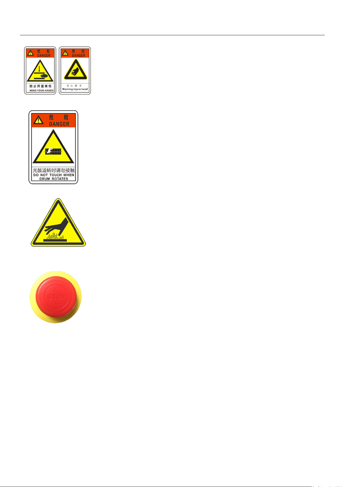
Please open or close the lead cover slowly, and avoid hands being crushed.
Drum is rotating! Do not touch!
Do not touch the drum while it is rotating the drum, it will cause injury!
Caution hot surface!
Do not touch the high temperature working part of equipment directly,
Emergency stop switch
Emergency stop switch is a safety measure function; when in an emergency
situation, where emergency stop switch is pressed to quickly get the drum stop
rotating.This switch is located on the side of the device top casing. Under
normal operation mode, make sure the emergency stop switch is disengaged or
released.
A. Rotate the switch in the direction of the arrow to dis-engage (working mode) the emergency
switch.
B. When the device appears abnormal, press the emergency stop switch, identify the cause and
problemhandling before reopening the emergency stop switch;
C. Emergency stop switch is only used when the equipment is found functioning abnormally.
Pleasedo not press it arbitrarily, so as not to cause unnecessary troubleto operator.
Note!
Emergency stop switch does not have the function of cutting off the current
power, make sure to turn off the power of the equipment before system
maintenance.
8 / 55
Page 9

Overview
2.6Safety Information
Electrical Safety
◆Equipment must be grounded effectively;
◆To protect the equipment and personal safety, it is recommended to install indoor lightning arresting rod;
◆All maintenance work on the equipment must be carried out with the power off;
◆When the equipment is working, do not touch the moving parts of the machine with your hands or fingers.
Mechanical safety
◆Only under the circumstances necessary to dismantle the device casing;
◆Be attention to the machinery operation, always wear gloves, tools and parts must be placed in an orderly
manner;
◆Do not perform any maintenance or modifications to the equipment system that is not authorized by CRON.
◆Do not place any foreign objects on the device;
◆In non-emergency situations, it is strictly prohibited to press the emergency stop button;
◆In the operation of mechanical parts, always wear gloves, so as to avoid rusting parts; tools and parts should
be placed in order;
◆ Avoid overhead collision during equipment operation.
Other safety aspects
◆This device is not intended to be used in an explosive or potentially explosive atmosphere.
◆Fireworks is prohibited near the occasion of this device;
◆Prevent water or other liquids from flowing into the interior of the device;
◆Debris, scrap or residue generated from the use of this equipment must be handled in accordance with the
laws and regulations of the hazardous material management authority in the country / region in which it is
used.
Policy of equipment requirements
◆To ensure that customer’s installation site, environment and conditions, are able to meet and comply to the
equipment operational requirements.
9 / 55
Page 10
Installation site and environment requirements
Device Model
Equipment Size
W(cm)
Equipment Size
L(cm)
Installation Space
W(cm)
Installation Space
L(cm)
HDI-600**
140
120
340
320
HDI-920**
170
130
370
330
HDI-1600**
232
115
430
315
L
W
Chapter 3: Installation Site and Environmental Requirements
—————————————————————————————————
3.1 Space requirement
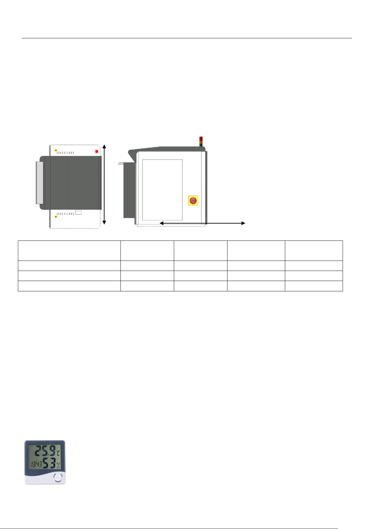
Refer to Table 3-1, given the size of the machine and consider the space needed, minimum distance
between wall and machine is 100cm, sizes of the room(space) needed for the machine installation can be
determined. It is also advisable to reserve some room space close to the installed machine for placement
of plates and media too.
Table 3-1: System equipment size and installation space required
3.2 Flooring & hallway access
Doors and corridors at the installation site must be wide enough ( ≧ 145cm) so that the machine can be
pushed into the room.Floor level should be maintained at ± 4mm. If installation to be done above ground
floor, this requires an industrial elevator that have can load more than 2000kg. After the machine is in
place, the machine requires leveling by using a level gauge.
3.3 Environmental requirement
Working room temperature: 18°C ---- 28°C
Environment humidity: 40% ---- 60%, Non-condensing
Air quality: should meet international quality standards, that is, API value is less than or equal to 100;
Other installations for indoor: Air-condition, Dehumidifier/humidifier, air purifier.
Picture 3-1: Multi-function environment measurement (Temperature Humidity Hygrometer Tester)
Page 11
Operation Instructions
Device Model
W(cm)
L(cm)
H(cm)
Weight(kg)
HDI-600**
170
136
140
850
HDI-920**
190
150
137
950
HDI-1600**
260
170
147
1600
Chapter 4: Offloading, Unboxing and Installing
—————————————————————————————————
4.1On-site conditions during offload handling
Customer needs to provide handling equipment and tools to ensure the safe handling of the machine to
the installation site.In the meantime, CRON engineers will assist with the handling and uncrating on site.
4.2Shipment packing
A High-precision Digital flexoImagerunit is usually packed in a wooden crate box for easy shipping and
handling. The following table lists the package sizes and weight of different models of HDI.
Table 4.1: Packing size and weight
4.3 Loading &unloading equipment
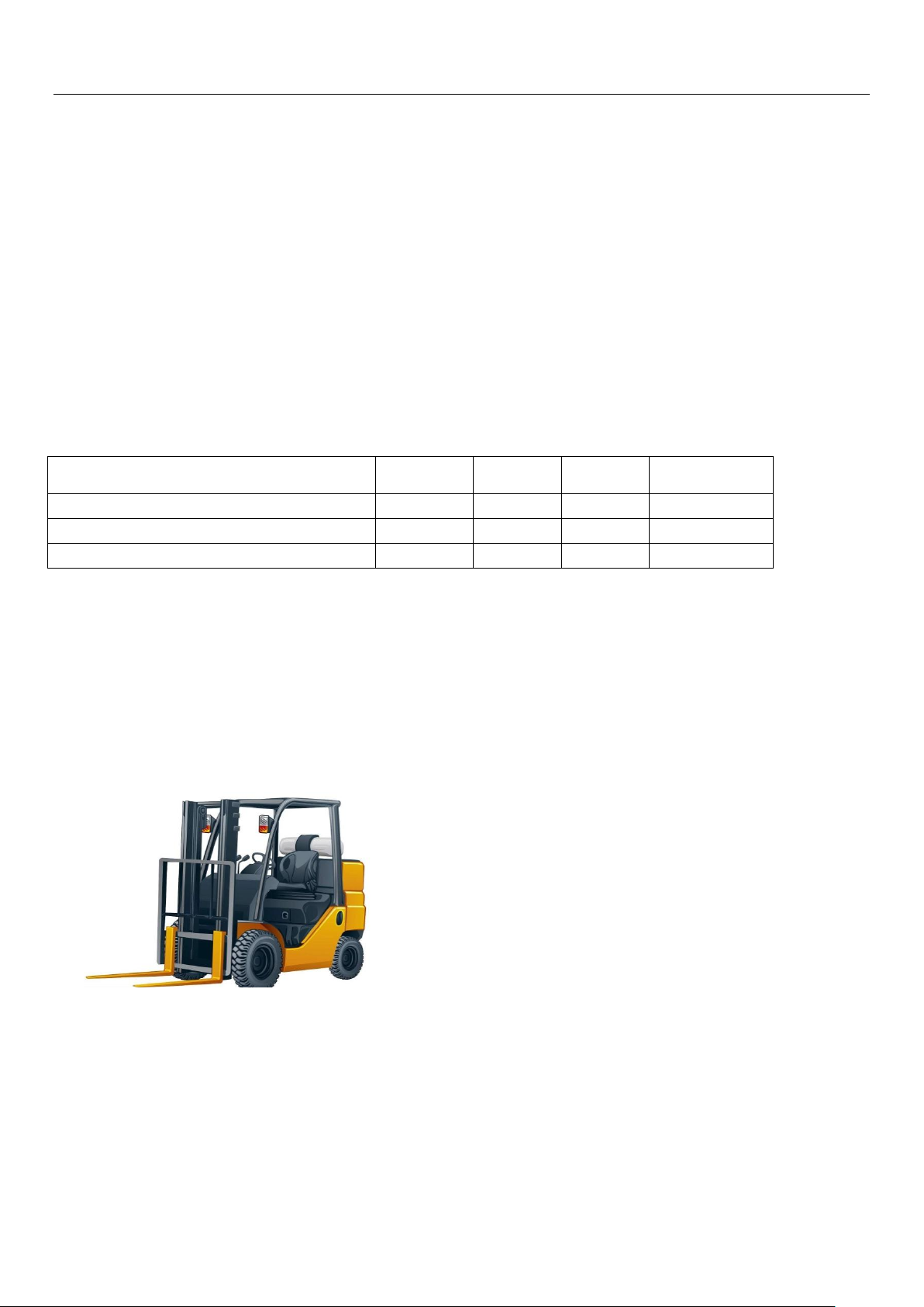
Customers must provide forklift or crane with minimum load-bearing for more than 2000kg. Forks length
must be more than 150cm. If necessary, lengthen the span of two forks according to the wooden box and
the structure of the machine to adjust to the corresponding width.
Picture 4-1: Forklift
4.4 Installation personnel
CRON advised customer to provide professional handling personnel to move the machine to the premises
of installation and unpack the crate, with CRON professionals work together on site.
Page 12
Operation Instructions
HDI-600
Uncrate the box
Remove accessories
Lifting & positioning
Remove aluminium foil
Device levelling
Remove fixing bracket
4.5Unboxing, fixing and installing
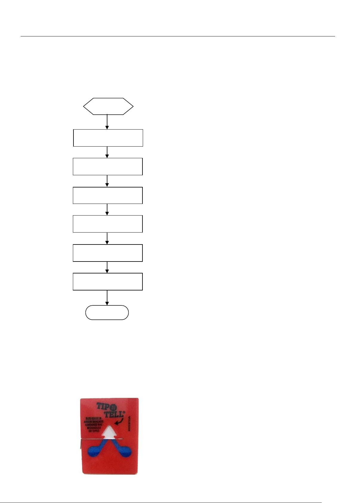
4.5.1 High-precision Digital flexo Imager unboxing flow chart:
4.5.2Unboxing preparation
First of all, check the crate box is intact, tilt indicator whether has any toner presence of overflow
beyond the guide line. Ifproblems are found, they should be documented and feedback to CRON
immediately.
Picture 4-2: Tilt indicator
12 / 55
Page 13
Operation Instructions
No
Description
Figure/Model
No.
Material/
Specification
Qty
Note
1
Wooden box pallet
Wood layers
1
2
Equipment
1
3
Wooden box side
panels
Wood layers
2 4
Wooden box end
panels
Wood layers
2
5
Wooden box cover
Wood layers
1
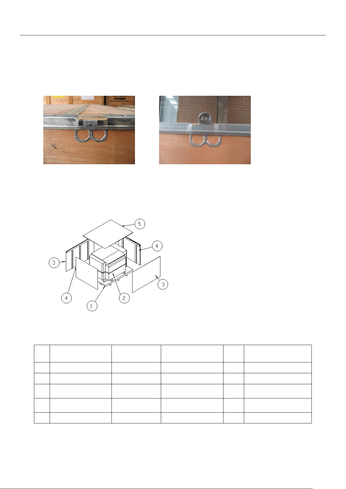
4.5.3 Uncrate the box:
Use long-nose pliers to loosen the wooden case lock;
A) locked stage B)unlocked stage
4.5.4 Follow the steps to remove the wooden box cover, side panels and pallet base(shown in Figure 3
and Table 1);
Figure 3: Panels removal instructions
Table 1:Wooden crate panels list
13 / 55
Page 14
Operation Instructions
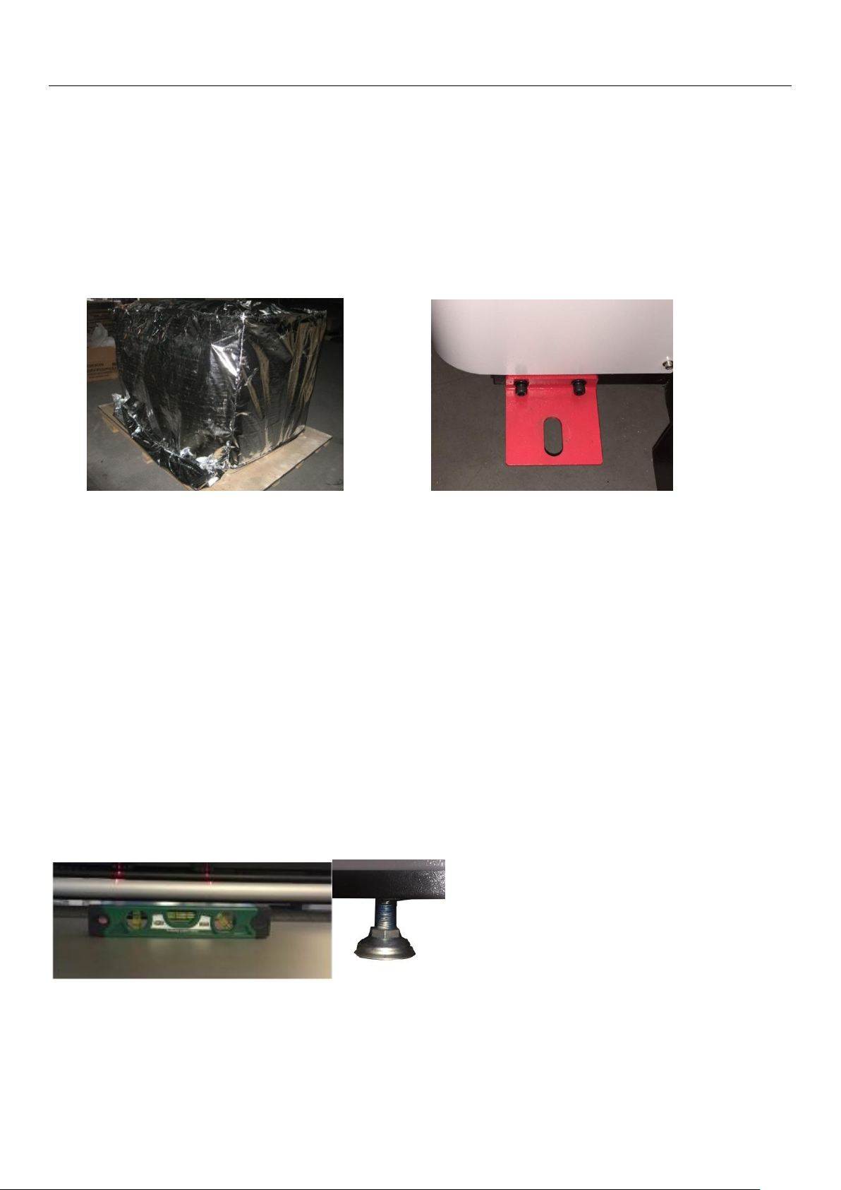
4.5.5Removal of aluminium foil:
Cut the foil bag at the bottom in circle, then remove foil bag (Figure 4).Be careful not to scratch the
equipment while cutting the foil bag.Then unscrew the hex screws 8-M6 * 10, unscrew the nut
4-M10,remove the fixing brackets(Figure 4);
Note: Depends on season and modes of transportation, method of packing could be done either
withwrapping bag, and/or aluminum foil bag. The description here refers of an aluminum foil bag as
an example;
Figure 4: Aluminium foil and equipment fixing brackets figures
4.5.6 Remove of bundled accessories:
Find the opening and remove of stretch film, remove the equipment spare parts and accessories and
keep it in a safe place for later use.
4.5.7Device lifting and positioning:
While using a forklift to lift up the HDI device, length of folds should be beyond the center gravity of the device,
and forks tips should be kept out of the wooden pallet base. Keep attention and maintain stable while shovel
and lifting the device. Moves the device to the installation location and carefully lower it down onto the ground.
4.5.8 Device level adjustment / power on
a)Adjust the device’s 3 support legs so that the legs are evenly weight down, and having the
transporting wheels levitated.At the same time adjust the overall level of device;
b) Connect the device power according to the power connection requirements;
14 / 55
Page 15
Operation Instructions
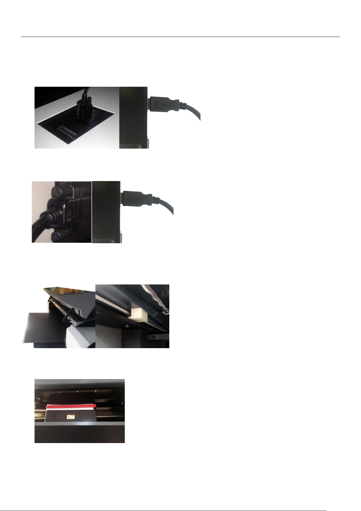
4.5.9Connecting USB communication cable to the computer
a) HDI-600** /HDI-920**uses a separate external USB cable to connect the device and the computer.
The cable is located above the right side of the housing, and it is fastened tight to ensure reliable
connection;
b)HDI-1600**using an external USB interface cable to connect device and computer, the cable is
located in the lower right side of the enclosure, and it is fastened to ensure reliable connection;
4.5.10 Removal of the device’s “scanning platform fixation bracket”:
a-1) HDI-600 ** / 920 ** Model Scanning Platform fixation bracket is located inside the device. When
removing, open the device upper cover and remove the limit screws;
a-2) Move the top cover forward, notice that the "scanning platform fixation bracket" (in RED color)
inside the right sideof the device;
15 / 55
Page 16
Operation Instructions
b-1)HDI-1600 ** Model’s scanning platform fixation bracket is located inside the device. After
removing the upper cover of the device, you can notice the scanning platform unit.
c) Use a hex wrench to remove the fixing screws of the "Scanning Platform Fixation Bracket" of the
device and pay special attention when removal; Handle with care and avoid scratches to the Encoder
Strip(gold color) that attached at the side of the panel along the guide rail.
4.5.11Putting back device covers
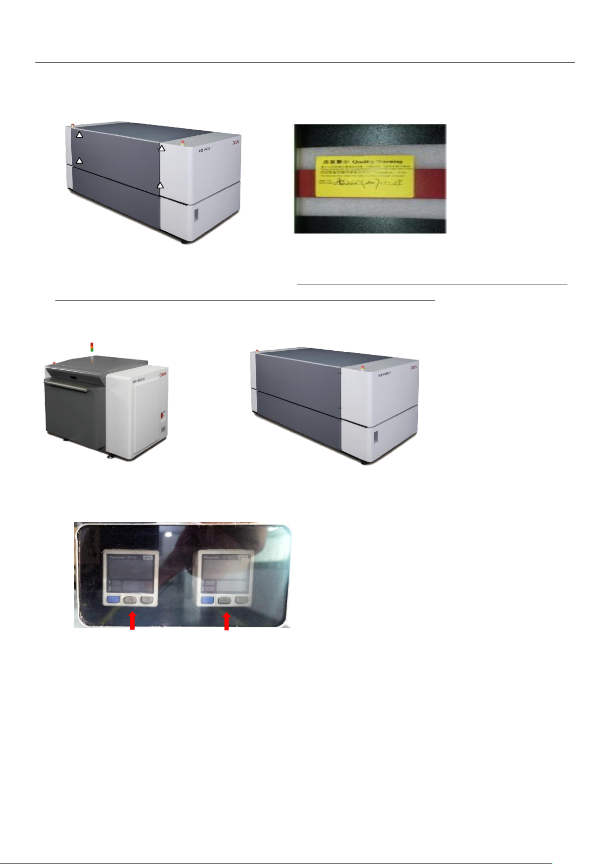
4.5.12Pressure window: through the pressure window, you can obtain current dedustingvacuum
pressure value, drum vacuum pressure value and the pressure sensor output status;
Dedusting vacuum Drum vacuum
16 / 55
Page 17
Operation Instructions
Chapter 5: Operation Instructions
—————————————————————————————————
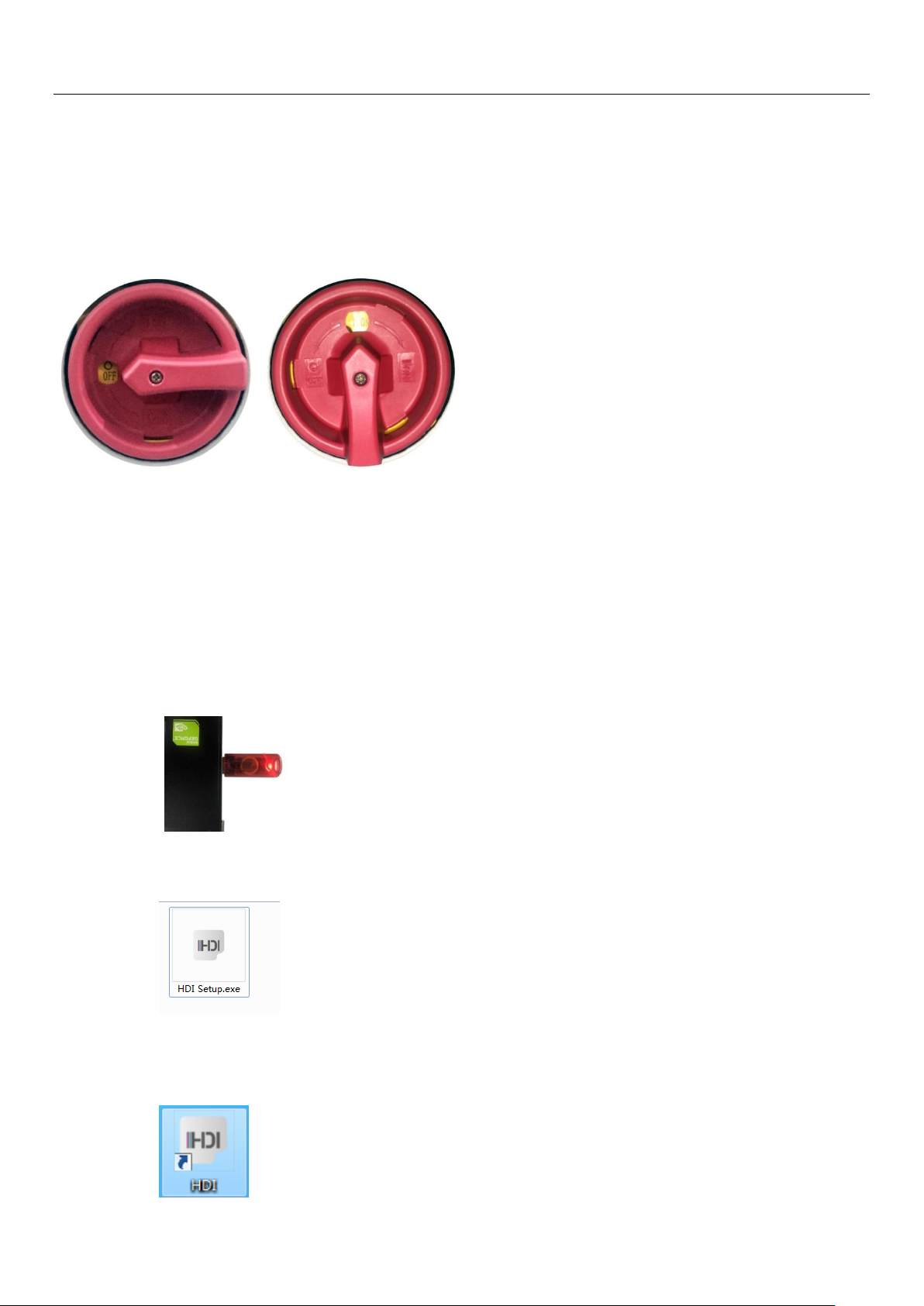
5.1 Turning on device
A) Open the circuit breaker(at the rear of the device) to the ON position. Then turn the cam switch to the
ON position to allow power supply access to the device.
5.2 Connecting to computer
Refer to 4.6.7, connect the computer USB port
5.3 Laboo-HDI installation & startup
5.3.1Connecting the Dongle and install LaBoo-HDI software
a) Remove the supplied dongle from the LaBoo software box and plug it into the USB port of the
computer;
b) Inserts theLaBoo software installation disk(provided in the Laboo software box) and insert it into
your computer's CD-ROM drive and run the "HDI Setup.exe" file;
c) Follows the software installation steps to install the LaBoosoftware and dongle driver.After
installation is completed successfully, the computer desktop will have the following icon shown as
below:
17 / 55
Page 18
Operation Instructions
Note: It is recommended to change the software installation directory to a non-system disk, such as D:\ drive.
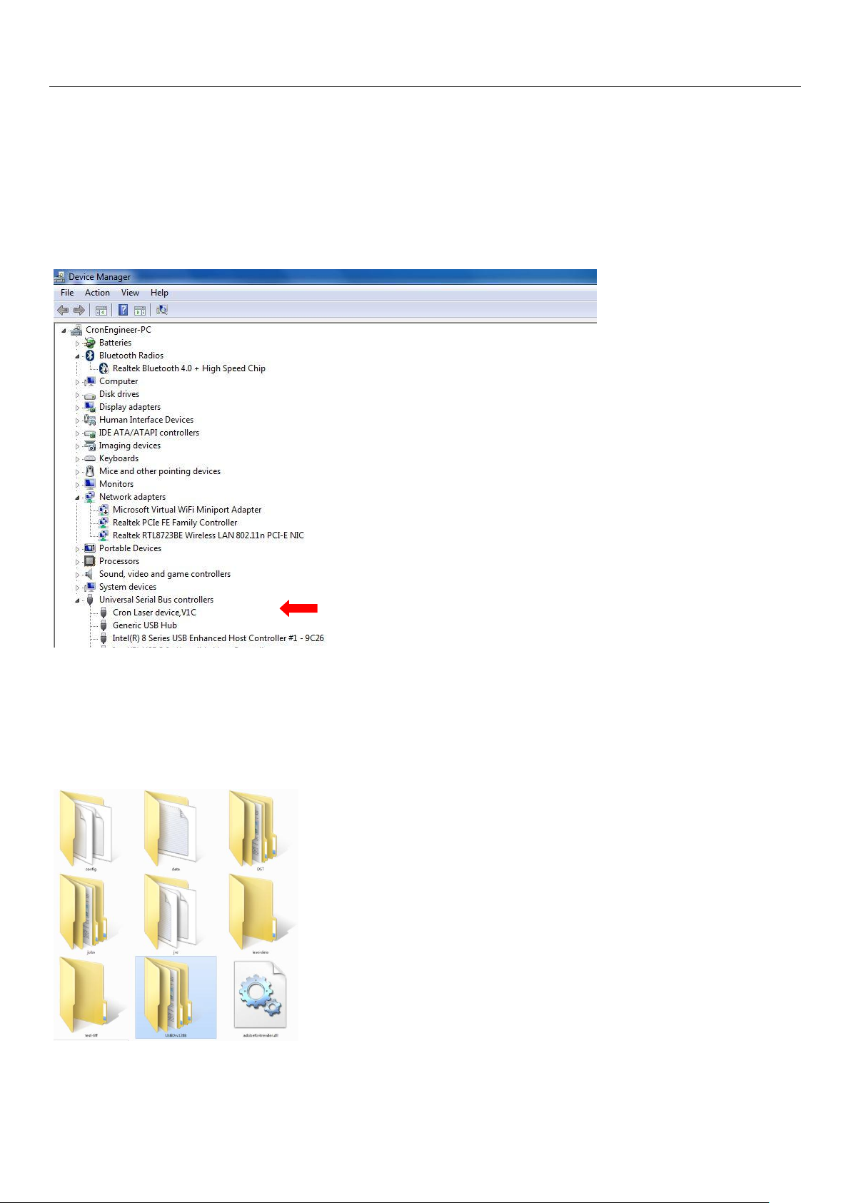
5.3.2Verify and making sure HDI device driver is installed correctly:
a) Under Windows Control Panel - Device Manager, confirmed that the HDI device driver has been
properly installed. The following hardware “CRON laser device, V1C” can be found under the
Universal Serial Bus controller.
b) If software installation incorrect, the software will not be able to establish connection to the device. In
this case, you need to manually install the HDI device driver by updating the with newer driver for the
Windows. Device driver files are stored in the LaBoosoftware root directory - "USBDrv128B" folder, please
manually update until the device driver is installed and shown in the Device Manager under the Universal
Serial Bus controller.
18 / 55
Page 19
Operation Instructions
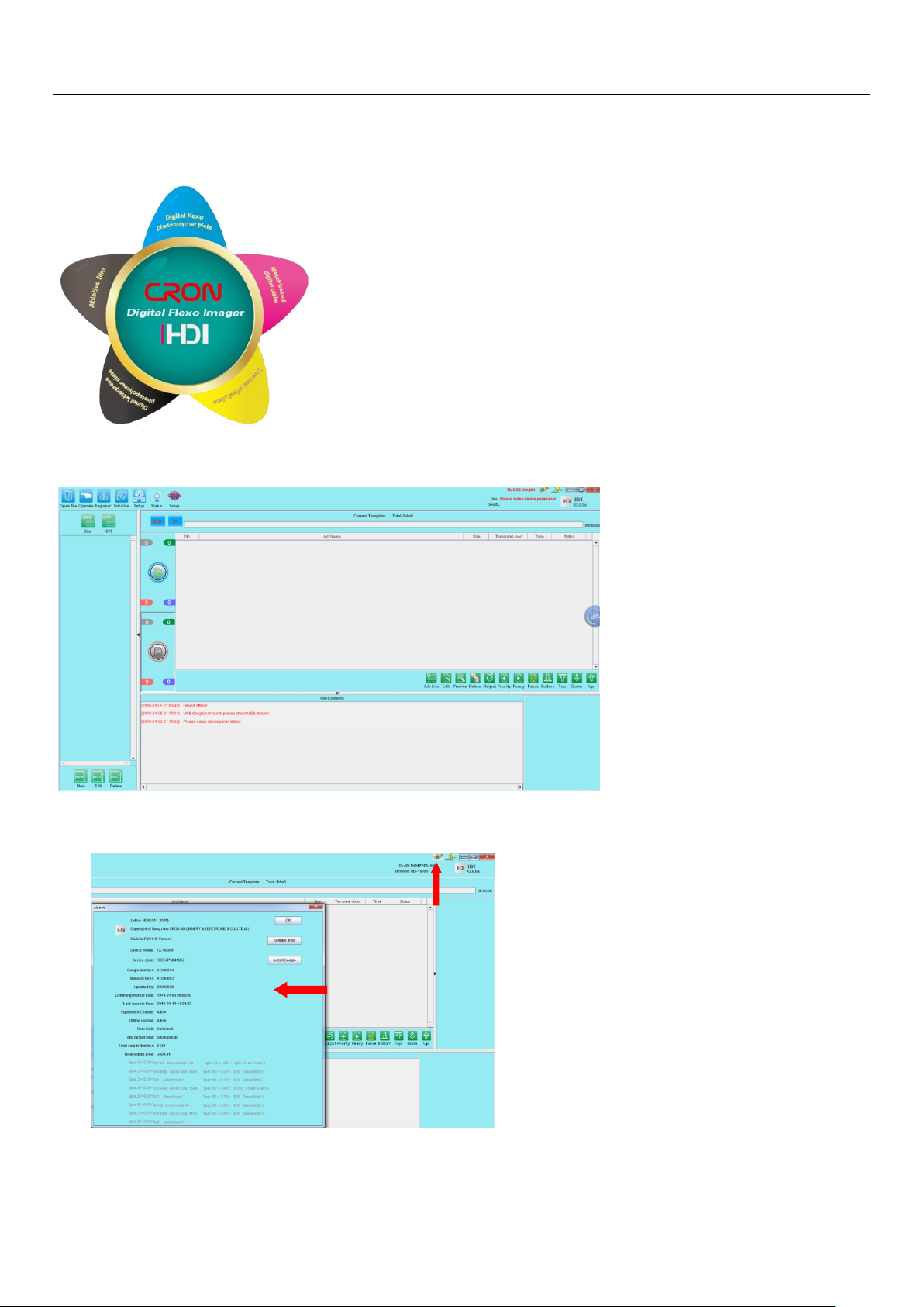
5.3.3 After LaBoo-HDI software successfully installed, double-click the icon of LaBoo-HDI software
shortcut on the desktop, the startup interface as shown below:
5.3.4After launching the LaBoo-HDI, below is the main interface of the software:
5.3.5 Confirm dongle installation and information: The dongle and device information can be obtained
through the dongle icon in the upper right corner of the software.
19 / 55
Page 20
Operation Instructions
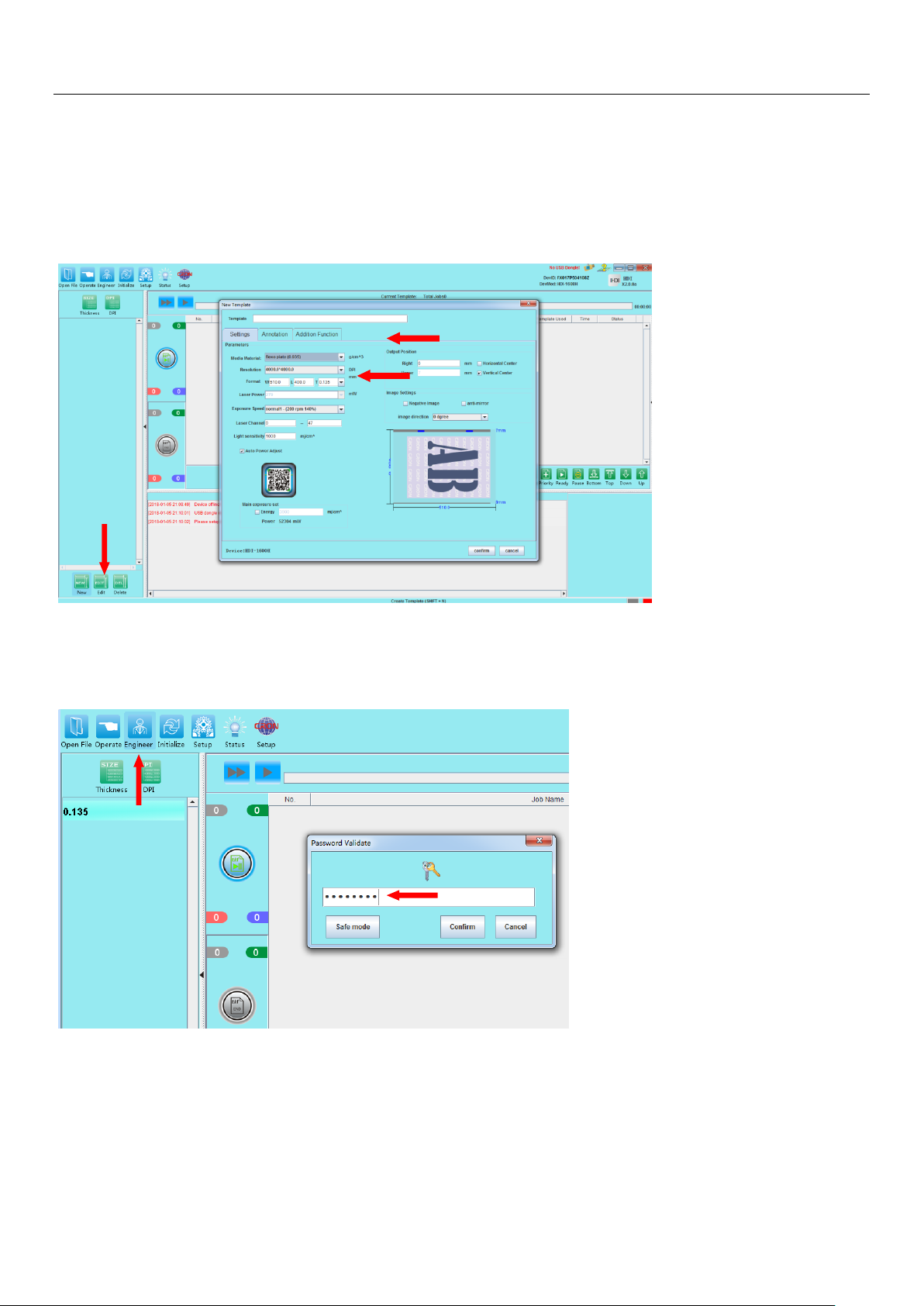
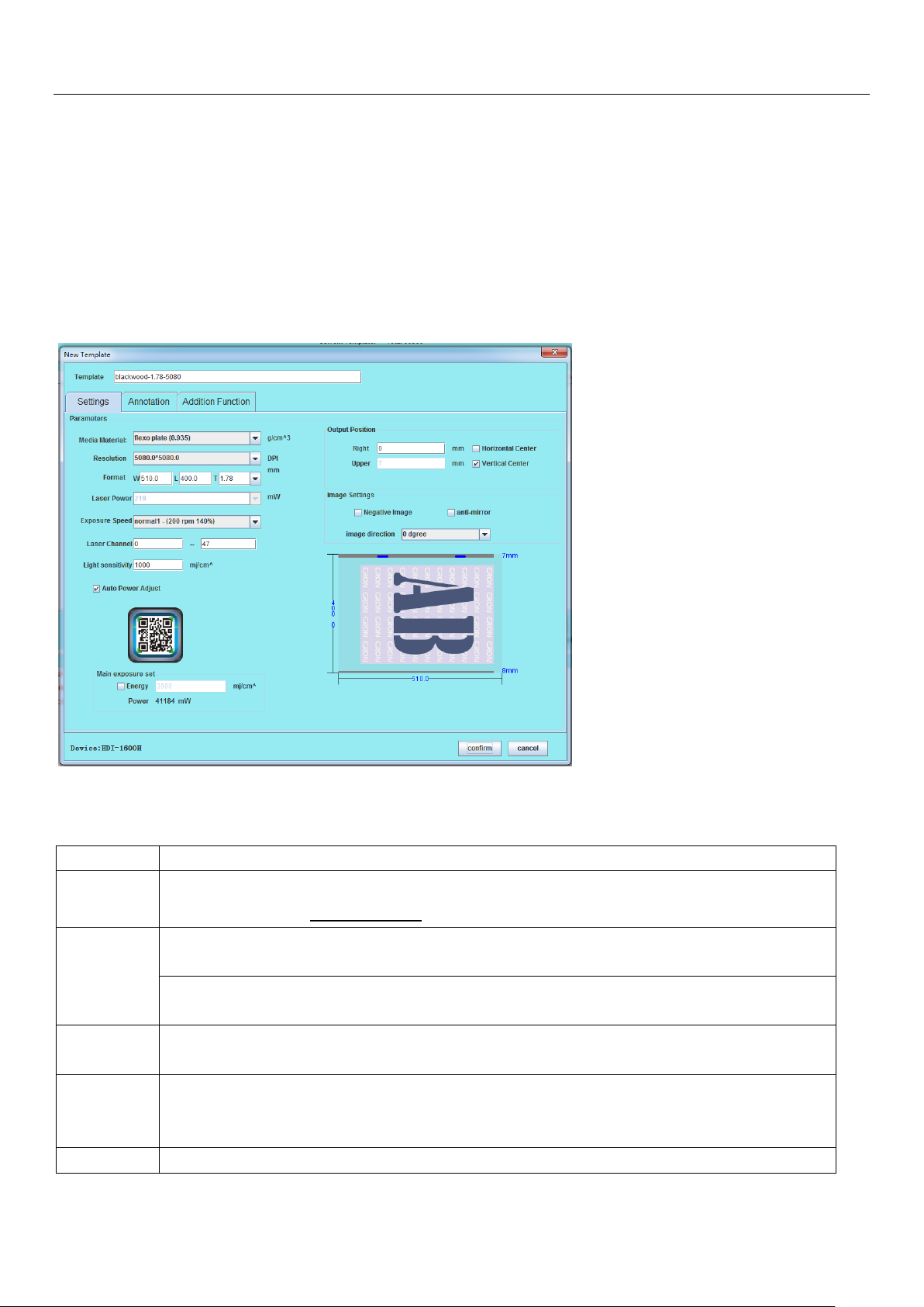
5.3.6 Newly installed software first need to setup the initial template, click the “New”green button (at
lower left) to create and setup an initial new template:
Setup a template size within the model specification allowable range, confirm "template name",
"media material", "resolution", "format", "laser power", "exposure speed" and other parameters, as
described in Section 5.4.1 - Table 5.1.
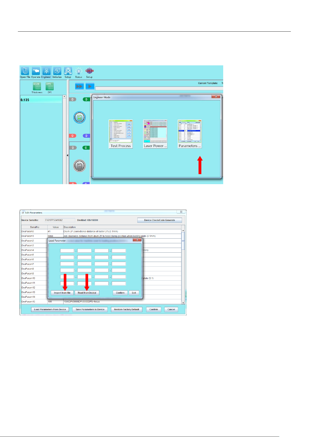
5.3.7 Click on the Engineer button to enter to software’s Engineer Mode. Enter the default
password "cron1234"when in the password field when prompted.
20 / 55
Page 21
Operation Instructions
5.3.8 Enter to the device parameter settings: After engineer mode password is entered, there will be a
pop-up windowswith 3 options prompted. Click on the right option “Parameters” button.
5.3.9To read in device parameters, there are 2 options available::
a) Import from file: Obtained one of the disk(Parameters disk) that bundled with device. Insert it into
the CD-ROM drvive, then clicks on “Import from file”, and browse for the file in the disk that named
with the device’s serial no. Select and confirmed to read in the parameter values from the file into
the LaBoo-HDI software.
b) Read from device:Click on this option to allow LaBoo-HDI software to read in (download) the
parameter values directly from the HDI device connected.
21 / 55
Page 22
Operation Instructions
Field
Description
Template
Set the template name; Recommended naming conventions: plate brand model - thickness resolution.Example: Flexo-1.78-5080
Media
Material
Set the material used in the template. Support materials: PS plate, film, flexo. (Different
model’s configuration, available material selection may be different).
Note: Material setting incorrect will cause out of focus, device jitter and other issues, including
affecting the imaging quality.
Resolution
Set the resolution for the template to work with.(Different model’s configuration, available
resolution may be different).
Format
Set the plate size of the jobs template. Size direction refers to the lower right
diagram.Thickness should be in accordance with the actual measurement. (Available largest
and smallest format depends on HDI model).
Laser Power
Laser power is set manually, in accordance with the energy needs of the plate, value should
5.4 Create work template
Once device’s parameter valueis correctly loaded into LaBoo-HDI software, you can proceed with the
software for further operation;
5.4.1 Create new job template: Click the "New Template" button to bring up the new template dialog
box. According to the actual work needs, setup a job template, in this case we have added a 510x400 PS
platetemplate for the operation; confirm setup once done to establish of a hot folder that can facilitate
subsequent jobs that relevant to this template settings.
Table 5.1:Term Explanation
22 / 55
Page 23
Operation Instructions
not exceed the factory default maximum power;
Note: If the Auto Power Adjust is checked, platemaking exposure is automatically adjusted
according to Light Sensitivity value entered. It is strongly recommended to choose this option.
Exposure
Speed
Exposure drum speed selection, in accordance with the actual production settings. Maximum
exposure speed is determined by the plate sensitivity, maximum laser power and drum speed
limit.
Laser
Channel
S series= maximum setting 0-31, H series= maximum setting 0-47.
Light
Sensitivity
The platemaking energy is determined by the plate characteristics, provided by the plate
supplier or by measurement.
Main
Exposure
Thisis an option selective component, only valid for devices with main exposure structure.
Output
Position
The output position can be adjusted during actual production. By default you may leave it
without any value adjustment.
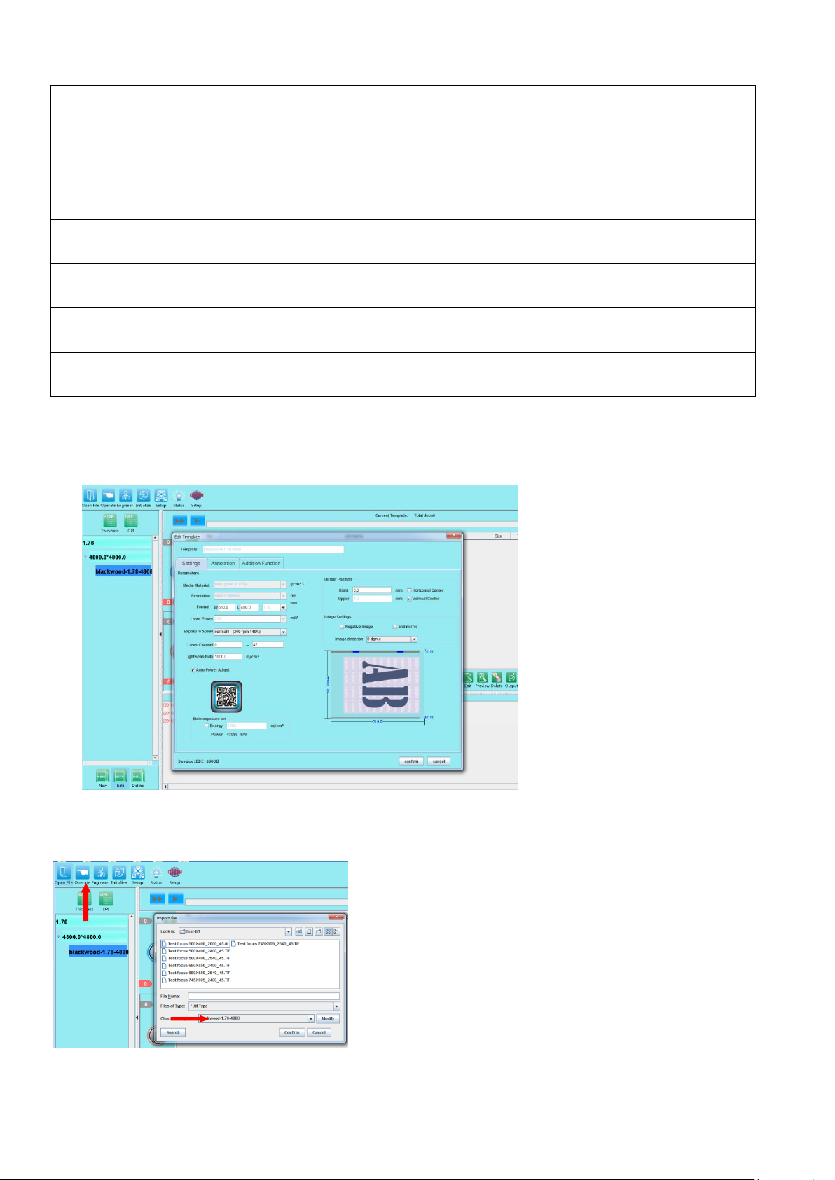
5.4.2 Editing a working template: After the working template is setup, you can edit the template again for
changes. When editing a template, the Template name, Media material, Resolution parameters arenot
allowed for changes.Other parameters are allowed for changes or adjustment.
5.4.2 Adding a TIFF file job: Click the "Open File" button, select the * .Tiff and * .PPG file jobs in the
corresponding directory, select the file to be used and the corresponding template below (ensure that the
parameters are the same).After confirmation, the file appears in the output list of the software.
23 / 55
Page 24

Operation Instructions
Note: Please refer to the Laboo-HDI "User's Manual" for detail software operation.
24 / 55
Page 25
Operation Instructions
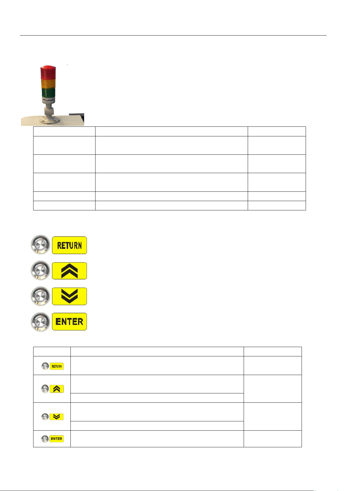
Label
Process Description
Status
Standby
The device is powered on, the PC LaBoo software is not
connected
Green + Red light
Connection
Connected to LaBoo software and acquired device
temperature successfully
Green light
Scan before loading
and unloading plate
LaBoo software output, loading and unloading in
operations
Yellow light
Scanning
Image scanning process
Yellow light
Error
Software error
Green + Red light
Label
Description
Status
Used to switch back to manually adjust the plate loading operation
during automatic plate loading
(Flashing effective)
Used to turn the drum counterclockwise slowly during manual
loading adjustment
(Flashing effective)
Avoid excessive adjustment causing tail clamp collision
Used to manually turn the drum slowly clockwise while
adjusting the plate
(Flashing effective)
Used for the next operation control in the plate loading process
Used for confirmation control during plate loading
(Flashing effective)
5.5 HDI-600 ** / HDI-900 ** Operation Description
Status (light) Indicator:
HDI-600**/920**Operation Keys Panel
25 / 55
Page 26
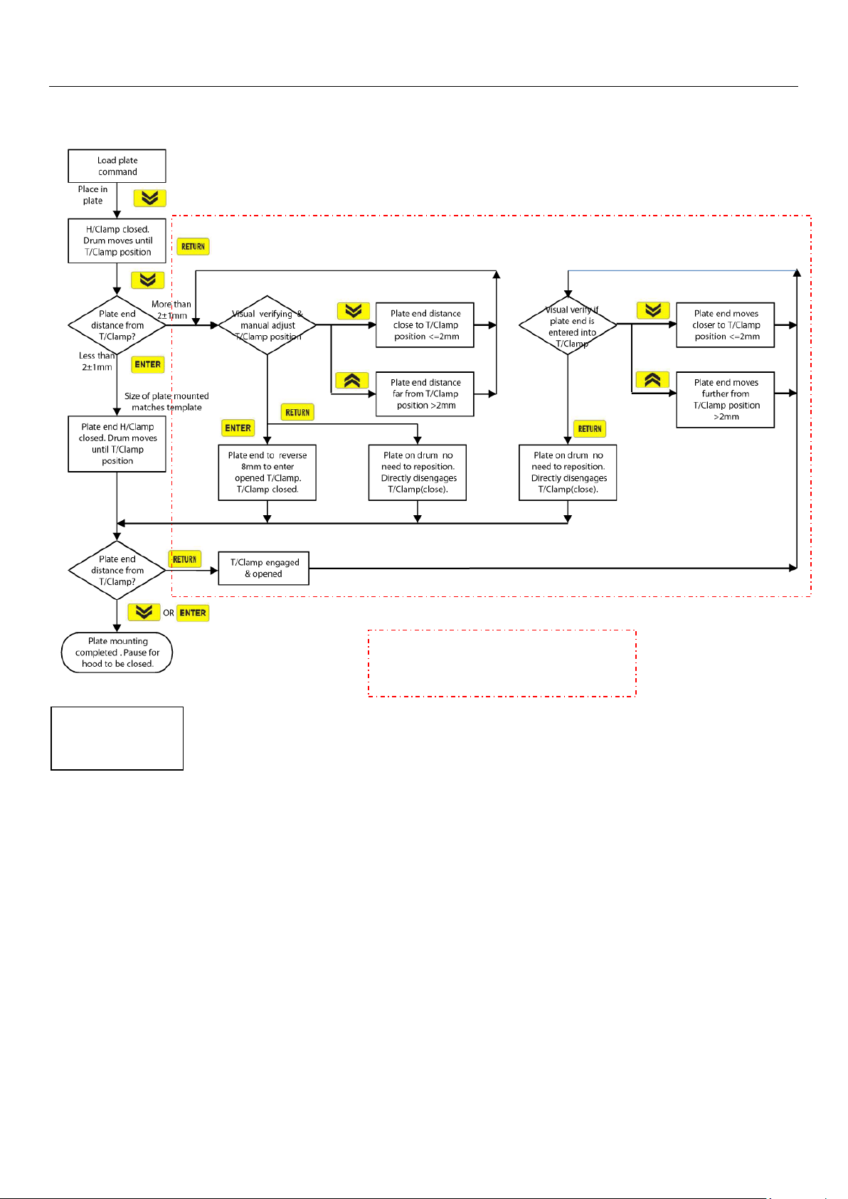
5.5.1 Loading process:
Manual adjustment for plate loading
operation (dotted line box)
Normal loading
operation
Operation Instructions
26 / 55
Page 27
Operation Instructions
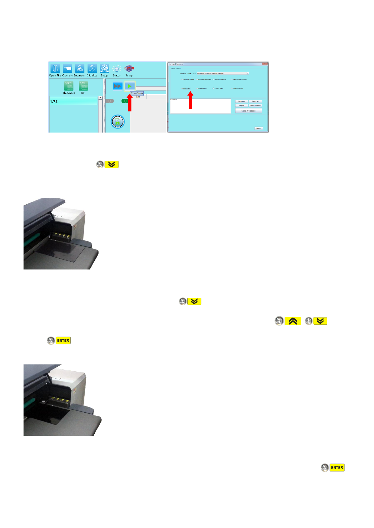
a) The device is ready for loading process either “Load Plate”command is executed under command
function, or job “Output”during plate imaging operation.
b) The drum is rotated to the loading position, the head clamp is opened and device is holding on for
next command, button light is flashing, plate stoperthe positioning column rises, waiting for
the next operation action.
c)Open the device’s upper cover and slide it back to open position, place in a plate with the size same
as the default template specified, align right to the anchor gauge, move in plate until plate front
aligned evenly with head clamp, press the button, head clamp on drum closed, drum starts
rotate and plate mounting on drum until it is close to Tail Clamp position. , ,
buttons lights are flashing, and awaiting to be pressed for operating action.
d) At this point, observe the end of the plate and the position of the Tail Clamp, and determine the
next proper action.
d-1)If Template(Tail Clamp) position correct, distance is about 2±1mm within, press the
27 / 55
Page 28
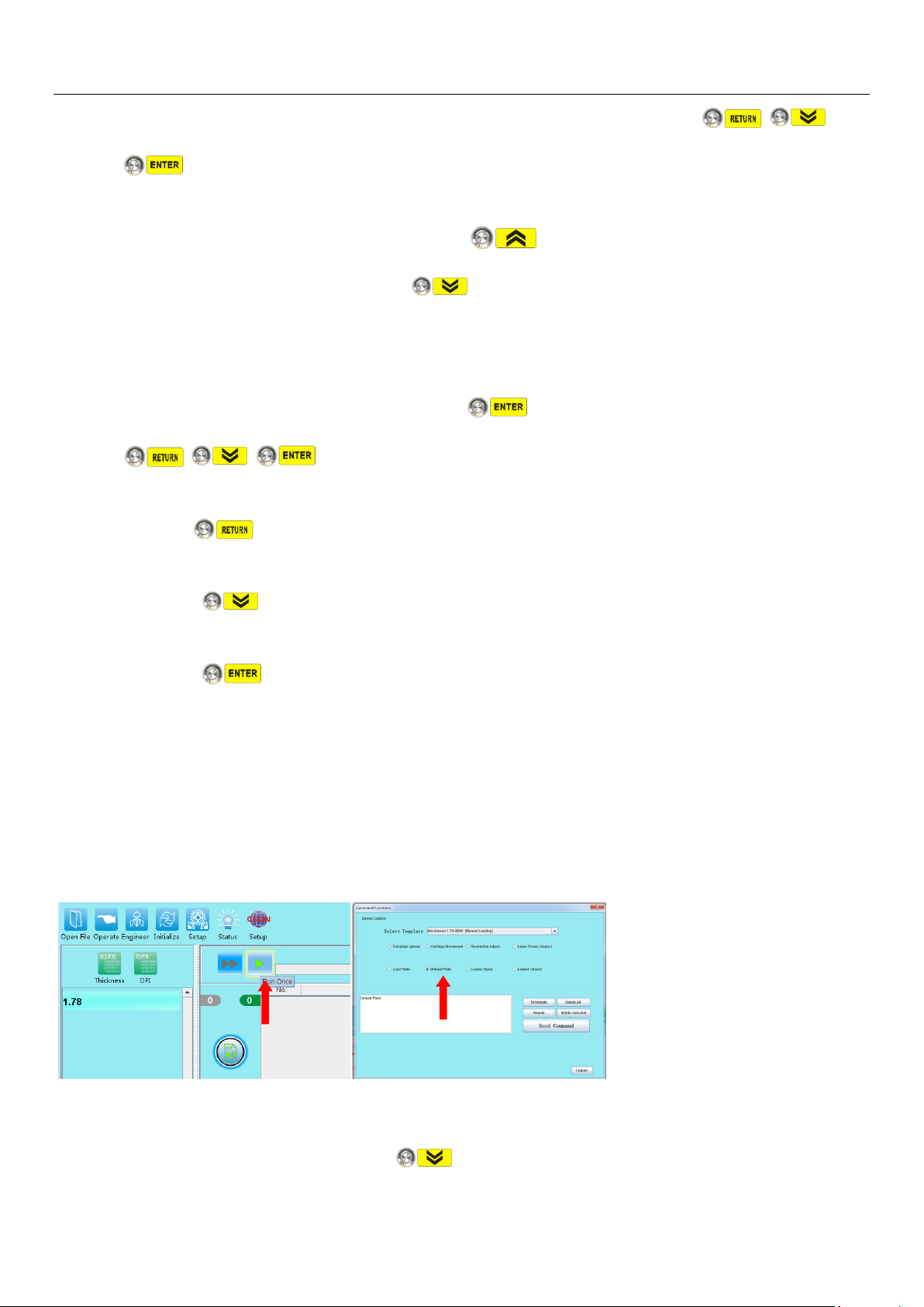
Operation Instructions
button to have the tail Clamp closed and clamped on the plate. At this point, , ,
buttons lights are flashing, and awaiting to be pressed for next operating action.
d-2)If found Tail Clamp position beyond or more than 2±1mm, you need to manually adjust the
Tail Clamp shaft position, either press on the button to have Drum rotates clockwise
2mm distance each time, or press on button, to have Drum rotates anti-clockwise 2mm
distance. This action is to allow the plate end on Drum to reposition closer to the Tail Clamp shaft
position in order for plate tail clamping.
Confirm that plate end entry to Tail Clamp shaft having depth is greater than 4mm and not getting
any obstruction by the Tail Clamp shaft, press button to close the Tail Clamp. At this point,
, , buttons lights are flashing, and awaiting to be pressed for next operating
action.
e) Press the button, device will returns to d) status,you can readjust the position of the Tail
Clamp, to avoid or correct previous manual adjustment deviation;
Press the button,to enter to Engineer adjustment mode. No further explanation needed
on this;
Press the button, to enter to Output operation mode. At this point, return the device’s
cover to its original closing position, the device has completed the plate mounting and clamping
process,and further proceed to automatic plateoutput process(imaging).
5.5.2 Plate unloading process:
a) Upon job “Output” process completed, or under the command process of “Unload Plate”, device
will enter into unloading procedures.
c) Open the device’s upper cover and slide it back to open position, at this point the device is ready
for plate unloading process. Plate end has already being released and away from Tail Clamp, and
Drum rotates to the unload position, button light is flashing, awaiting to be pressed for next
28 / 55
Page 29
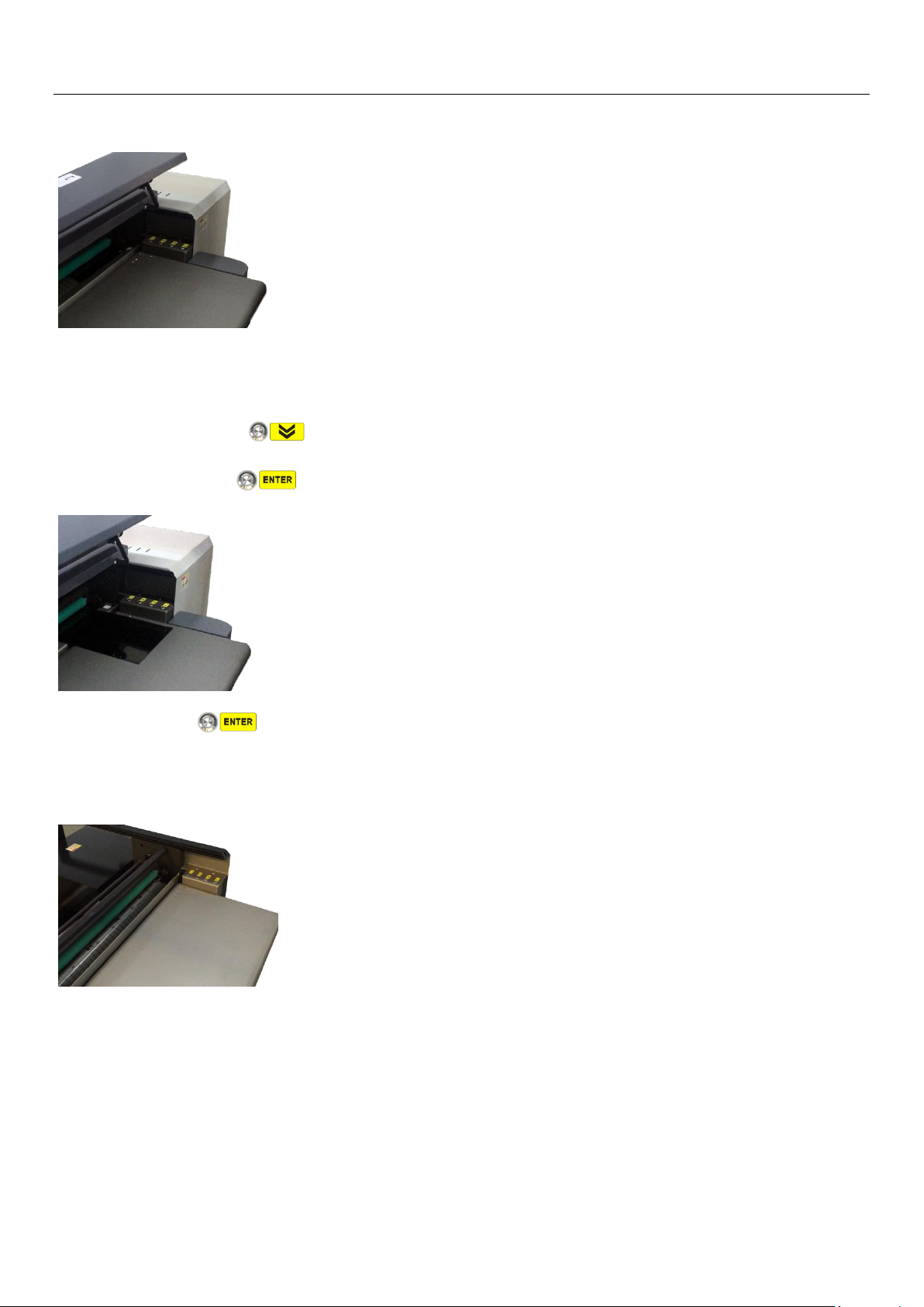
Operation Instructions
operating action.
d) Observe the plate on the Drum adsorption, if plate end not detach from Drum surface, you may
manually peel the plate end off from Drum surface, and gently drag the plate onto the platform
guide, press the button, device will automatic unload the whole plate until the Head
Clamp position, button light is flashing, and waiting to be pressed for next operating action.
e) Press the button, device’s Head Clamp open, plate must be removed before Head Clamp
closed back in 1 minute. Follow by plate stopper guide raise up, Drum repositions to the loading
position, this completes the unloading procedures and prepare for the next operations.
29 / 55
Page 30
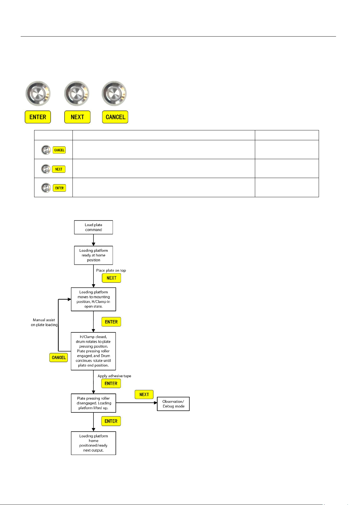
Operation Instructions
Label
Description
Status
Used to switch back to manual adjustment during automatic
loading
(Flashing effective)
For confirming the next step in the automatic loading process
(Flashing effective)
For validation control during automatic plate loading
(Flashing effective)
5.6HDI-1600 Plate Output:After clicking the job output command, the HDI device is ready for manual procedures
on plate output
HDI-1600 plate output buttons
5.6.1 Loading process:
30 / 55
Page 31
Operation Instructions
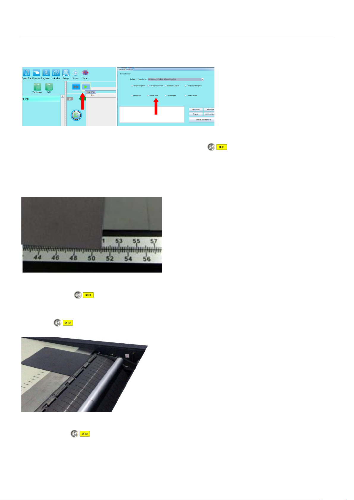
a) While in job “Output” command, or “Load Plate” command, the HDI device will proceeds with plate
loading procedures.
b) Device’s loading platform is ready at home position,the button’s light is flashing state.
You may place the plate on the loading platform now. (Make sure to place the correct plate size
according to template specification). Place and position the plate front to the loading platform edge,
and align it correctly to the right side anchorruler guide.
c) Press the button, loading platform will reposition and move downwardtouching the drum
surface(close to the plate mounting position, withthe Head Clampin opening state). At this time,
the button light is flashing, awaitingto be pressed for the next operating action.
d) Press the button, loading platform (with plate) will slightly move inner to the openedHead
Clamp, and follow by Head Clamp closing to have the front plate edge fastened. Drum vacuum will
31 / 55
Page 32
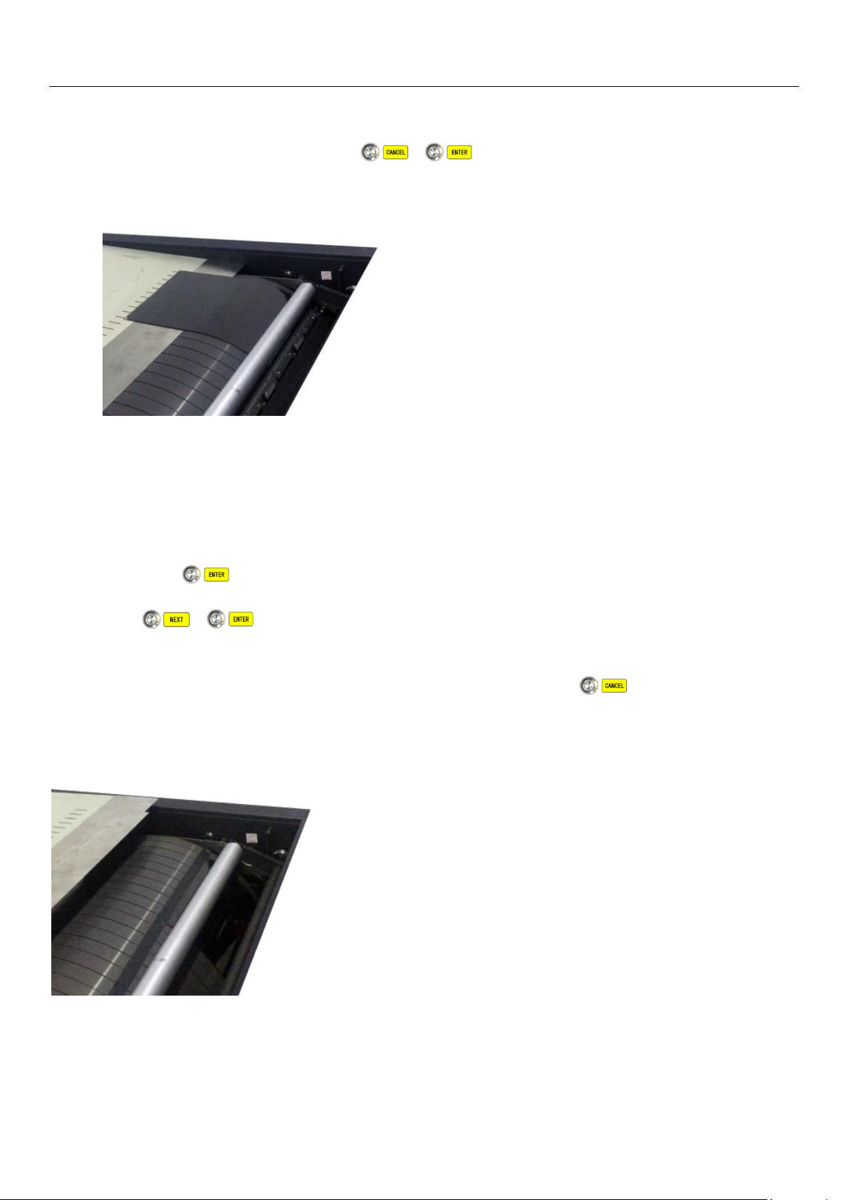
Operation Instructions
be activated, and drum first rotates to a position where plate pressing roller is engaged to press and
support on the plate before drum further continues to rotate until plate mounting comes to the
plate end position. At this time, both , buttons’lights are flashing, awaiting to be
pressed for next operating action.
e) Having plate mounting now come close to the plate end(plate tail), you may need to inspect and
observe the plate mounting position straightness and condition on drum before continue:
e-1)If plate mounted position is straight and correct, used 3M tape(or other high adhesive tapes)to
stick and patch on the plate tail edge . Note that the patch width should be greater than 5mm.
Press the button, loading platform will reverse and lift upward (drum uncover). At this time,
both , buttons’ lights are flashing, and awaiting to be pressed for next operating
action.
e-2) If found plate mounted positing is slant or incorrect, press the button, the HDI device
will return to “c)” state, which further allow user to manual adjust and correct the plate loading
and mounting position.
f) Once plate completely mounted and loading platform is reversed and lifted up from drum
surface(not close:
32 / 55
Page 33
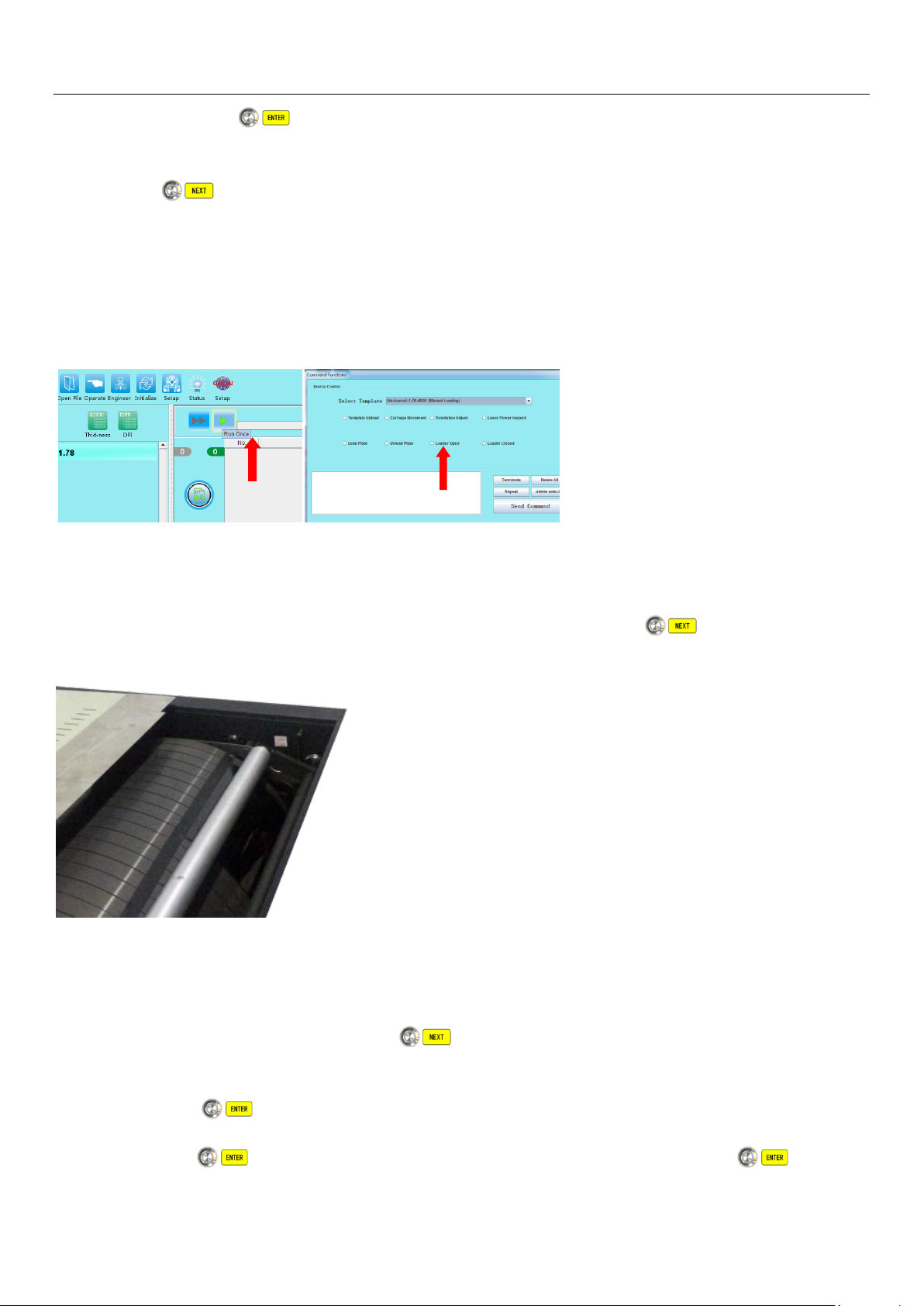
Operation Instructions
f-1) Press on the button, loading platform will return to its original home position, and HDI
device will starts output imaging.
f-2)If button is pressed,loading platform is remained unmoved after lifted up(drum
uncover), HDI device will proceeds with output imaging. Not advise for normal user operation.
5.6.2 Unloading process:
a) Once job “Output” process is completed or “Unload Plate” command is executed, the HDI device
will proceeds with plate unloading procedures.
b) HDI device will open and lower its loading platform onto drum surface, then move in closer to the
unloading position, where drum has positioned the plate end with the adhesive taped for easy
access by operator for next tape removal process, which is now the button’s light is
flashing, awaiting to be pressed for next operating action.
c) After removal of the adhesive tape on the plate end,observe plate on drum adsorption condition.
If found plate end mounted is still tight on drum surface, need to manually assist to peel off and
release plate end to be correctly position on the loading platform front edge for next unloading
process. Once confirmed, press the button for unloading,drum will rotates until the
Header Clamp release position(same time plate is transferred back to the loading platform).At this
time, the button’s light is flashing, awaiting to be pressed for next operating action.
d) Press the button, loading platform lifted up to the top position, again the button’s
33 / 55
Page 34

Operation Instructions
light is flashing, awaiting to be pressed for next operating action.
e) Press the button once again, loading platform will returned to its original home
position,remove plate from platform and process completes.
34 / 55
Page 35
Chapter 6: System Maintenance
For optimum performanceand productivity, regular maintenance and services are required
to be carried out on the device. The following are recommended maintenance cycles and
details to be noted (Inappropriate handling not according to recommendation may affect
device performance and even damage the machine).Maintenance is divided into routine
maintenance and regular maintenance. The device must to be operated under
standardenvironment requirement as stated according in the 《User Manual》.
Attention: Power must be turned off to ensure safety during maintenance.
Surface cleaning manners and precautions:
While cleaning device surface, first used a vacuum cleaner to clean dusts on the machine
casings, seams and accumulated dusts on plate loading platform.
If the indoor air is dry and clean, and the machine is often being cleaned, just use dry cloth is
wipe and remove the dust from the surface;
For thoroughly cleaning, wipe with a damp cloth mixed with mild cleanser and clean with a
damp cloth with detergent until it is cleaned and dried.
System Maintenance
Attention: Do not spill or leak water or detergent into the device, this could
causehazardous to operator or damage the machine.
Important: Strongly recommended that the following maintenance should be carried out by a trained
engineer or under the direction of a CRON qualified engineer.
6.1Device internal cleaning & inspection procedures
6.1.1Drum surface cleaning: After certain period of usage, plate pressing roller (mounting roller) and
drum surface will have accumulation of dusts and abrasions, that could cause damageson plate surface,
and/or affect the surface flatness during plate loading or mounting, it is necessary to clean up both the
roller and drum surface at any time if found dusty;
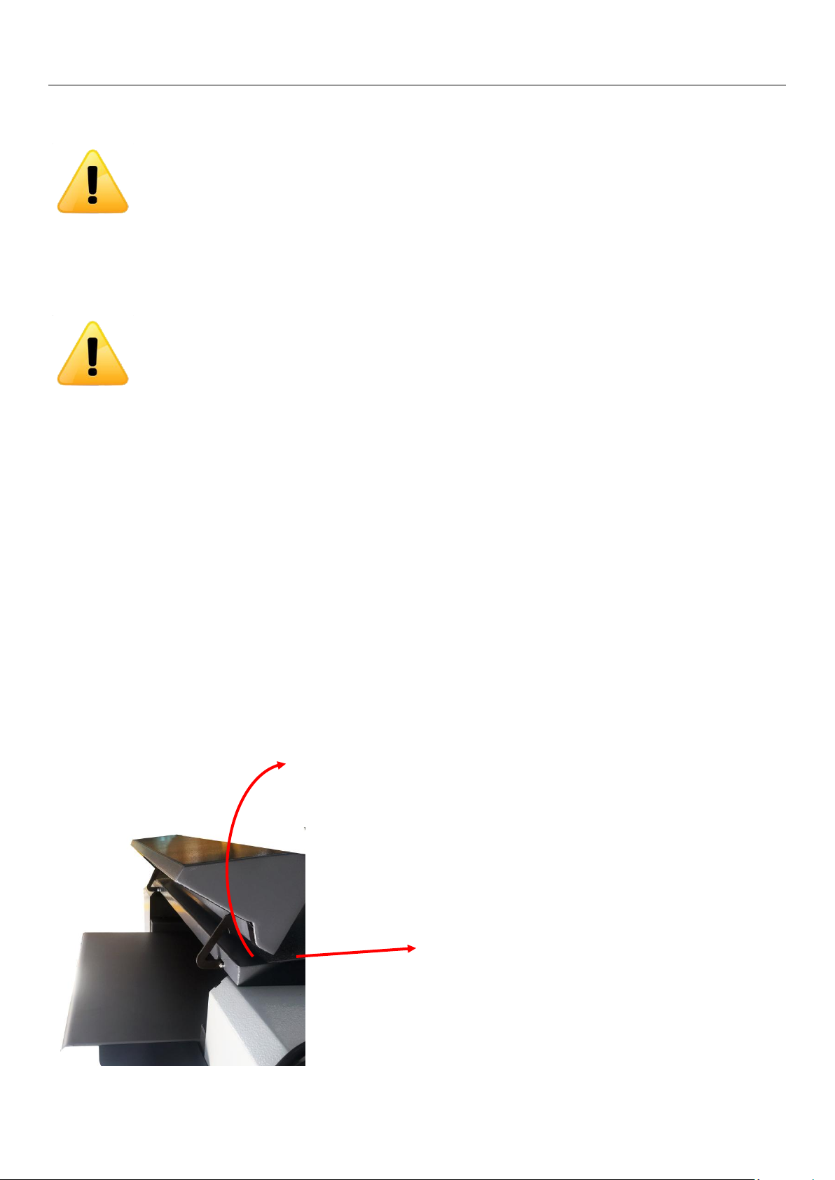
a) For HDI600/HDI920 series, flip open the front cover of the device, and slide the whole hood
backward to rear of device until its limit position. Front upper drum section is now fully visible,
you can observe the plate pressing roller (mounting roller) and drum surface conditions and its
mechanism components, please use dry cloth to clean and wipe these area if found dusty.
Page 36
System Maintenance
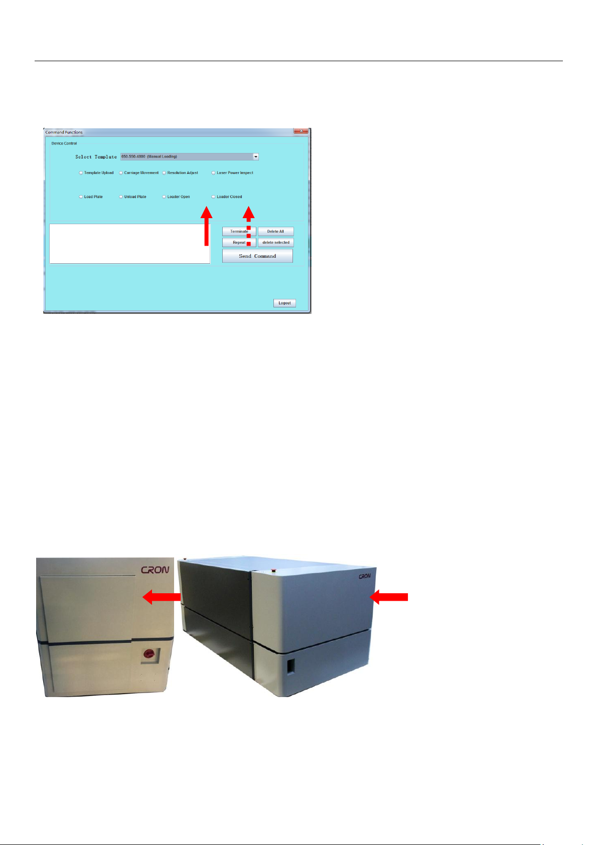
b) For HDI-1600, in the LaBoo Software, use the command functions “Open Platform”and “Close
Platform” to open or close the device top plate loading platform, you may to see and observe the
plate pressing roller (mounting roller) and drum surface conditions and its mechanism
components, please use dry cloth to clean and wipe these area if found dusty.
6.1.2Lens cleaning: After long period of usage, even its dust removal module, front lens sections are
parts that could get dust accumulates, and could affect laser power, focus efficiencies
during operation, and therefore this need regular cleaning maintenance;
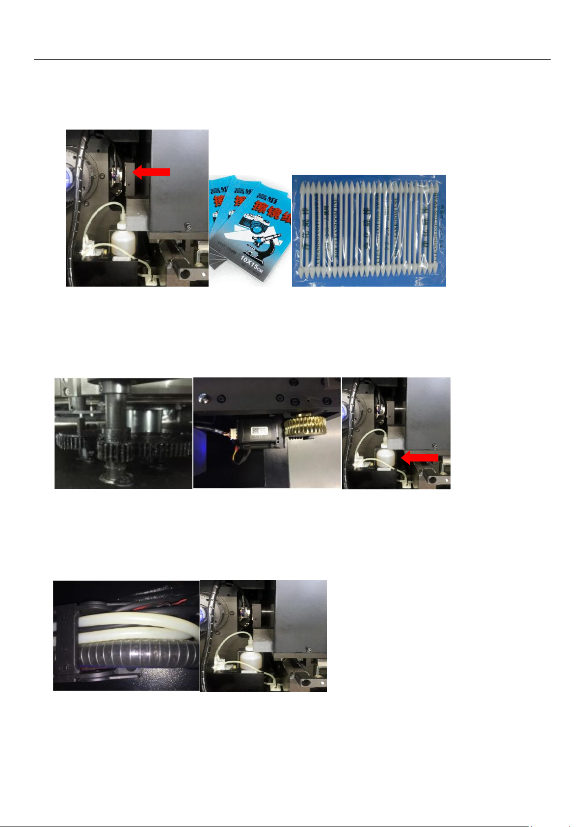
a) For HDI-600/HDI-920 series, open the right side service access cover of the device ,
you can observe and access Optical Power sensor and the optical lens section for
cleaning;
b) For HDI-1600, open the upper right side of the device casing cover, you can observe
and access Optical Power sensor and the optical lens section for cleaning; however
when opening the casing, be carefully of the Emergency Switch cable connection that
attaches to the casing. Avoid pulling and not to break the cable line and damage the
switch.
36 / 55
Page 37
System Maintenance
c) Manually move the scanning platform to the most outer side, dismantle the dust
removal module(remove itsscrew located on upper side) in order to access to the lens.
Clean the lens with special dust-free cotton bud or glass/mirror wiping paper;
6.1.3 Regularly lubricants level check: Equipment lack of oil could easily get rusted, causing overloaded
and other mechanical problem.Please check/inspect gears structure regularly (eg: hood sliding gears,
plate loading rocker gears), linear bearing rail, guide raillubrication conditions and guide rail oil
container level;
6.1.4 Regularly inspection on pipelines: Aging pipelines (air flow/vacuum/pressure) can cause damage,
pressure leakage and other problems, that can affect the proper operation of the device. Please inspect
the device internal pipelines for any defectiveness, crack or fragmented.If necessary, do replace the
affected pipes such as moisture depleting pipe, vacuum pipeetc;
37 / 55
Page 38
System Maintenance
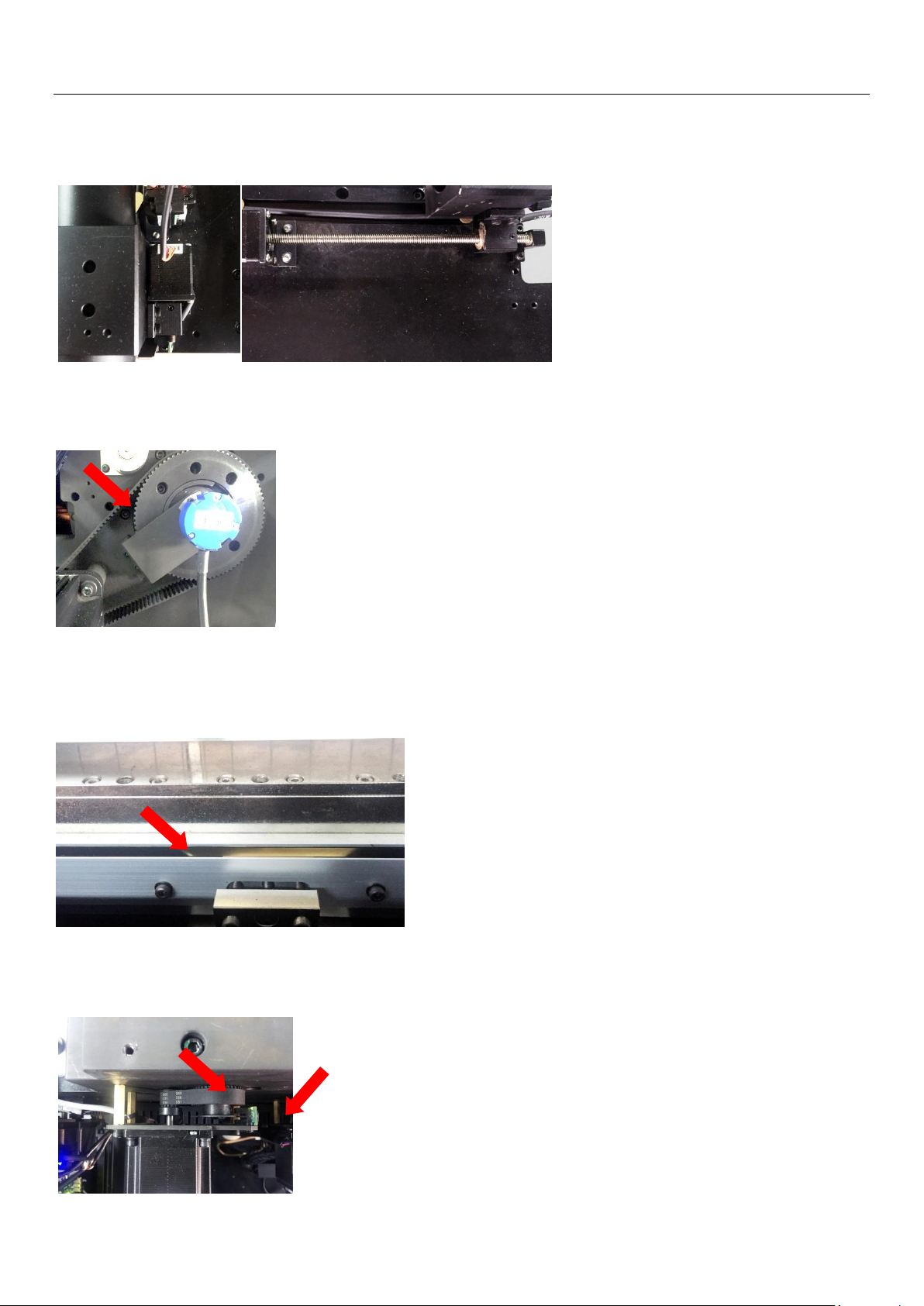
6.1.5 Check the scanning platform side screw, worknut lubrication and pitch cleanliness.
Regularly top up lubricating oil, such as worknut pitch worn off(loose pitch) , replace the
lead screw’s worknut.
6.1.6 Check the drum motor timing belt tightness and wear & tear conditions, if necessary, adjust the
timing belt tightness or replace the timing belt if found fatigue.
6.1.7 Check the linear servo system encoder strip cleanliness, remove or wipe dust or stains with dry
cotton cloth gently. Strictly prohibit the use of alcohol, acetone and other liquids while wiping the
encoder strip, as this will damage the encoder’s marks coating;
6.1.8 Check the stepping motors, timing belts and related sensorsfor any fatigue conditions or dust,
timely cleaning on these parts, replace parts if found defective of fatigue.
38 / 55
Page 39
System Maintenance
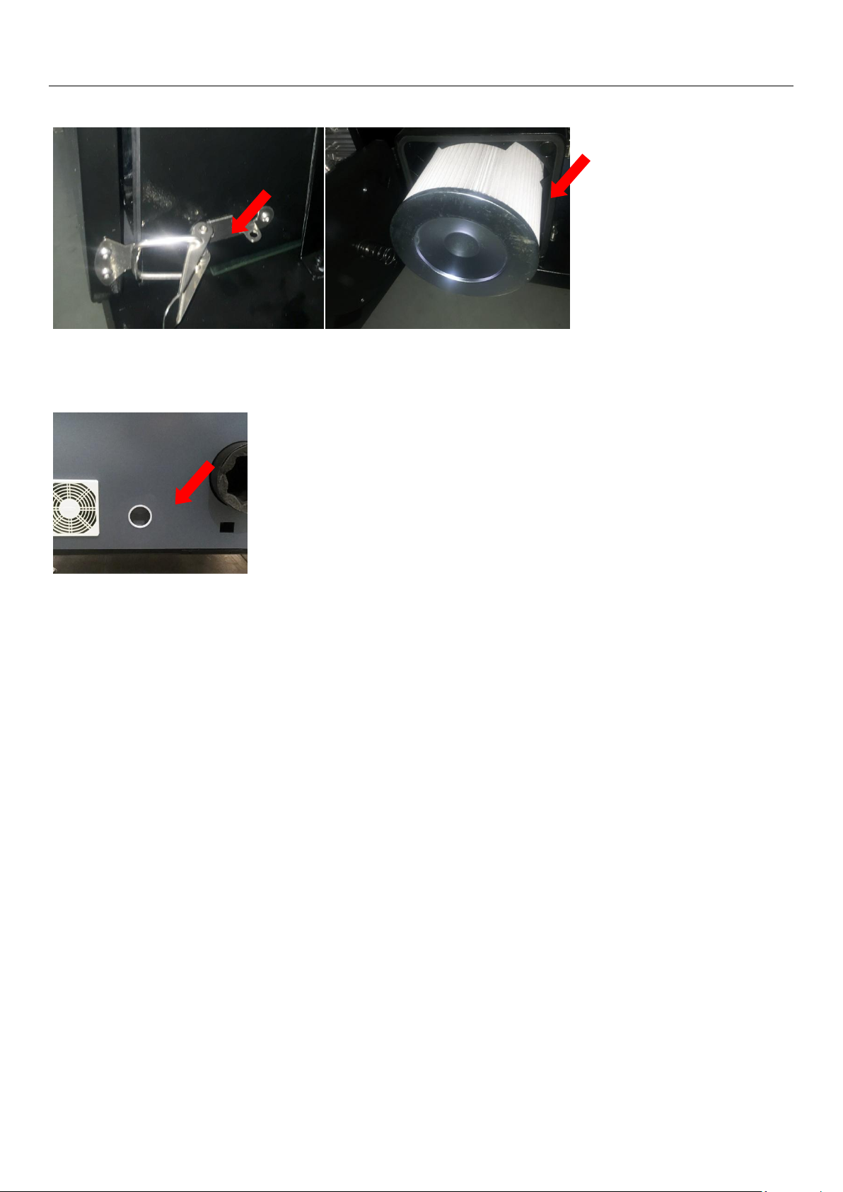
6.1.9 Remove the HDI device front lower casing, open the built-in vacuum cleaner(dedusting unit) to
access to the filter. Clean or replace the filter core from time to time.
6.1.10 Inspect the cooling system unit:Coolant level can be observed through the round window shown
below. Make sure coolant liquid level in the coolant tank must always maintain its fluid at 1/3 level
(or more).
39 / 55
Page 40
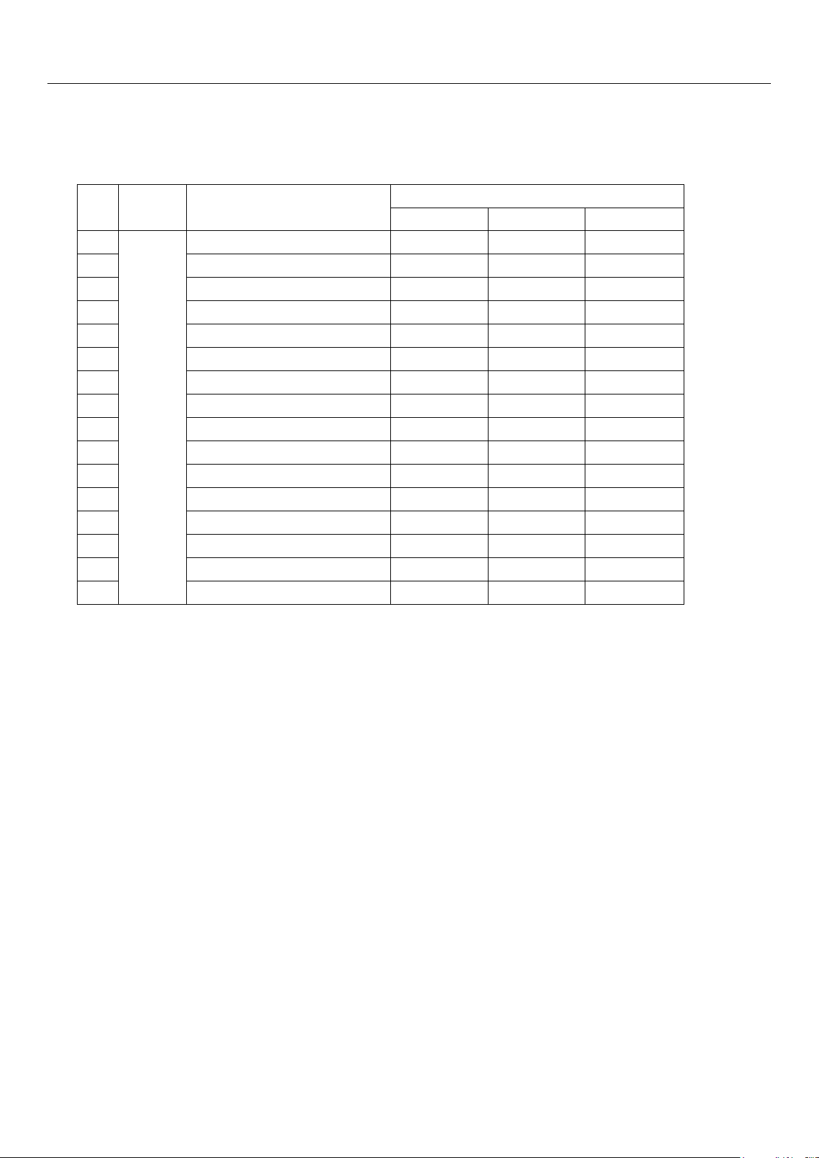
6.2 Daily Maintenance
No
Attribute
MaintenanceItems
Maintenance Cycle
Inspection
Cleanin
Replacement
1
Routine Maintenance
H/Clamp torsion springs
40000 imp
---- ----
2
Lens/Optical Sensor cleaning
1-2 weeks
2 weeks
----
3
Front guide rail lubrication
12months
----
24months
4
Focus/Zooming mechanism lubrication
3months
6months
12months
5
Plate pressing/mounting roller
1 months
3months
----
6
Internal dedusting filter
3months
6months
9months
7
Drum motor timing belt
3months
6months
12months
8
H/Clamp shaft pressing
9 months
--- ---
9
T/Clamp shaft pressing
9months
--- ---
10
Focus-Zoom lead screw/worknut
9 months
---
36months
11
All stepping motor timing belts
12months
---- ----
12
All stepping motor H/P sensor
12months
---- ----
13
Coolant liquid
6months
----
27months
14
Linear servo encoder strip cleaning
6months
12months
----
HDI Device daily maintenance itemize list
System Maintenance
Note 1: Recommended schedule undertake that the device is established in accordance of the
standard environment as stated in the User's GuideManual.
NOTE 2: Linear servo system encoder strip cleaning strictly prohibit the use of alcohol, acetone and
other liquids. Use only dry cotton for cleaning/wiping.
Note 3: Items that has more than 1 condition will base on which ever first condition comes first.
40 / 55
Page 41
Abnormal Problems Analysis and Handling
No.
Error Message.
Handling suggestion
1
Image size is smaller than plate size, job output is
stopped.
Click “allow large plate with smaller image size output”
under system parameters setting menu.
2
Job size is bigger than plate size, cannot be output,
please adjust parameters .
Check job size and reset parameters.
3
Original file is deleted, cannot be moved .
This file is deleted, try open another file.
4
Error on read device parameters.
Please retry again or contact engineer.
5
Dongle is abnormal! Please re-plug dongle .
Check if dongle is properly plugged or contact engineer.
6
Template name cannot contain:“' " : | ? * \\ /<>”.
Choose other letters.
7
Invalid enter!
Choose other letters.
8
Cannot open Tiff file
Please confirm TIFF file format.
9
Setup is not complete!
Some of parameters are not correct.
10
Please stop Hotfolder first.
Tick off in front of template name.
11
Hotfolder is already in use!
Change another hot folder.
12
Template already exists!
Change to another template name.
13
Incorrect resolution, cannot output.
Tiff resolution is not same as current template.
14
Image file is damaged.
Check if image file format is correct.
15
There is no passed usage record, update failed!
Contact engineer.
16
Parameters are not for this machine, cannot
complete parameter read, this is for machine:***
Check machine serial.
17
Plate format is over limit. Delete unused plate format
and try again.
Plate format max. is 32.
18
Parameters are not correct. Device cannot
be operational.
Check device parameters or contact engineer.
19
Device is not power on or hardware
cannot support software.
Please update software or contact engineer.
20
Parameters are not correct. Device cannot be
operational.
Check device parameters or contact engineer.
21
Device is not power on or hardware cannot support
software.
Please update software or contact engineer.
Chapter 7: Abnormal Problems Analysis and Handling
Attention!
Before proceeds for HDI device inspection and hardware handling, please wait for at least 5
minutes after power turned off to avoid electrical shock.
Device inspection, diagnostic, handling and replacement of parts components should be only
conducted by well trained and qualified technical personnel appointed by CRON.
Technical personnel involve in diagnostic and troubleshooting works should remove all metal
items from body before carry out the works. Use the insulating tools to avoid electrical shock
and precautions of injury.
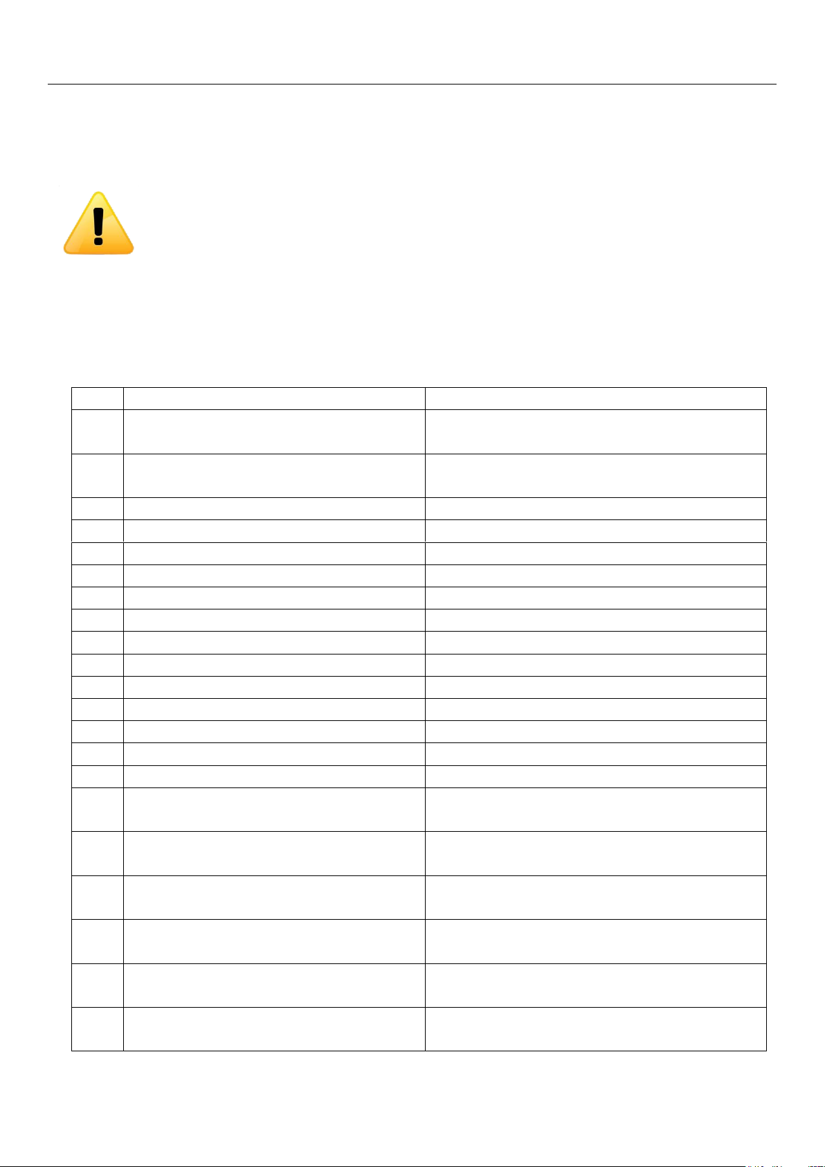
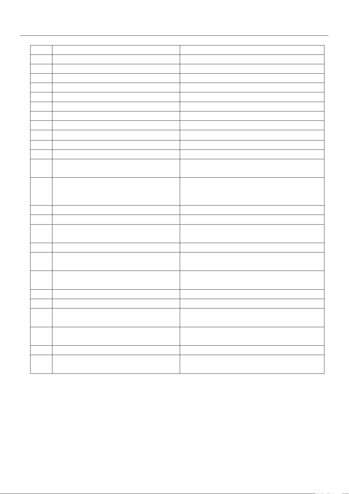
7.1 Error message and handling suggestions
Table 7-1LaBoo error information and handling suggestions
Page 42

Consumables Parts and Spare Parts
No.
Error Message.
Handling suggestion
22
Please clean lens
Do resolution adjustment and follow instructions to clean
lens.
23
Cannot find dongle.
Check dongle.
24
Command execute failed!
Do not send this command under current status
25
Laser box temperature abnormal, cannot output!
current is:** degree,shall be 15-35 degree.
Turn off machine and use air-con to change temperature or
Contact engineer
26
Device temperature abnormal, cannot output!
Current is:** degree, shall be 10-35 degree.
Turn off machine and use air-con to change temperature
27
Reset clock failed!
Contact engineer
28
Output reaches limit! Contact engineer .
Contact dealer immediately
29
Software authorized limit is less than 500 times,
Please contact dealer!
Contact dealer immediately
30
Software authorized output is up to date, output is
topped. Please contact dealer!
Contact dealer immediately
31
Laser power lock error channel:***.
Enter laser adjust program and test laser power
32
Laser power range is not correct, suggest to
change ** to ** .
Follow the message to change parameters
33
Read device parameters failed!maybe version is
not correct
Read device parameters again or contact engineer!
34
Reset without engineer .
Contact engineer.
35
Please adjust the focus.
Check and start.
36
NO dongle!
Ensure dongle is plugged-in and drive is correctlyinstalled.
37
Use preview under stand-by status!
Cancel “continuous output"and try again
38
Command is not allowed under current status.
Finish current status and try again.
39
Software limit is nearly up-to-date.
Contact dealer immediately.
40
Laser power test parameters setting is not correct,
suggest to decrease levels or increase value of
each level!
Reduce levels or contact engineer.
41
Device will change format, please confirm plates on
loading tray are removed!
Ensure plate size is correct or stack is ok.
42
Cannot locate system required memory
Restart computer or reinstall OS
43
USB communication failed. Make sure to install
correct USB drive or contact engineer
Check if USB drive is correct. Check is USB port is normal
or change another computer
44
Cannot connect to Autoloader!
Ensure autoloader is powered on and cables are connected
45
Drum speed is not stable
Check CTP power supply, emergency stop, top cover
protect or Contact engineer
46
Drum cannot reach required speed!
Check CTP power supply, emergency stop, top cover
protect or Contact engineer
47
Drum start abnormal!
Check CTP power supply or Contact engineer
42 / 55
Page 43
Consumables Parts and Spare Parts
No.
Error Message.
Handling suggestion
48
Tail clamp adjust failed.
Please clean air slot on drum or Contact engineer
49
Tail clamp position is over limit, please check.
Please clean air slot on drum or Contact engineer
50
Plate size is over limit (drum cannot be balanced!).
Please clean balance block sensor or Contact engineer
51
Vacuum pressure is not correct.
Check air pump filter
52
Tail clamp failed, please turn off and check.
Please clean air slot on drum or Contact engineer
53
Main board control process start failed.
Restart CTP and PC or Contact engineer
54
Autoloader control process start failed.
Restart autoloader or Contact engineer
55
Plate loading last time abnormal!
Check plate stack
56
Laser cannot be started!
Open laser adjust program or Contact engineer
57
Cannot connect to autoloader.
Check power supply and cable connection
58
Drum cannot stop!
Contact engineer
59
Already plate on drum.
Check if plate on drum or do #105 test command or contact
engineer
60
Cannot connect to device! Make sure device is
power on and USB cable is connected or contact
engineer!
Check power supply, USB connection and USB drive.
61
Cannot read parameter file information!
Check if parameter file is correct
62
Device ID validate failed.
Read device ID again or contact engineer
63
Temperature compensation is not completed
(overtime)!
Check platform focus compensation movement or contact
engineer.
64
Main control board data flow is abnormal.
Restart PC or Contact engineer
65
When start record process, data in main control
board memory is not ready!
Restart PC or Contact engineer
66
Cannot start record process, platform position limit
signal is not correct.
Check platform position limit sensor or Contact engineer
67
Cannot find this error code information.
Contact engineer
68
Image format is unknown.
Check if dongle is plugged in
69
File size ## * ## is over template setting, cannot
open this file.
Setup another template or adjust current one
70
Resolution is not same, as template setting, cannot
open this file!
Setup another template or adjust current one
71
Parameter is over limit!
Check parameter or Contact engineer
72
Software version is too old, cannot read parameter!
Please update software.
Update current software
43 / 55
Page 44
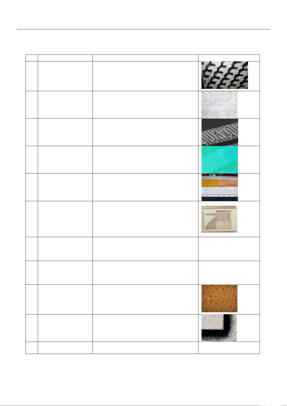
Consumables Parts and Spare Parts
No
Problem description
Cause analysis
Typical results
1
Dots shoulder thin, low
run length, dots holding
not strong
1.Main exposure time too short
2.Plate washing time too long
3.Imaging power too low
4.Dot compensation too low
5.Back exposure time insufficient
2
Scanning lines/bandings
1. Imaging power too low
2.Out of focus
3.lens dirty/dusty
4.Plate thickness value incorrect
3
Image not sharp
Main exposure time too long
4
Negative inversion
low/not visible
1.Main exposure time too long
2.Plate washing time too short
5
Dots relief too shallow
1.Back exposure time too long
2.Plate washing time insufficient
6
Thin lines loss/bent
1.Main exposure time insufficient
2.Back exposure time too short
3.Drying time insufficient
4.Brush pressure too much
5.Plate washing time too long
7
Plate surface uneven
1.Drying time insufficient
2.Plate washing time too long
3.Bottom of plate dirty
4.Plate storage inappropriate
8
Plate surface sticky
1.UVC exposure insufficient
2.Plate washed not thoroughly
3.Washing/Spraying insufficient
4.Drying time too short
9
Plate surface
wrinkle/bumps
1. Main exposure time insufficient
2.Plate washing time too long
3. Washing/Spraying insufficient, or wash solvent
not drawn dry
4.Plate handling not appropriate
10
Plate fracture
1.Curing time too long
2.Sticky treating time too long
3.Plate being oxidized
11
Length deviation
1.Perimeter correction incorrect
2.Plate layout direction different
7.2
Common plate-making problems and causes
Table 7-2: Common plate-making problems and causes
44 / 55
Page 45
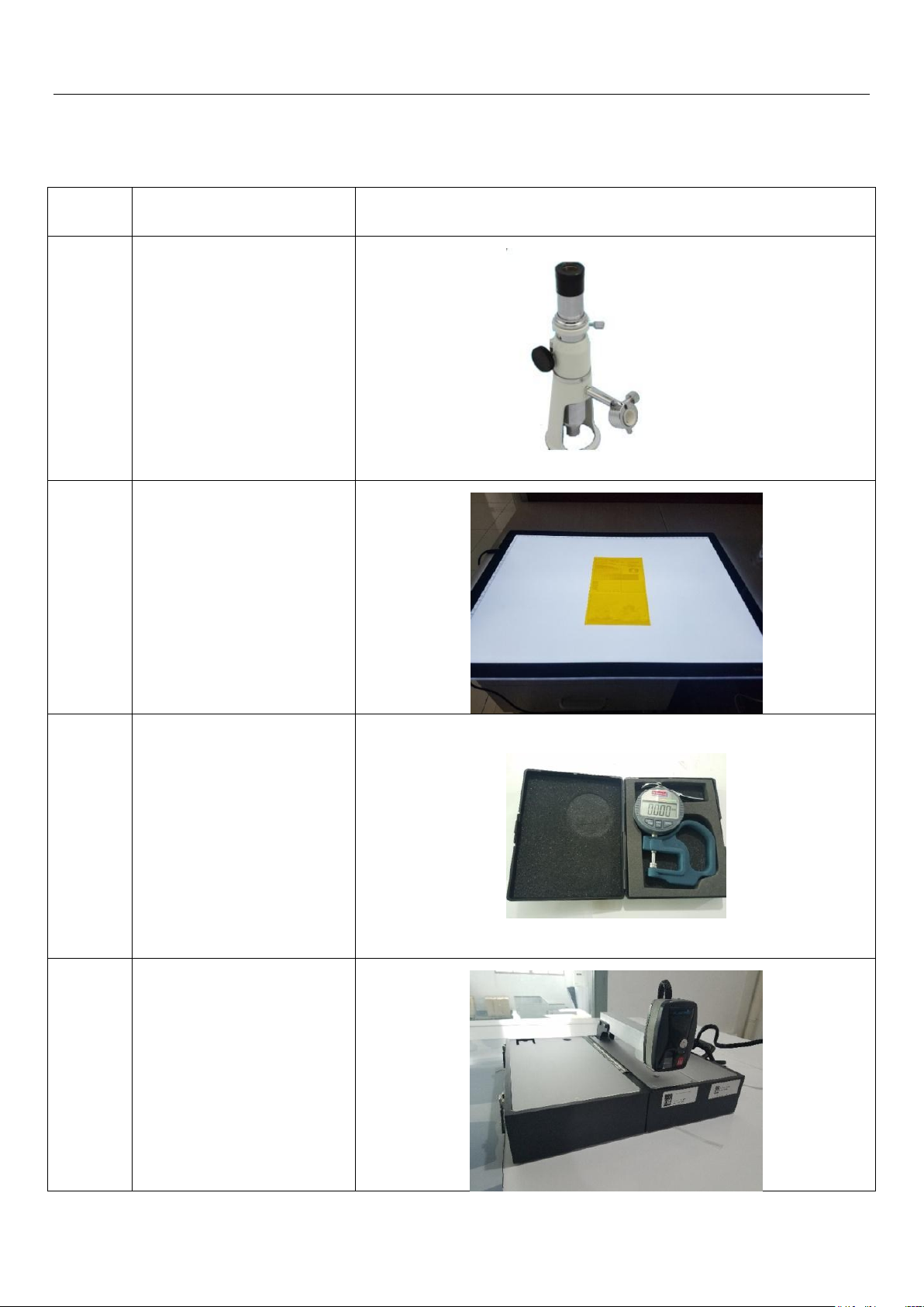
Consumables Parts and Spare Parts
No
Description
Figure
1
100X Optical Magnifier
2
LED back lighting viewing
board
3
Thickness Gauge (0.001mm)
4
3D Dots Measuring Device
7.3 Common instruments used for plate testing process
Table 7.3: Tools used during plate testing process
45 / 55
Page 46
Consumables Parts and Spare Parts
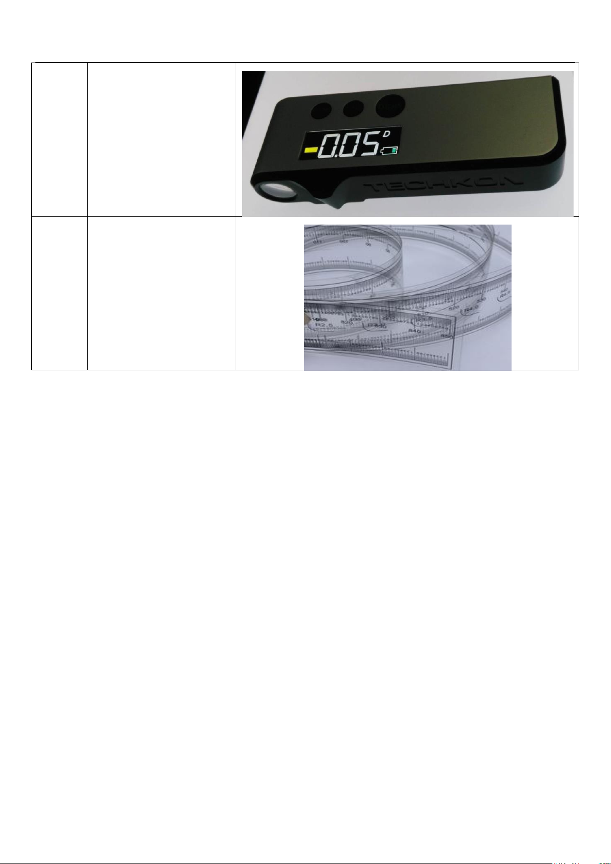
5
Transmission Densitometer
6
Film Ruler (1.5m)
46 / 55
Page 47
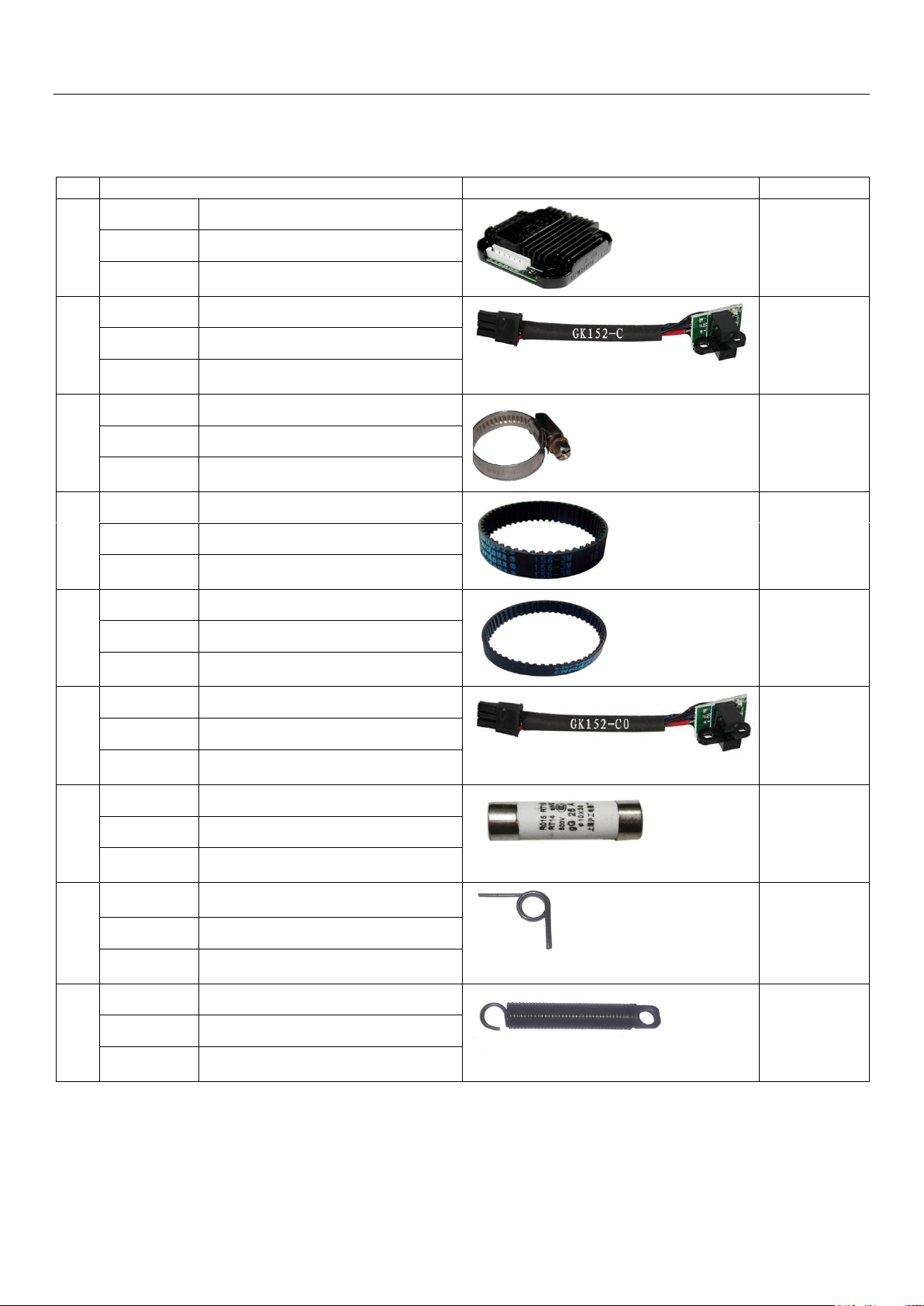
Consumables Parts and Spare Parts
No
DESCRIPTION
PICTURE
TYPE
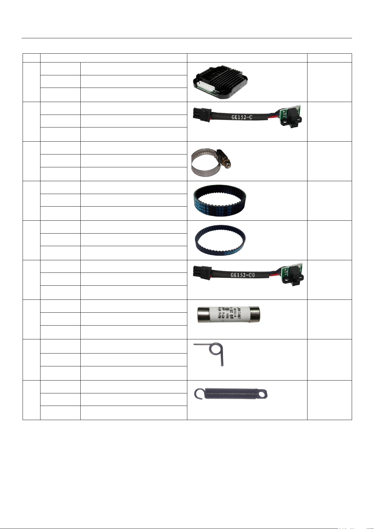
1
Parts Name
Driver UIM24004(2.9A)
Bundled with
new machine
Parts No
022021080
Details
Common driver for Drive Motors
2
Parts Name
Optocoupler Sensor
GK152-C/M
Bundled with
new machine
Parts No
022025063
Details
Used on mechanism drive motors for Zero
Positioning
3
Parts Name
Stainless Steel Hoop φ25-38
Bundled with
new machine
Parts No
050180030
Details
For pipeline connection fixation
4
Parts Name
Timing belt 156-3M-10
Bundled with
new machine
Parts No
022042347
Details
For stepping motor mechanism driving
5
Parts Name
Timing belt 42MXL025
Bundled with
new machine
Parts No
022042330
Details
For stepping motor mechanism driving
6
Parts Name
Optocoupler Sensor GK152-CO/M
Bundled with
new machine
Parts No
022028431
Details
Zero position sensor for scanning platform
(L/R)
7
Parts Name
(UL)
Fuse OTM10(250V/OA) /OTM20
Bundled with
new machine
Parts No
060108137/060108138
Details
For currents/pumps/laser box wiring
protections
8
Parts Name
H/Clamp Panel (R) Torsion Spring / (L)
Torsion Spring
Bundled with
new machine
Parts No
024412381/024412382
Details
H/clamp pressing pressure control for plate
head
9
Parts Name
T/Clamp pull spring
Bundled with
new machine
Parts No
024812700
Details
T/clamp pressing pressure control for plate
tail
Chapter 8: Consumables Parts and Spare Part
8.1 HDI-600Bundled Spare Parts List
Page 48
Consumables Parts and Spare Parts
No
DESCRIPTION
PICTURE
TYPE
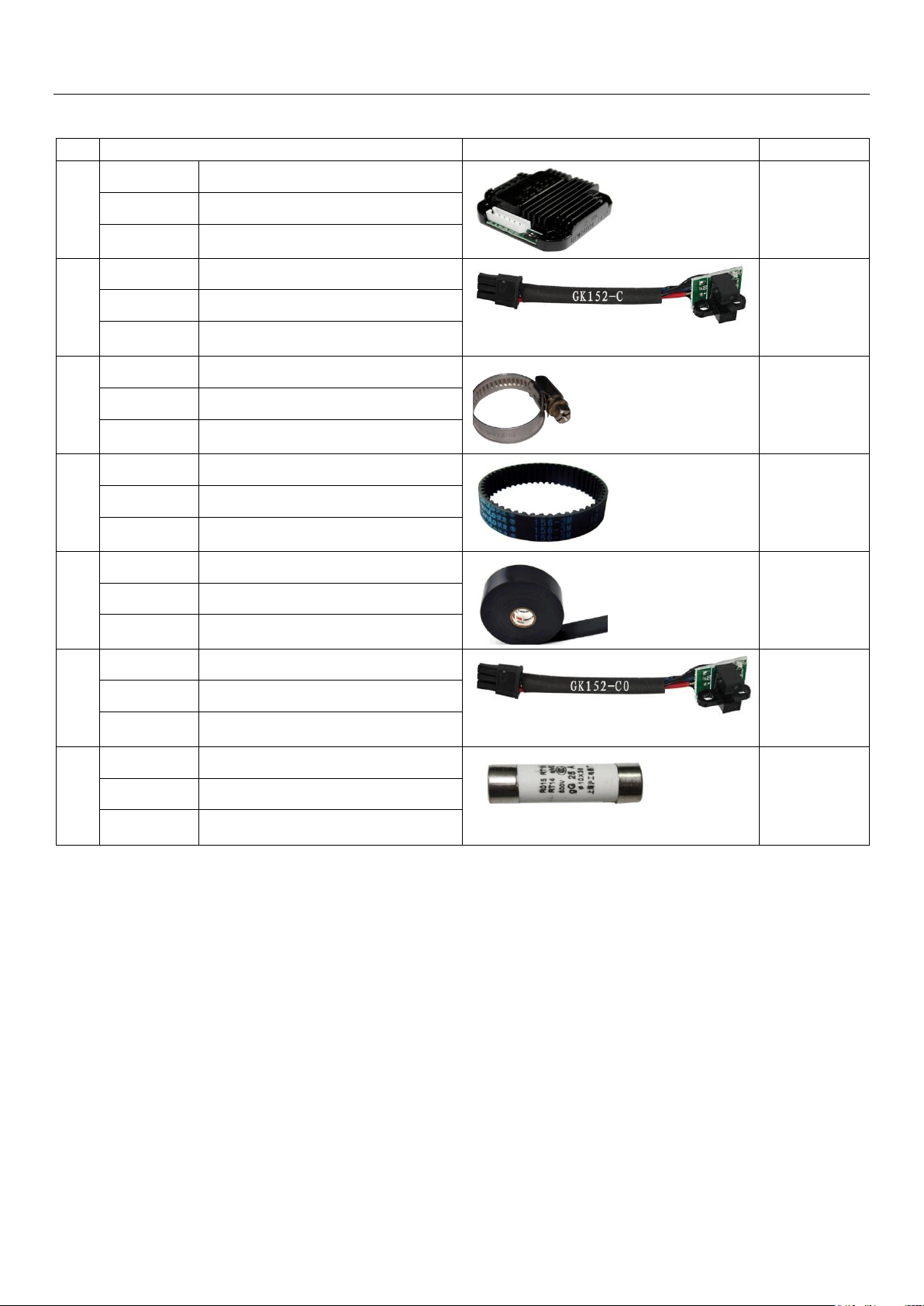
1
Parts Name
Driver UIM24004(2.9A)
Bundled with
new machine
Parts No
022021080
Details
Common driver for Drive Motors
2
Parts Name
Optocoupler Sensor
GK152-C/M
Bundled with
new machine
Parts No
022025063
Details
Used on mechanism drive motors for Zero
Positioning
3
Parts Name
Stainless Steel Hoop φ25-38
Bundled with
new machine
Parts No
050180030
Details
For pipeline connection fixation
4
Parts Name
Timing belt 156-3M-10
Bundled with
new machine
Parts No
022042347
Details
For stepping motor mechanism driving
5
Parts Name
Timing belt 42MXL025
Bundled with
new machine
Parts No
022042330
Details
For stepping motor mechanism driving
6
Parts Name
Optocoupler Sensor GK152-CO/M
Bundled with
new machine
Parts No
022028431
Details
Zero position sensor for scanning platform
(L/R)
7
Parts Name
(UL)
Fuse OTM10(250V/OA) /OTM20
Bundled with
new machine
Parts No
060108137/060108138
Details
For currents/pumps/laser box wiring
protections
8
Parts Name
H/Clamp Panel (R) Torsion Spring / (L)
Torsion Spring
Bundled with
new machine
Parts No
024412381/024412382
Details
H/clamp pressing pressure control for plate
head
9
Parts Name
Tail Clamp Pull Spring
Bundled with
new machine
Parts No
024812700
Details
T/clamp pressing pressure control for plate
tail
8.2HDI-920Bundled Spare Parts List
48 / 55
Page 49
Consumables Parts and Spare Parts
No
DESCRIPTION
PICTURE
TYPE
1
Parts Name
Driver UIM24004(2.9A)
Bundled with
new machine
Parts No
022021080
Details
Common driver for Drive Motors
2
Parts Name
OptocouplerSensor GK152-C/M
Bundled with
new machine
Parts No
022025063
Details
Used on mechanism drive motors for Zero
Positioning
3
Parts Name
Stainless Steel Hoop φ25-38
Bundled with
new machine
Parts No
050180030
Details
For pipeline connection fixation
4
Parts Name
Timing Belt 156-3M-10
Bundled with
new machine
Parts No
022042347
Details
For stepping motor mechanism driving
5
Parts Name
3M Electrical Tape
Bundled with
new machine
Parts No
060201754
Details
Plate end mounting used
6
Parts Name
OptocouplerSensorGK152-CO/M
Bundled with
new machine
Parts No
022028431
Details
Zero position sensor for scanning platform
(L/R)
7
Parts Name
茗熔保险管
RT18-32(R015)10A
Bundled with
new machine
Parts No
029083878
Details
To limit excessive current flows & prevent
wires from heating up and burns.
8.3 HDI-1600Bundled Spare Parts List
49 / 55
Page 50
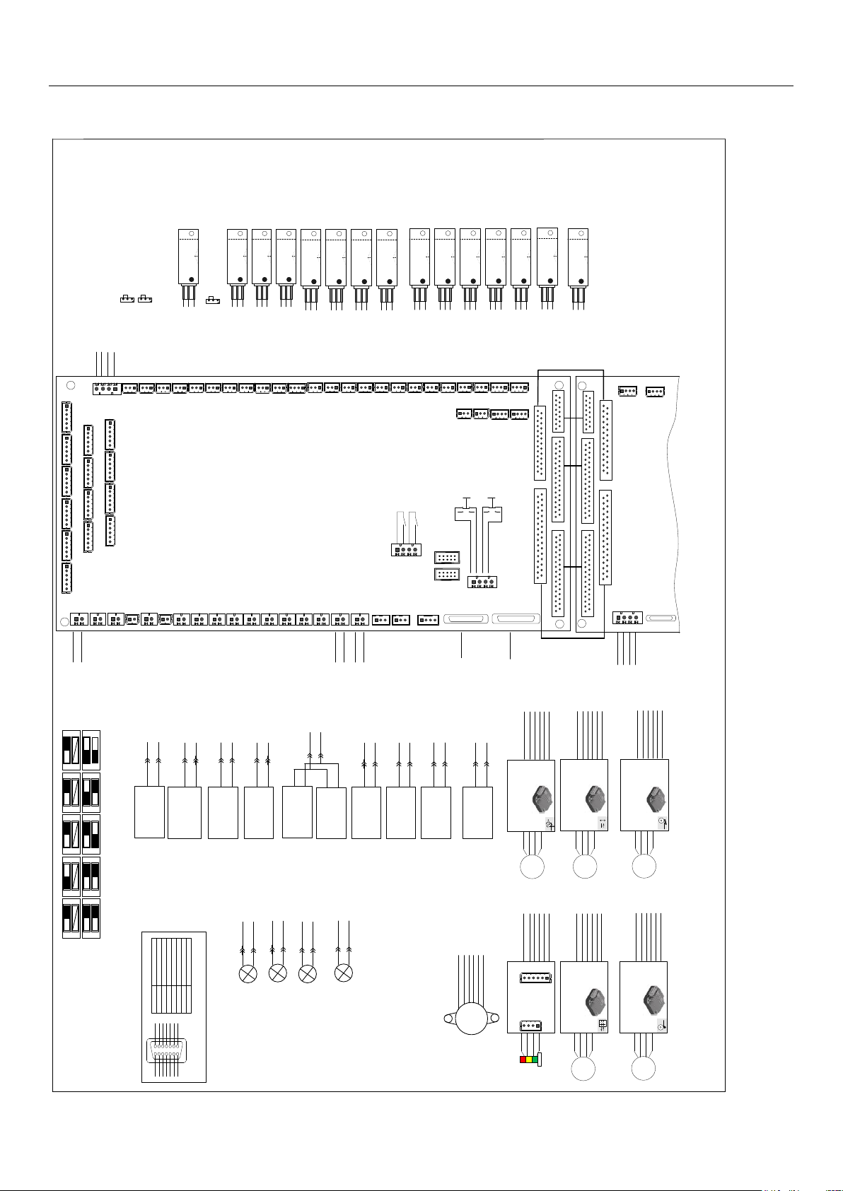
Chapter 9: Appendix -Wiring Diagram
M
2505M
装卸版动作电机
Plate pressing
motor
M
2506M
装版压版电机
Plate pressing
motor
M
2511M
焦距调节电机
Focus adjusting motor
2505D
UIM24004
8细分
Dial code 8
2511D
UIM24002
2细分
Dial code 2
2506D
UIM24004
8细分
Dial code 8
红
黑
143
5
棕黄绿
白
主板接口板
J11→
LBMIO-INT
J11→
2
6
红
黑
143
5
棕黄绿
白
主板接口板
J5→
LBMIO-INT
J5→
2
6
红
黑
143
5
棕黄绿
白
主板接口板
J6→
LBMIO-INT
J6→
2
6
RST
PUL
DIR
VCC
24-
24+
RST
PUL
DIR
VCC
24-
24+
RST
PUL
DIR
VCC
24-
24+
2.9A2.9A
1.0A
M
2512M
物距调节电机
Zoom adjust motor
2512D
UIM24002
2细分
Dial code 2
红
黑
143
5
棕黄绿
白
2
6
主板接口板
J12→
LBMIO-INT
J12→
RST
PUL
DIR
VCC
24-
24+
1.0A
M
2513M
翻版挡板电机
Plate loading&unloading action motor
2513D
UIM24002
8细分
Dial code 8
红
黑
143
5
棕黄绿
白
主板接口板
J13→
LBMIO-INT
J13→
2
6
RST
PUL
DIR
VCC
24-
24+
1.0A
红red
蓝blue
绿green
黑black
翻版挡板电机零位
Plate stopper motor
zero position
版尾↓方向按键
Tail clamp↓direction
button
焦距调节电机零位
Focus adjusting
motor zero position
装版压版电机零位
Plate pressing motor
zero position
装版光鼓表面检测
Loading Drum Check
气压急停信号
Vaccum emergency stop
detection
物距调节电机零位
Objective distance
adjusting zero position
取消发版键
Cancel button
3
1
2
-
+
IN
2109
→JS9
3
1
2
-
+
IN
2112
→JS12
312
-
+
IN
2113
→JS13
3
1
2
-
+
IN
2114
→JS14
312
-
+
IN
2115
→JS15
3
1
2
-
+
IN
2120
→JS20
3
1
2
-
+
IN
2121
→JS21
3
1
2
-
+
IN
2122
→JS22
装卸版动作电机零位
Plate loading&unloading
action motor zero position
3
1
2
-
+
IN
2103
→JS3
3
1
2
-
+
IN
2107
→JS7
3
1
2
-
+
IN
2108
→JS8
版尾↑方向按键
Tail clamp↑direction
button
确定按键
Confirm button
3
1
2
-
+
IN
2123
→JS23
3
1
2
-
+
IN
2124
→JS24
→JS1
→JS2
信号短接
Short-circuit
信号短接
Short-circuit
吸尘气压检测
Aspirating pressure
detection
3
1
2
-
+
IN
2126
→JS26
开盖停止信号
(安全开关)
Top cover safety switch
3
1
2
-
+
IN
2125
→JS25
版尾↓方向按键指示灯2603D
Tail clamp↓direction button
indicator light
确定按键指示灯2604D
Confirm button
indicator light
取消按键指示2607D
Cancel button
indicator light
CN4→
2
+ 1
-
24V
CN7→
2
+ 1
-
24V
CN3→
2
+ 1
-
24V
CN9B→
真空气泵变频器
Vacuum pump
inverter
2
1
2701D
CN4→
CN5→
平衡控制电磁铁(左)
Balance control
electromagnet(left)
2
1
2604D
2
1
2605D
版尾↑方向按键指示灯2602D
Tail clamp↑direction button
indicator light
CN2→
2
+ 1
-
24V
2514D
红
黑
143
5
棕黄绿
白
2
6
主板接口板
J14→
LBMIO-INT
J14→
RST
PUL
DIR
VCC
24-
24+
DR
ENPU
V+
+
V-
三色灯
控制板
Tri-color light
contorl panel
CN10→
光鼓表面检测零位
Loading Drum Check
zero position
2
1
2610D
CN12→
2
1
2612D
CN11→
压版锁定电磁铁
Pressure plate
locking
electromagnet
2
1
2611D
平衡控制电磁铁(右)
Balance control
electromagnet(right)
润滑油泵控制端口
Oil pump control
port
brown
yellow
green
White
Black
red
brown
yellow
green
White
Black
red
brown
yellow
green
White
Black
red
brown
yellow
green
White
Black
red
brown
yellow
green
White
Black
red
brown
yellow
green
White
Black
red
红red
棕brown
橙orange
黄yellow
红red
棕brown
橙orange
黄yellow
黄yellow
红red
橙orange
黑black
黄yellow
红red
橙orange
黑black
黑black
绿green
黄yellow
红red
三色灯
Tri-color light
HDI-600主控部分接线示意图
HDI-600 Mainframe Control Wiring Diagram
光鼓平衡位置检测
Drum balance
position detection
光鼓版尾位置检测
Tail clamp postion
detection
开盖停止信号(预留)
(安全开关)
Top cover safety switch
驱动器正面拨码
Driver front side dip
switch
驱动器背面拨码
Driver back side dip
switch
1
2ON1
2
ON
1
2ON1
2
ON
1
2ON1
2
ON
1
2ON1
2
ON
1
2ON1
2
ON
整步
Full step
2细分
Dial code 2
4细分
Dial code 4
8细分
Dial code 4
16细分
Dial code 16
B
 ̄Z ̄A ̄
GND
+5V
B
Z
A
8
9
10
11
12
13
14
6745231
BLUE 蓝
BLUE/BLACK 蓝/黑
GREEN 绿
GREEN/BLACK 绿/黑
YELLOW 黄
YELLOW/BLACK 黄/黑
RED 红
BLACK 黑
A CH Output
A CH Output
B CH Output
B CH Output
Z CH Output
Z CH Output
DC +5V
GND
 ̄
 ̄
 ̄
SCSI 14焊接式公头
Welded connector
HDI600-码盘2301S接线
HDI600-Encoder 2301S cable
→JS4
信号短接
Short-circuit
CN1→
版台靠规电磁铁
loading table side
gauge electromagnet
2
1
2601D
LBMIO-INT
主控制板接口
Main IO Board
1
226
25
JPC
JPB
JPA
KLUsb128
JPD
1
2
3
2
31
1
2
2
6
25
JPC
JPB
JPA
JPD
1
2
3
2
31
JPA
JPB
CNP5
+ V3 -
24V
+
-
COM1
连接激光控制模块
To laser control module
COM2
CNS1
CNS2
J33
CNP1
V1+
V1-
+
-
+
-
5V
CNP2
+
V2 -
24V
+
-
CN1
+
-
CN2
+
-
CN3
+
-
CN4
+
-
CN5
+
-
CN6
+
-
CN7
+
-
CN8
+
-
CN9
+
-
+
-
LH
+
-
RH
P5V
CN17
DSVEMT2
V3-
2204
平台左零位(B)
Left zero position
2203
平台右零位(A)
Right zero position
1
2
3
2
31
1
2
3
2
31
1
232
31
1
232
31
J35
J36
DSVEMT1
V3-
DSVEMT22
V3-
DSVEMT21
V3-
5V
GND
Input
5V
GND
光鼓(Y轴)伺服电机
驱动器
To Drum Servomotor
driver
直线(X轴)伺服电机
驱动器
To linear
Servomotor driver
CN1~CN14驱动输出,驱动电压为24V
CN1~CN14 Voltage output is 24V
主控制板
CN14
码盘2301S
Encoder2301s
JPE
GND
GND
RX
TX
紧停开关A
Emergency switch A
紧停开关B
Emergency switch B
2401S
CNP4 CN10
+
-
CN11
+
-
CN12
+
-
CN9B
CN10B
JS2JS3JS4JS5JS6JS7JS8JS9
JS10
JS12
V1-
V1+
DR
ENPU
V+
+
V-
+
IN
JS1
+
- IN
+
- IN
+
- IN
+
- IN
+
- IN
+
- IN
+
- IN
+
- IN
+
- IN
JS13JS14JS15JS16JS17JS28JS19JS20
+
- IN
+
- IN
+
- IN
+
- IN
+
- IN
+
- IN
+
- IN
+
- IN
+
- IN
JS22JS24
+
- IN
+
- IN
JS21JS23
+
- IN
+
- IN
JS11
-
5V
24V
IN
JS26
-
5V
24V
IN
JS28
-
5V
24V
IN
JS25
-
5V
24V
IN
JS27
-
5V
24V
IN
+
-
24V
GND
GND
RX
TX
平台右限位(A)
Right limitation
平台左限位(B)
Left limitation
安全开关2402S
磁簧开关2402S
J1J2
J3
J4
J5
J6
J7
J8
J9
J10
J11
J12
J13
J14
DR
ENPU
V+
+
V-
DR
ENPU
V+
+
V-
DR
ENPU
V+
+
V-
DR
ENPU
V+
+
V-
DR
ENPU
V+
+
V-
3红 red
2蓝 blue
1黑 black
3红 red
2蓝 blue
1黑 black
3红 red
2蓝 blue
1黑 black
3红 red
2蓝 blue
1黑 black
3红 red
2蓝 blue
1黑 black
3红 red
2蓝 blue
1黑 black
3红 red
2蓝 blue
1黑 black3*2蓝 blue
1黑 black
4红 red3*2蓝 blue
1黑 black
3红 red
2蓝 blue
1黑 black
3红 red
2蓝 blue
1黑 black1*2白 white3*3红 red
2蓝 blue
1黑 black3*2蓝 blue
1黑 black
3红 red
2蓝 blue
1黑 black
3红 red
2蓝 blue
1黑 black
3红 red
2蓝 blue
1黑 black
3红 red
2蓝 blue
1黑 black
3红2蓝1屏蔽
4红 red3*2蓝 blue
1黑 black
4红 red3*2橙 orange
1蓝 blue
DR
ENPU
V+
+
V-
DR
ENPU
V+
+
V-
DR
ENPU
V+
+
V-
DR
ENPU
V+
+
V-
DR
ENPU
V+
+
V-
DR
ENPU
V+
+
V-
DR
ENPU
V+
+
V-
DR
ENPU
+
V-
V+
2黑 black
1蓝 blue
2黑 black
1蓝 blue
2黑 black
1蓝 blue
2黑 black
1蓝 blue
2黑 black
1蓝 blue
2黑 black
1蓝 blue
2黑 black
1蓝 blue
2黑 black
1蓝 blue
2黑 black
1蓝 blue
2黑 black
1蓝 blue
2黑 black
1蓝 blue
2黑 black
1蓝 blue
蓝 blue
黑 black
蓝 blue
黑 black
蓝 blue
黑 black
蓝 blue
黑 black
蓝 blue
黑 black
蓝 blue
黑 black
蓝 blue
黑 black
蓝 blue
黑 black
蓝 blue
黑 black
蓝 blue
黑 black
蓝 blue
黑 black
蜂鸣器
BUZZER
BZ
2510D
主板接口板
J10→
LBMIO-INT
J10→
14352
6
黑 black
蓝 blue
CN8→
吸尘气泵变频器
Vacuum pump
inverter
2
1
2703D
除尘吹气电机
dust blowing motor
2
1
2703D
2
1
蓝 blue
黑 black
CN6→
2
1
2606D
光鼓有无版零位控制
Plate detection
sensor zero position
control
蓝 blue
黑 black
Appendix
Page 51
Appendix
T
B
-
C
P
L N
-24
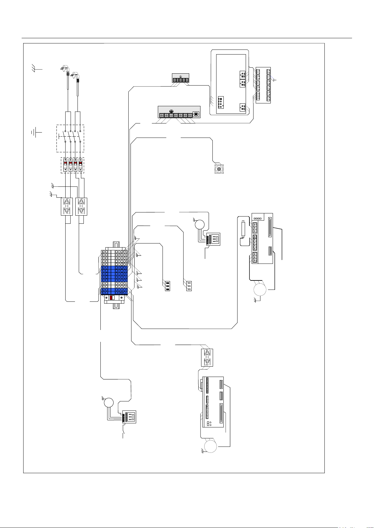
HDI-600供电部分接线示意图
HDI-600 Power Supply Part Wiring Diagram
2*14
#
AW
G
2*14#AWG
L N
-5
+5
SP-M
上海衡孚开关电源
HENGFU Switch Power
Supply
HF25W-SL-5
上海衡孚开关电源
HENGFU Switch Power Supply
HF320W-SC-24
保险丝座
Fuse Holder
TFBR-321N
SP-T
SP-M1
FLS
滤波器 filter
直线电机驱动器
linear Motor Driver
1
M
直线伺服电机
Linear Servomotor
SBSD-E
SBSD-C
3*16#AWG
2
*
16
#
AWG
DL-6D1
2701F
接线端子
Binding Post
3*16#AWG
3
*
16
#
AWG
真空气泵风机
Vacuum Pump Centrifuge Fan
卡固轴流风扇
KAKU Axial
flow Fan
KA1725/5HA2
BMT
M
2701P
漩涡真空气泵
Vacuum pump
2701D
主板接口板CN9B
LBMIO-CN9B
3*16#AWG
连接至激光控制箱
To laser control box
2701M
2*20#AWG
3
*
16
#
AWG
Laser
87
65
43
2
1
10A
T
B
-
M
P
-24
+24
+24
变频器(1.5kw)
inverter(1.5kw)
光鼓伺服驱动器(1.5kw)
Drum Servomotor driver
1
500W15Ω
制动电阻
Break Resistor
DSD-M
DSD-E
M
光鼓伺服电机1.5kW
Drum Servomotor 1.5kW
DSD-C
M
2703P
吸尘气泵
2BH220-H26
Aspirating vacuum pump
2703D
主板接口板CN8
LBMIO-CN8
3*16#AWG
2703M
87
65
43
2
1
变频器(1.5kw)
inverter(1.5kw)
N
FLM
FLC
主控电源输入
Control Power
Input(UPS)
220V 50Hz
主机电源输入
Mainframe
Power Input
220V 50Hz
N1
L1
L
滤波器 filter
滤波器 filter
N1
L1
L
N
N1
L1
N
L
N
N1
L1
L
FU20A
主板接口板CNS1
LBMIO-CNS1
DSD-P
主板接口板CNS2
LBMIO-CNS2
连接至制冷控制箱
To Refrigeration system
接地线
Ground
接对应设备壳体
For Related
Device Shield
主板接口板
Main I/O Board
(LBMIO-INT)
CNP1
CNP4 CNP5CNP2
CNP1 CNP2 CNP3 CNP4 CNP5
CNP6 CNP7 CNP8 CNP9CNP10CNP11
POWER-SH
黑 black
蓝 blue
黑 black
蓝 blue
黑 black
蓝 blue
黑 black
蓝 blue
黑 black
黑 black
蓝 blue
蓝 blue
黄 yellow
红 red
蓝 blue
蓝 blue
黑 black
黄 yellow
红 red
蓝 blue
蓝 blue
蓝 blue
黑 black
黑 black
蓝 blue
黄 yellow
红red
蓝 blue
黄 yellow
红red
轴流风机
Axial flow fan
DC24V
红 red
黄 yellow
蓝 blue
红 red
蓝 blue
L L L L L N N N N N L L N N
51 / 55
Page 52
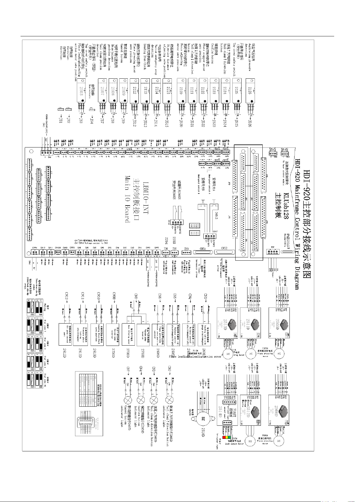
Appendix
52 / 55
Page 53
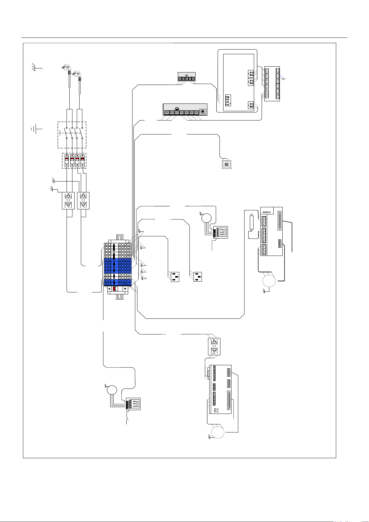
Appendix
T
B
-
C
P
L N
-24
HDI-920供电部分接线示意图
HDI-920 Power Supply Part Wiring Diagram
2*14 #AW
G
2*14 #AWG
L N
-5
+5
SP-M
上海衡孚开关电源
HENGFU Switch Power
Supply
HF 25 W-SL -5
上海衡孚开关电源
HENGFU Switch Power Supply
HF 320 W-SC -24
保险丝座
Fuse Holder
TFBR-321N
SP-T
SP-M1
FLS
滤波器 filter
直线电机驱动器
linear Motor Driver
1
M
直线伺服电机
Linear Servomotor
SBSD-E
SBSD-C
3*16#AWG
2*1
6
#AW
G
DL-6D1
2701F
接线端子
Binding Post
3*16 #AWG
3*1
6#A
W
G
真空气泵风机
Vacuum Pump Centrifuge Fan
轴流风扇
Axial flow Fan
KA1725/5HA2 BMT
M
2701P
漩涡真空气泵
Vacuum pump
2701D
主板接口板CN9B
LBMIO-CN9B
3*16#AWG
连接至激光控制箱
To laser control box
2701M
2*20 #AWG
3
*
16#
A
W
G
Laser
8765432
1
10A
T
B
-
M
P
-24
+24
+24
变频器(1.5kw)
inverter(1.5kw)
光鼓伺服驱动器(1.5kw)
Drum Servomotor driver
1
500W10Ω
制动电阻
Break Resistor
DSD-M
DSD-E
M
光鼓伺服电机1.5kW
Drum Servomotor 1.5kW
DSD-C
M
2703P
吸尘气泵
2BH220-H26
Aspirating vacuum pump
2703D
主板接口板CN8
LBMIO-CN8
3*16#AWG
2703M
87654321
变频器(1.5kw)
inverter(1.5kw)
N
FLM
FLC
主控电源输入
Control Power
Input(UPS)
220V 50Hz
主机电源输入
Mainframe
Power Input
220V 50Hz
N1
L1
L
滤波器 filter
滤波器 filter
N1
L1
L
N
N1
L1
N
L
N
N1
L1
L
FU20A
主板接口板CNS1
LBMIO-CNS1
DSD-P
主板接口板CNS2
LBMIO-CNS2
连接至制冷控制箱
To Refrigeration system
接地线
Ground
接对应设备壳体
For Related
Device Shield
黄 yellow
红 red
蓝 blue
蓝 blue
黑 black
黄 yellow
红 red
蓝 blue
蓝 blue
蓝 blue
黑 black
黑 black
主板接口板
Main I/O Board
(LBMIO-INT)
CNP1
CNP4 CNP5CNP2
CNP1 CNP2 CNP3 CNP4 CNP5
CNP6 CNP7 CNP8 CNP9CNP10CNP11
POWER-SH
黑 black
蓝 blue
黑 black
蓝 blue
黑 black
蓝 blue
黑 black
蓝 blue
黑 black
黑 black
蓝 blue
蓝 blue
L L L L L N N N N N L L N N
棕 broen
蓝 blue
红 red
黄 yellow
蓝 blue
红 red
蓝 blue
黄 yellow
蓝 blue
红 red
黄 yellow
蓝 blue
红 red
轴流风机
Axial flow fan
DC24V
红 red
黄 yellow
蓝 blue
53 / 55
Page 54
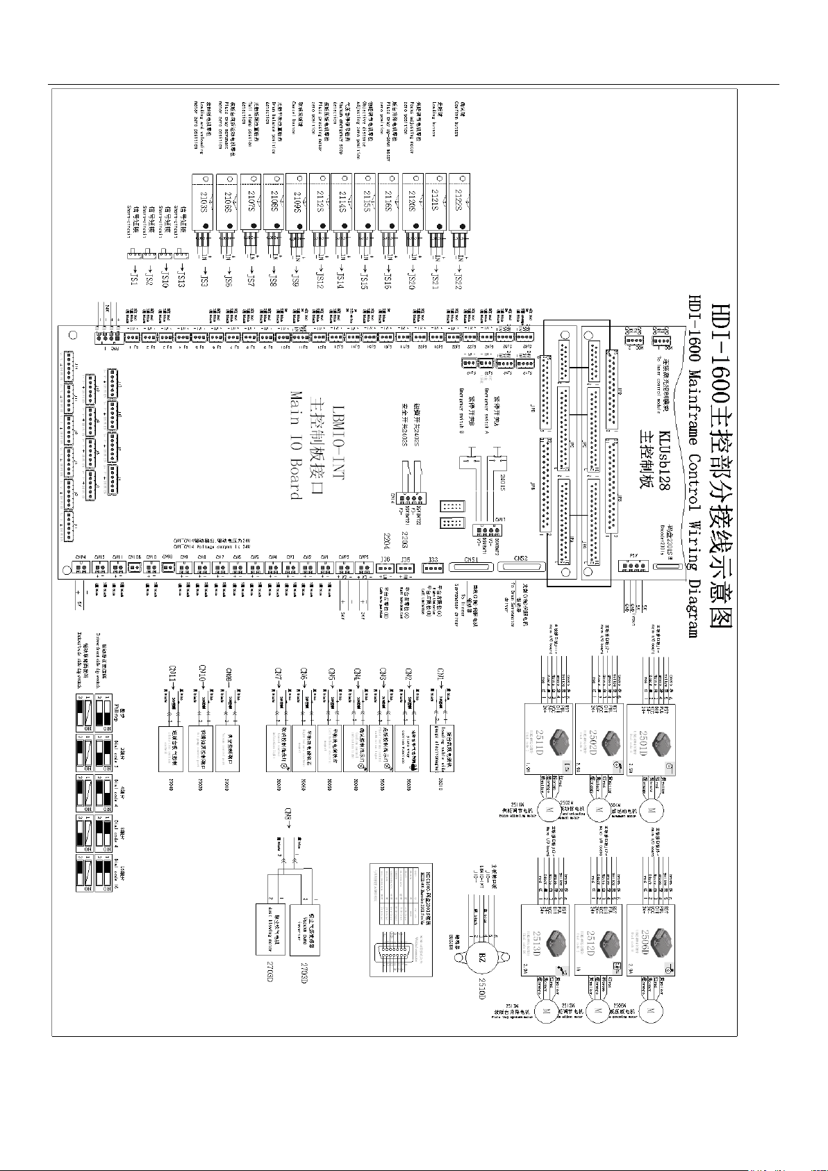
Appendix
54 / 55
Page 55
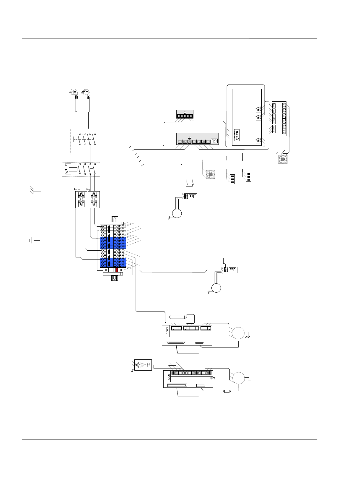
Appendix
TB-CP
10A
TB-MP
L1
L
N
N1
L1
L
N
N1
安全开关
Switch
L
N1
N
L1
L N
-24
L N
-5
+5
SP-M
上海衡孚开关电源
HENGFU Switch Power Supply
HF25W-SL-5
上海衡孚开关电源
HENGFU Switch Power Supply
HF320W-SC-24
SP-M1
-24
+24
+24
直线伺服电机驱动器
Linear servomotor Driver
1
SBSD-M
SBSD-E
M
SBSD-C
R S T
LC1 LC2
-
P(+)
U VT C W
3
*
16
#
AWG
连接至制冷控制箱
To Refrigeration system
真空气泵风机
Vacuum Pump
Centrifuge Fan
连接至激光控制箱
To laser control box
M
2701P
真空气泵
4BH320-H36
vacuum pump
主板接口板CN9B
LBMIO-CN9B
3*16#AWG
2701M
87
65
43
2
1
变频器
frequency converter
3
*
16
#
AWG
细分盒
Signal adapter
HDI-1600动力部分接线示意图
HDI-1600 power part wiring diagram
主机电源输入
Mainframe Power Input
220V 50Hz/60Hz 10A
FLM
滤波器 filter
滤波器 filter
FLC
滤波器 filter
M
3*16#AWG
2703M
87
65
43
2
1
吸尘/进版气泵
2BH220-H16
dust cleaner/loading
vacuum pump
主机电源输入
Mainframe Power Input
220V 50Hz/60Hz 16A
主板接口板CN11
LBMIO-CN11
主板接口板CN8
LBMIO-CN8
光鼓伺服驱动器
Drum Servomotor driver
1
400W10Ω
制动电阻
Break Resistor
DSD-M
DSD-E
M
光鼓伺服电机
Drum Servomotor
DSD-C
变频器
frequency converter
SP-T
Laser
SP-F
2703P
DSD-P
SBSD-P
直线伺服电机
Linear Servomotor
主板接口板CNS2
LBMIO-CNS2
主板接口板CNS1
LBMIO-CNS1
接地线
Ground
接对应设备壳体
For Related
Device Shield
速普接线端子
SUPU Binding Post
204951&204954
主板接口板
Main I/O Board
(LBMIO-INT)
CNP1
CNP4 CNP5CNP2
CNP1 CNP2 CNP3 CNP4 CNP5
CNP6 CNP7 CNP8 CNP9CNP10CNP11
黑 black
蓝 blue
黑 black
蓝 blue
黑 black
蓝 blue
黑 black
蓝 blue
黑 black
黑 black
蓝 blue
蓝 blue
黄 yellow
红 red
蓝 blue
蓝 blue
黑 black
黄 yellow
红 red
蓝 blue
蓝 blue
蓝 blue
黑 black
黑 black
红 red
黄 yellow
蓝 blue
红 red
黄 yellow
蓝 blue
蓝 blue
红 red
55 / 55
 Loading...