

Page 1
Emotron M20
Shaft Power Monitor
Instruction manual
English
Page 2

Contents
1 Inside the Box............................................................................. 3
2 Safety .......................................................................................... 4
3 Description.................................................................................. 5
4 Getting Started ........................................................................... 7
4.1 Please note ................................................................................................. 7
4.2 Connection and set-up before first start ................................................... 7
4.3 First start ..................................................................................................... 8
4.4 Manual setting of alarm levels, alternative A ........................................... 9
4.5 Manual setting of alarm levels, alternative B ........................................ 10
4.6 Manual setting of alarm levels, alternative C ........................................ 10
5 Wiring ........................................................................................ 11
5.1 Alternative example for single-phase connection ................................. 13
5.2 Example - digital input ............................................................................. 14
6 Selection of Current Transformer ........................................... 14
6.1 Motors less than 100 A........................................................................... 14
6.2 Motors greater than 100 A ..................................................................... 17
7 Operation .................................................................................. 19
7.1 Overview ................................................................................................... 19
7.2 Window menu .......................................................................................... 20
7.3 How to change a value ............................................................................ 21
8 Programming ............................................................................ 22
8.1 Set measurement unit, kW or HP ........................................................... 22
8.2 Setting rated motor power and current (window 41 and 42) ............... 24
8.3 Setting number of phases (window 43) ................................................. 25
8.4 Monitor function (window 05)................................................................. 25
8.5 Setting the Start Delay (window 31)....................................................... 27
Emotron AB 01-2151-01r4 1
Page 3

8.6 Setting alarm levels with Auto set ........................................................... 28
8.7 Setting the Response Delay (windows 32 and 34)................................ 29
9 Advanced Features .................................................................. 31
9.1 Setting alarm levels manually (windows 11-14) .................................... 31
10 Troubleshooting ....................................................................... 41
11 Technical Data ......................................................................... 43
12 Parameter List.......................................................................... 47
13 Service ...................................................................................... 50
2 Emotron AB 01-2151-01r4
Page 4
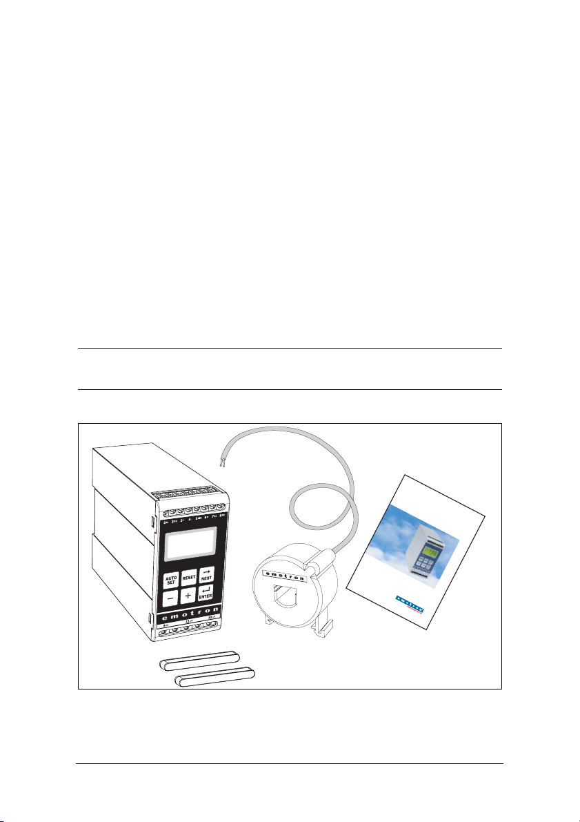
1 Inside the Box
Please check the delivery. Despite the fact that all products from Emotron are
carefully inspected and packed, transport damage may occur:
• Your shipment should contain the Emotron M20 shaft power monitor,
a current transformer, 2x terminal covers (option*) and this instruction
manual.
• Check carefully that the equipment ordered complies with the motor’s input
voltage and that the current transformer rating is as stated on the delivery
packaging.
• Check that the contents have not been damaged during shipping.
• If something is missing, or has been damaged, contact the supplier as well as
the forwarding agent within 48 hours of receipt.
NOTE: If in doubt contact your supplier before installing or commissioning
the product.
Shaft P
Emotron M20
ower Monitor
M20
In
s
tr
u
c
t
io
n
m
a
n
u
E
a
n
l
glish
*)
Emotron AB 01-2551-01r4 Inside the Box 3
Page 5

2Safety
• Study this manual thoroughly before installing and using the monitor.
• The monitor must be installed by qualified personnel.
• Always disconnect supply circuits prior to installing.
• The installation must comply with standard and local regulations.
• Pay special attention to the information in this chapter and the parts marked
CAUTION in the Operation and Programming chapters.
• Check that the monitor and the equipment are correctly connected before it
is taken into use.
• Should questions or uncertainties arise, please contact your local sales outlet
or see chapter 13, Service.
• Faults that arise due to faulty installation or operation are not covered by the
warranty.
NOTE: Removing or tampering with the seal on the housing will invalidate
the warranty.
4Safety Emotron AB 01-2551-01r4
Page 6

3 Description
This instruction manual describes the installation and commissioning of the
Emotron M20 shaft power monitor. The Emotron M20 supervises induction
motor driven equipment and provides warnings when abnormal conditions are
detected. It protects for example, pumps and other equipment. The M20’s ability to provide reliable monitoring and protection ensures that production equipment is optimized and expensive breakdowns and interruptions are minimized.
The Emotron M20 uses the motor as its own sensor and no external sensors or
extra cabling are required. Due to the special method of subtracting motor
power losses, the monitor is able to accurately measure the shaft power supplied
by the motor to the application. This advanced technique allows the M20 to
monitor only the “application” load rather than the “total” motor load, which
includes the varying motor losses.
The shaft power is calculated by measuring motor input power, and subtracting
the motor power loss calculated using a unique principle. The shaft power output is indicated on the monitor display in kW or HP, or as a percentage of rated
power. Calculating shaft power gives more reliable supervision than non-linear
techniques, such as current and phase angle measurements. Current measurement is only sufficient at high motor loads and phase angle only at low loads.
Input power is sometimes called true or real power. Input power is linear, but
ignores motor power loss.
The M20’s analogue output and two relay outputs allow the combination of
direct and indirect control. The unit offers high accuracy in the event of very
small load variations. The analogue output signal can be used to scale the
machine load to represent the actual working range.
The monitor is very easy to install and set up and should be mounted on a
standard DIN rail. It is also very easy to use. The “Auto set” function makes it
possible to adjust the monitor automatically by pressing just one key.
The M20 provides complete flexibility in terms of the type of protection
required for your application. You may select either overload and underload
protection or simply overload with pre-alarm or underload with pre-alarm.
Independent response delays can be selected for both overload and underload
protection. Additional flexibility is provided in the form of programmable output relays, number of start attempts, number of reversing attempts etc.
Emotron AB 01-2551-01r4 Description 5
Page 7

The Emotron M20 shaft power monitor offers advanced multi-function monitoring and a display for load indication and parameter setting. It is ideal for
protecting many different applications including pumps in general, centrifugal
pumps, magnetic pumps, screw and impeller pumps, mixers, scrapers, crushers,
conveyor systems, etc.
For further information, please see www.emotron.com.
6Description Emotron AB 01-2551-01r4
Page 8

4 Getting Started
NEXT
ENTER
NEXT
4.1 Please note
1. Pay special attention to the safety section in this manual and parts marked
CAUTION.
2. Check that motor/supply voltage corresponds to values on the monitor
product label at the side of the unit.
3. Make a note of the motor’s rated power and full load amps from its nameplate. Confirm that the current transformer supplied is of the correct size
according to tables 1 and 2 in chapter 6 of this manual.
4.2 Connection and set-up before first start
1. Connect the Emotron M20 according to chapter 5 and Fig. 1.
2. Make sure all safety measures have been taken and switch on the supply
voltage.
3. Use the key to scroll through the menu. Press and hold the key and
ENTER
press the key to scroll back.
4. Set rated motor power and current in windows 41 and 42. Additional settings to be programmed are discussed in chapter 8.
5. Set monitor function in window 05, overload and underload or only underload or only overload. See chapter 12, Parameter list, for range and default
values.
6. Set start delay and response delay in window 31 and 32/34.
7. Compare all set values with the parameter list in chapter 12 to confirm that
all relevant values are set. Advanced features will be found in chapter 9.
Emotron AB 01-2551-01r4 Getting Started 7
Page 9

4.3 First start
SET
AUTO
CAUTION: Make sure that all safety measures have been taken before
switching on the supply voltage and starting the motor/machine in order to
avoid personal injury.
1. Start the motor/machine and let it run at normal load, until the Start Delay
has expired.
AUTO
2. Press for 3 seconds.
Hint!
Short-circuit the output relays during the set-up; this prevents the equipment
from stopping unintentionally.
More Hints!
The monitor can be set in three different ways:
1. Automatically by pressing the Auto set key as described above. The Auto set
2. If Auto set is used as above, the margins can be re-adjusted manually (win-
SET
function performs a measurement (momentarily) of the actual load and sets
relevant alarm levels for this actual load plus/minus the “margins” (Default;
Max +16% and Min -16%).
dows 21-24). When the margin values are changed a new Auto set must
always be performed to activate the changes and the new margins. More
information is provided in chapter 9, Advanced Features.
3. Manual setting of alarm levels (windows 11-14). The alarm levels can be set
manually, without using the Auto set. See sections Manual setting of alarm
levels, alternative A, B and C.
NOTE: If any window parameter is manually adjusted, the display will flash
the new value to indicate that a change has been made. The Enter key must
be pressed for the M20 to accept this new value.
8 Getting Started Emotron AB 01-2551-01r4
Page 10

4.4 Manual setting of alarm levels,
alternative A
Running and setting at normal load
• Start the motor/machine or pump and let it run at normal load, until the
Start Delay (window 31) has expired.
• Read off the load on the monitor display, e.g. 65%, window 01
(or kW/HP).
• Set the max. main alarm level to something between e.g. 70-85% in window
11. This must be set to the actual application requirements, maximum load
for machine/process.
• Set the min. main alarm level to something between e.g. 60-45% in window
14. This must also be set to the actual application requirements.
See also Fig. 7 in section 8.4, Over- and underload monitor.
Emotron AB 01-2551-01r4 Getting Started 9
Page 11

4.5 Manual setting of alarm levels,
alternative B
Running and setting at maximum load as well as at
minimum load
• Start the motor/machine or pump and let it run at maximum load, until the
Start Delay has expired. E.g. fill the conveyor with maximum allowed goods.
• Read off the load on the monitor display, e.g. 85% (window 01).
• Set the max. main alarm level to something between e.g. 90-95% in window
11. This must be set to the actual application requirements, maximum load
for both machine and processes.
• Then run the motor/machine and let it run at minimum load, e.g. idling,
until the Start Delay has expired.
• Read off the load on the monitor display, e.g. 30%.
• Set the min. main alarm level to something between e.g 25-20% in window
14. This must also be set to the actual application requirements.
See also Fig. 7 in section 8.4, Over- and underload monitor.
4.6 Manual setting of alarm levels,
alternative C
It is also possible to approximately calculate or estimate the alarm levels. If e.g.
the motor used is 22 kW, 22 must be set in window 41. This means that each
percentage point corresponds to 220 W (22 kW/100 = 220 W), and the alarm
limits in window 11- 14 can be set in steps of 220 W. If the max. alarm level is
set to 80% in this example, the monitor will emit an alarm and stop the
machine at approx. max. 17.6 kW shaft output power.
NOTE: If the pre-alarm is not used, the values for Min. pre-alarm and Max.
pre-alarm can be set to 0 (window 13) and 125% (window 12) respectively.
This will eliminate pre-alarm warning indications in the monitor display
when not in use.
See also Setting alarm levels manually in chapter 9, Advanced Features.
10 Getting Started Emotron AB 01-2551-01r4
Page 12

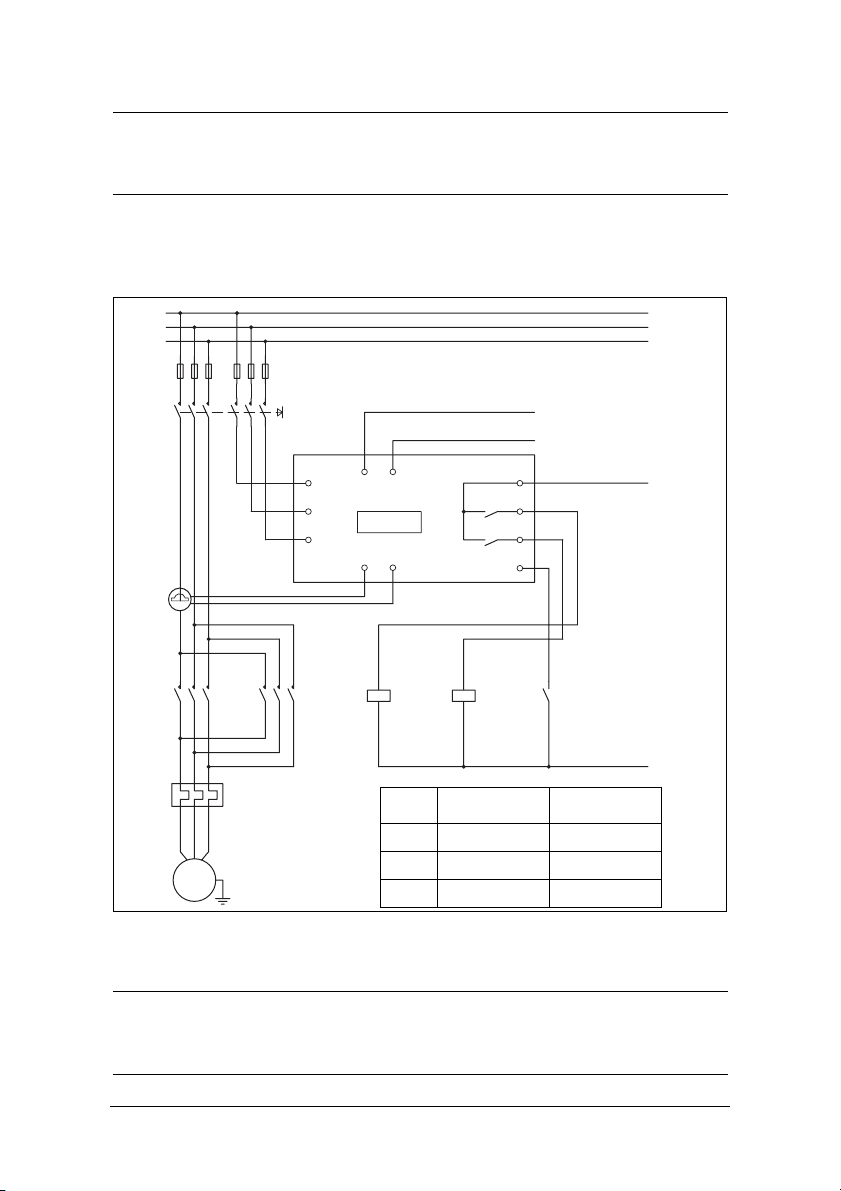
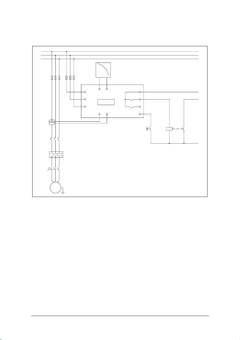
5 Wiring
The following wiring diagram provides an example of how the M20 can be connected to control the start/stop circuit of a three-phase motor, Fig. 1. Co nnections to a single-phase motor are described later in this manual (Fig. 2) as are the
programming changes necessary for such applications. The default setting for
the M20 is 3-phase.
1. The current transformer CTMxxx must be placed in the same phase that is
connected to terminal 9, phase L1, see Fig. 1. Failure to follow this requirement will result in the monitor failing to function.
2. For single-phase connection see fig 2.
When using DC voltage, terminal 6 should be connected to negative polarity
(ground) and terminal 5 to positive polarity (max. 48 VDC). See also Alternative auxiliary circuit (Fig. 16) in chapter 9.
Note: The current transformer (CTMxxx) must be placed in the same phase
that is connected to terminal 9, phase L1, see Fig. 1.
Emotron AB 01-2551-01r4 Wiring 11
Page 13

L1
L2
L3
NOTE: In power
down, both relays
are always N.O.
9
3
4
L1
A+ A-
11
L2
M20
13
L3
S2S1
1
2
6
C
7
R1
8
R2
5
DIG
Max. 240 VAC (alt. 0 VDC-)
CTMxxx
Please see CTM
K1
UVW
information
on Page 11.
NOTE: Monitor
voltage see
Note below.
-Reset
-Auto set
- Block
K1
{
PREALARM
Stop
Start
K1
N (alt. 48 VDC+)
M
Fig. 1 Connection example
NOTE: If the START/STOP is connected as per Fig. 1, it is recommended that
terminals 6 and 7 be bypassed during programming. After the programming
is completed the bypass must be taken out. Make sure that the monitor
voltage range e.g. 3x380-500 VAC matches the connected motor/line
voltage, e.g. 3x 400 V.
Please use the enclosed plastic (rubber) insert (if ordered, optional) to cover the
monitor terminals.
12 Wiring Emotron AB 01-2551-01r4
Page 14

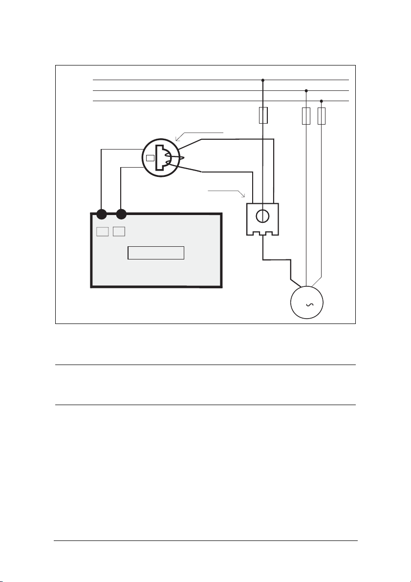
5.1 Alternative example for single-phase
connection
This wiring example shows the connections required for single-phase applications.
Refer to Fig. 1 for the remaining wiring.
L1
N
CTMxxx
K1
9
3
M20
S1 S2
1
4
C
A-A+
R1
R2
2
L1
11
L2
13
L3
NOTE: Monitor
DIG
6
7
8
5
voltage, see
note below.
L
N
M
Fig. 2 Single-phase connection example.
NOTE: In Fig. 2 make sure that the monitor voltage range e.g. 1x100-240 VAC
matches the connected motor/“line – neutral” voltage, e.g. 1x 230 V.
Emotron AB 01-2551-01r4 Wiring 13
Page 15

5.2 Example - digital input
The digital input uses terminals 5 (DIG) and 6 (C - reference). Either a VAC or
a VDC signal may be used. Connect + to terminal 5 (DIG) and - to terminal 6
for VDC signal. Please note the polarity when DC voltage is used. See also
Fig1
and terminal 6: Max. 240 VAC (or 0 VDC-) and on terminal 5: N
(or 48 VDC+).
VAC VDC
M20 M20
See also chapter 9, Advanced Features.
6
C
DIG
5
~
Max 240 VAC
~
DIG
6
C
5
-
Max 48 VDC
+
Note polarity!
Fig. 3 Wiring example for digital input.
6 Selection of Current Transformer
6.1 Motors less than 100 A
1. Check the rated motor current on the motor plate.
2. Compare this value with the current in Table 1.
3. From Table 1, select the current transformer and the appropriate number of
windings.
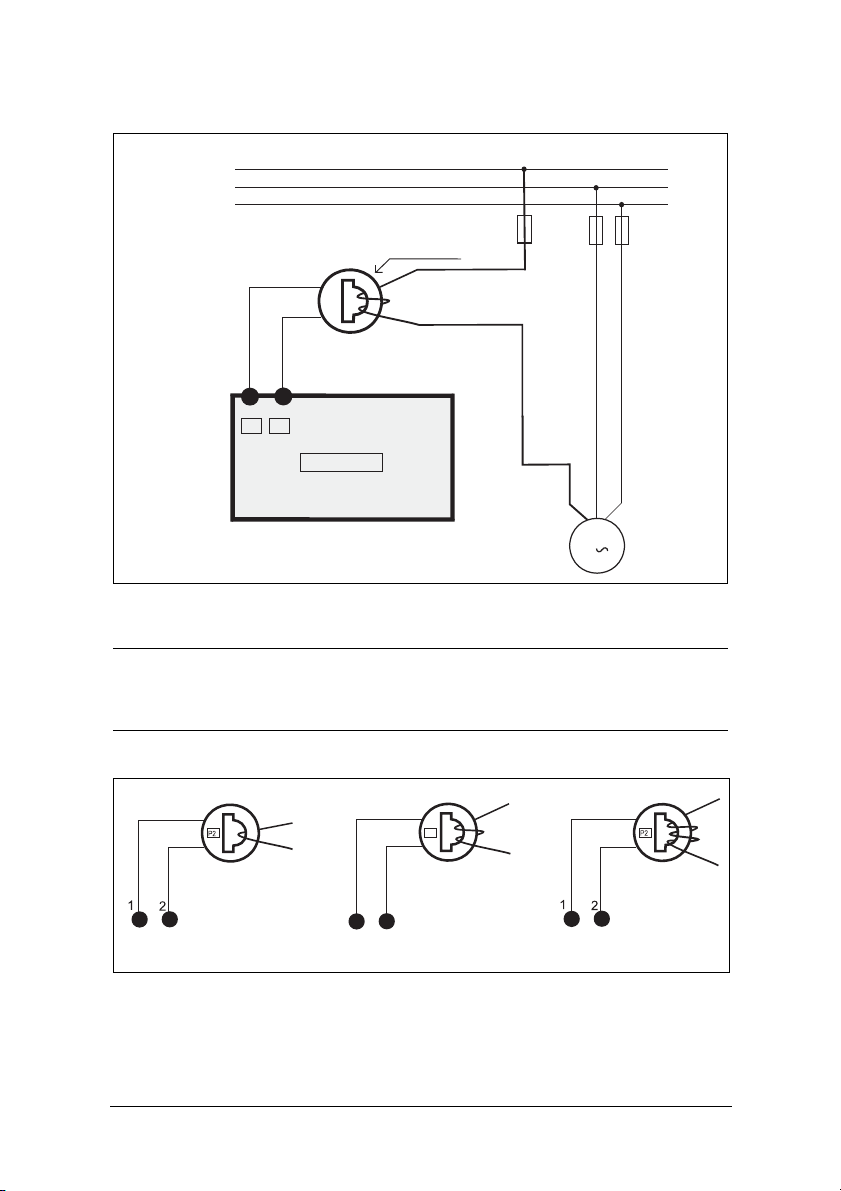
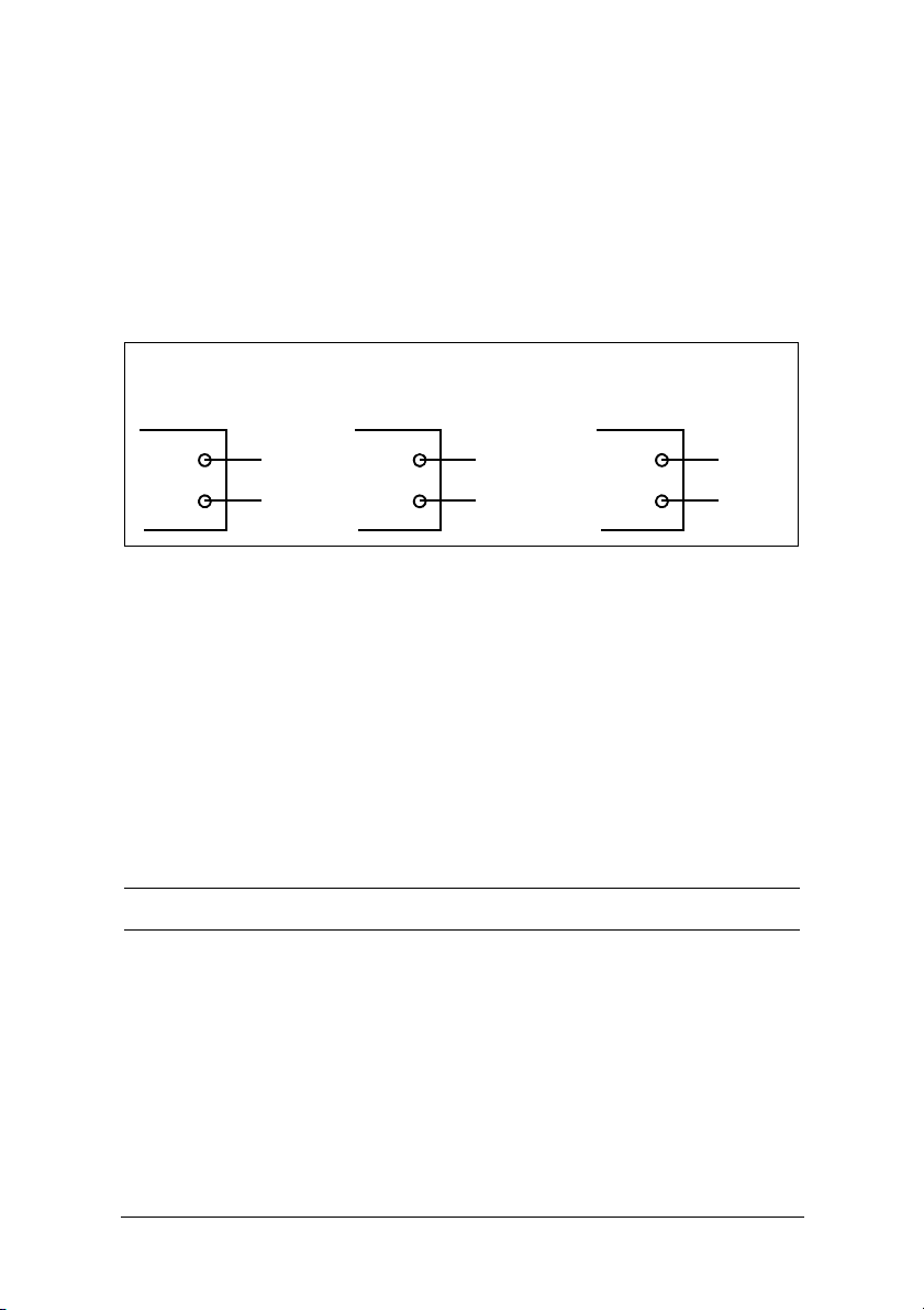
Fig. 5 shows the different types of current transformer (CT) windings. In Fig.
5:1 the motor wire is just drawn through the CT, in the text and tables below
this is described as 1 (one) winding. Fig. 5:2 shows a CT with 2 windings and
Fig. 5:3, 3 windings. In other words the number windings is equal to the
number of times the motor wire “L1” is drawn through the hole of the current
transformer.
NOTE: Maximum length of the CTM cable is 1 m (39 inches).
14 Selection of Current Transformer Emotron AB 01-2551-01r4
Page 16

Example
• Rated motor current = 12 A.
• Select 10.1-12.5 A from the first column in Table 1.
• This gives:
CTM025 with 2 windings (the motor wire is drawn through the CT’s hole
twice).
Table 1 Motors and CT less than 100 A
CURRENT TRANSFORMER TYPE and
RATED MOTOR
CURRENT [A]
CTM 010 CTM 025 CTM 050 CTM 100
0.4 – 1.0 10
1.01 – 2.0 5
2.01 – 3.0 3
3.1 – 5.0 2
5.1 – 10.0 1
10.1 – 12.5 2
12.6 –25 1
26 – 50 1
51 – 100 1
NUMBER OF WINDINGS
In order to ensure an accurate calibration of the M20, it is essential that you use
the correct CTM and apply the exact number of windings in accordance with
the above table.
NOTE: Normally the appropriate Current Transformer will have been ordered
and shipped with the M20. Check that this is the case; contact the supplier
if in doubt.
Emotron AB 01-2551-01r4 Selection of Current Transformer 15
Page 17
L1
L2
L3
CTM025
1
S1
P2
2
S2
M20
2 windings
M
3
Fig. 4 Example CTM 025 with 2 windings for a 12 A motor
NOTE: The current transformer connection and orientation are not polarity
sensitive, but must be connected to the same phase that is being
referenced for terminal 9 of the M20.
P2
1
2
5:1 5:2 5:3
Fig. 5 Example 1, 2 and 3 windings.
16 Selection of Current Transformer Emotron AB 01-2551-01r4
Page 18

6.2 Motors greater than 100 A
1. Check the rated motor current on the motor plate.
2. Compare this value with the current in Table 2.
3. Select the primary and secondary current transformer and the appropriate
number of windings from the columns in Table 2.
Please note that the ratio of the primary transformer must be exactly as provided
in the table below, otherwise the monitor power calculations will be inaccurate.
This will affect power readings, settings etc.
Example
• Rated motor current = 260 A.
• Select 251-500 A from the first column in Table 2.
• This gives:
- Primary transformer 500:5, 1 winding. (The motor wire is drawn through
the primary transformer once).
- CTM010 with 2 windings. (The wire from the primary transformer is
drawn through the hole in the CT, "CTM10", twice).
Table 2 CT greater than 100 A.
RATED MOTOR
CURRENT [A]
101 – 150
151 – 250
251 – 500
501 – 999
NOTE: Check that the appropriate Current Transformers has been ordered
and shipped with the M20. Contact the supplier if in doubt.
Emotron AB 01-2551-01r4 Selection of Current Transformer 17
CURRENT TRANSFORMER TYPE and
NUMBER OF PRIMARY WINDINGS
150:5 + CTM 010
1+ 2
250:5 + CTM 010
1+ 2
500:5 + CTM 010
1+2
1000:5 + CTM 010
1+ 2
Page 19
L1
L2
L3
CTM010
1
S1
P2
2
S2
2 windings
1 winding
S1 S2
500:5
M20
M
3
Fig. 6 Example of a CTM 010 with 2 windings and a primary transformer
500:5 with 1 winding for a 260 A motor.
NOTE: The transformer connection and orientation are not polarity sensitive, but must be connected to the same phase that is being referenced for
terminal 9 of the M20.
18 Selection of Current Transformer Emotron AB 01-2551-01r4
Page 20
7 Operation
2123
Make sure the enclosed plastic (rubber) insert (if ordered, optional) covers the
monitor terminals before you start programming.
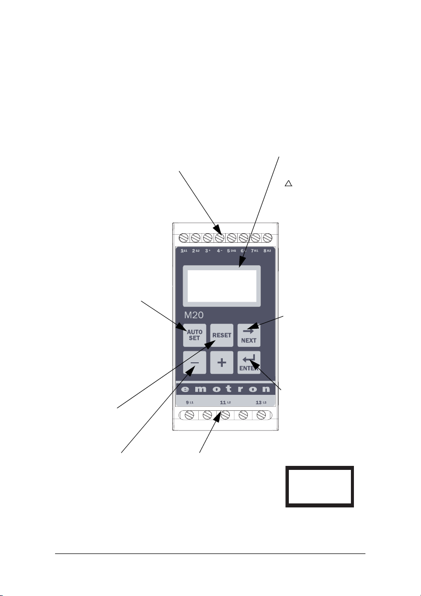
7.1 Overview
Control Terminals
1 S1 Current transformer input
2 S2 Current transformer input
3 + Analogue output
4 - Analogue output
5 DIG External RESET or AUTO SET
or Block Pre-Alarm
6 C Common: RELAY, DIG
7 R1 Main Alarm Relay 1*
8 R2 Pre-Alarm Relay 2
AUTO SET Key
Press for 3 seconds during
normal and stable load to
apply the automatic setting of
the alarm levels. Not available if Parameter Locked.
12
123
%
Display
Function (window) number
1
Function Value
!
Warning signal
Start, response delay or
block timer active
Parameter locked
VVoltage indicator
A Current indicator
mA Milliampere indicator
kW Kilowatt indicator
SSecond indicator
% Per cent indicator
NEXT Key
Proceeds to next window. If no
key is pressed for 1 minute the
display returns to window 01
automatically. Scroll back by
pressing and holding ENTER at
the same time as the NEXT key
is pressed.
ENTER Key
RESET Key
To r es et ALA RM
+/- Keys
For increasing and
decreasing value
Monitor Supply Terminals
9 L1 Motor phase
11 L2 Motor phase
13 L3 Motor phase
* For alternative relay function, see Special functions
in chapter 9.
Confirm (save) changes.
After Power up window 01
appears, the actual load value
is shown.
Default view (example shows
54% load):
01
54
%
Use the NEXT key to scroll
through the function menu.
Emotron AB 01-2551-01r4 Operation 19
Page 21
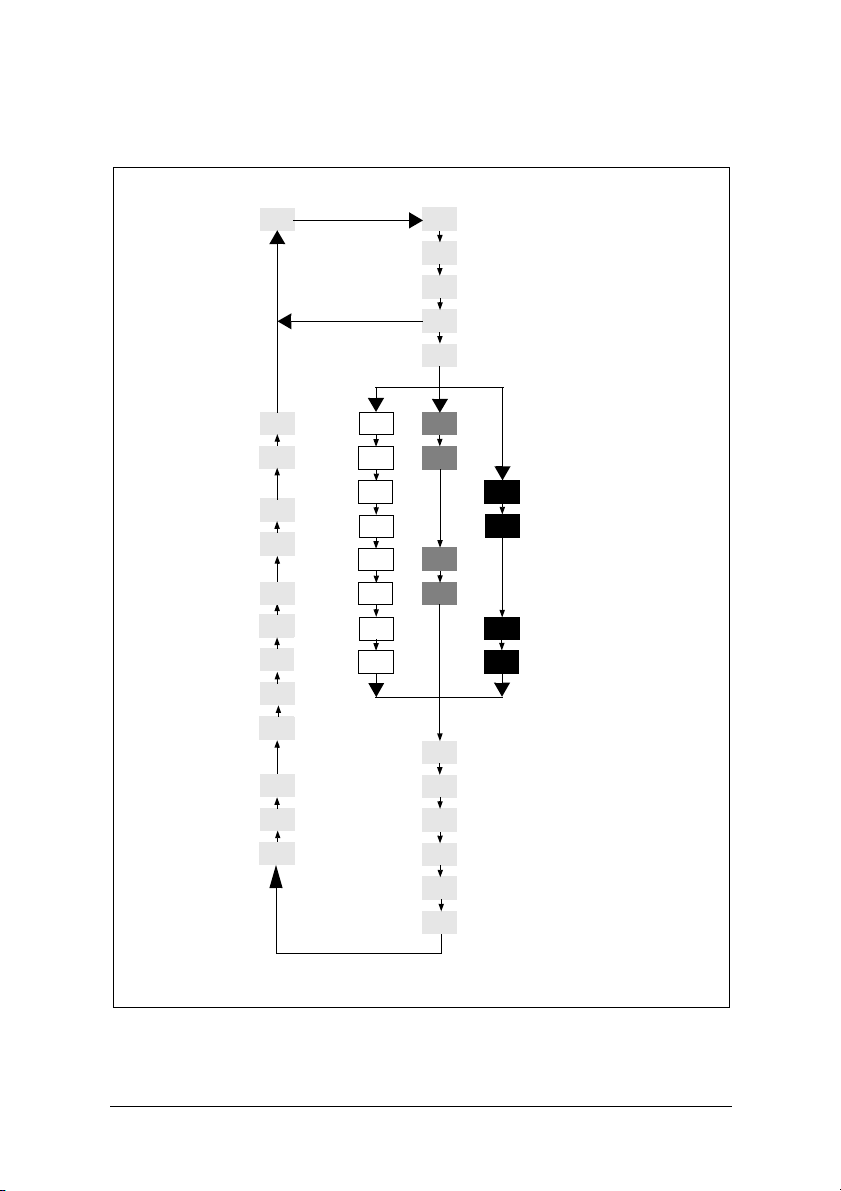
7.2 Window menu
Alarm indication
00
Start window
01
02
03
04
05
Measured shaft power
Measured line voltage
Measured current
Parameter Lock
Monitor Function
Factory defaults
Analogue Output
99
91
11
12
11
12
13
Block Timer
Digital Input
Relay function
Pre-Alarm Relay 2
Main Alarm Relay 1
Alarm at no motor
current
Main Alarm Latch
82
81
65*
64
63
62
61
14
21
OVER- and UNDERLOAD
22
21
OVERLOAD
22
UNDERLOAD
23
24
31
Number Of Phases
Rated Current
Rated Motor Power
43
42
41
32
33
34
35*
36*
* See Special functions in chapter 9, Advanced Features
MAX Main Alarm
MAX Pre-Alarm
13
MIN Pre-Alarm
MIN Main Alarm
14
MAX Main Alarm margin
MAX Pre-Alarm margin
MIN Pre-Alarm margin
23
MIN Main Alarm margin
24
Start Delay
Response Delay Max
Hysteresis
Response Delay Min
Pause/Reverse time
Autoreset (start attempts)
20 Operation Emotron AB 01-2551-01r4
Page 22

• The Alarm window only appears if an Alarm output is active.
NEXT
ENTER
NEXT
NEXT
ENTER
NEXT
• The Actual Load window appears after power up.
00
01
• Use the key to scroll through the menu. Scroll back by pressing and
holding at the same time as the key is pressed.
ENTER
• The Actual Load window (or alternative alarm window) will appear automatically if no keys are pressed for longer than 1 minute.
• If the Parameter Lock is on, only windows (if alarm active)
020403
01
• Window selects the monitor function, see section 8.4.
05
are visible.
00
7.3 How to c hange a value
Example: setting the rated motor current in window 42.
1. Press until the window number 42 appears.
42
5.6
A
2. Press or until the desired value is reached (e.g. 23 A), value flashes.
42
23
A
3. Press to confirm and save the change, value stops flashing.
NOTE: If the value is NOT to be changed, press the key.
CAUTION: In order to avoid personal injury, make sure that all safety
measures have been taken before switching on the supply voltage and
starting the motor/machine.
Emotron AB 01-2551-01r4 Operation 21
NEXT
Page 23

8Programming
8.1 Set measurement unit, kW or HP
8.1.1 Selecting the unit of measurement
The unit of measurement can be set to kilowatts or horsepower both as absolute
or relative values. This setting is valid for the alarm levels, rated motor power
and the actual load read-out in window 01.
Measurement
unit
Kilowatt relative value (def.)* % kW %
Horsepower absolute value HP HP HP
Horsepower relative value* % HP %
Kilowatt absolute value kW kW kW
Read-out
load
window 01
Rated power
window 41
Alarm levels
windows
11, 12, 13, 14
* Measured shaft power as % of rated power.
CAUTION: In order to avoid personal injury, make sure that all safety
measures have been taken before switching on the supply voltage and
starting the motor/machine.
22 Programming Emotron AB 01-2551-01r4
Page 24
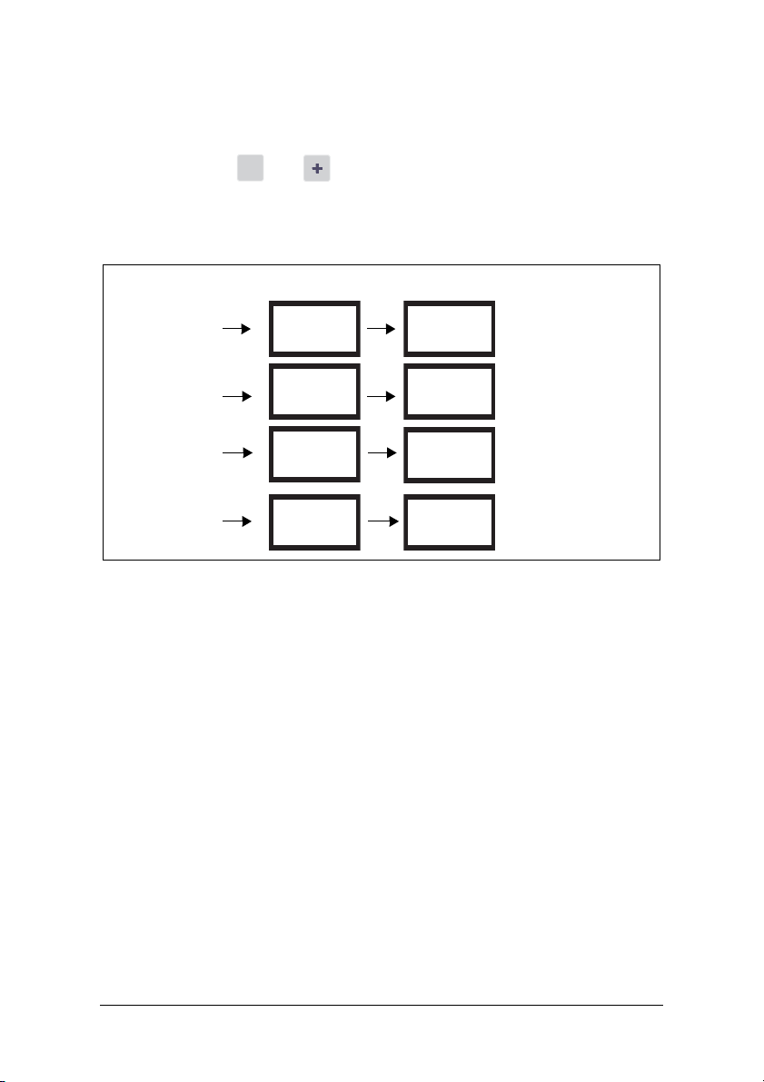
Programming
RESET
1. Go to window 01.
2. Press and hold and simultaneously for 3 seconds.
3. The next unit of measurement is set and appears for 2 sec (see examples).
Repeat to select the desired measurement unit according to the table.
Horsepower:
absolute value
RESET
For 2 seconds Read-out example
HP
01
3.52
Horsepower:
relative value*
Kilowatt:
absolute value
Kilowatt:
relative value*
(default)
HP
kW
kW
%
* Measured shaft power as % of rated power.
01
01
01
12
%
4.62
kW
12
%%
Emotron AB 01-2551-01r4 Programming 23
Page 25

8.2 Setting rated motor power and current
ENTER
ENTER
(window 41 and 42)
The rated motor power and the rated motor current must be set in windows 41
and 42.
Example motor plate:
TYPE: T56BN/4 NR: 948287 Prot. IP: 54
Serv: S1 Cos ϕ: 0.78 Is. Cl:F
V:Y/Δ Hz HP kW RPM A:Y/Δ
240/415 50 3 2.2 1400 5.6/9.4
260/440 60 3 2.2 1680 5.8/9.1
ASYNCHRONOUS THREE-PHASE MOTORS
8.2.1 Programming
1. Go to window 41 (default = 2.2 kW).
2. Press or to set the rated motor power as indicated on the motor
plate (see example).
3. Press to confirm the change.
4. Go to window 42 (default = 5.6 A).
5. Press or to set the rated motor current as indicated on the motor
plate (see example).
6. Press to confirm the change.
24 Programming Emotron AB 01-2551-01r4
Page 26

8.3 Setting number of phases (window 43)
ENTER
The number of phases must be set according to the number of motor phases.
Default is 3 phases, see also chapter 5, Wiring.
8.3.1 Programming
1. Go to window 43 (default = 3PH).
43
3PH
2. Press or to set the number of phases to 1 if a single-phase motor is
used.
3. Press to confirm the change.
43
1PH
8.4 Monitor function (window 05)
Monitor
(Protection)
OVER- and UNDERLOAD (default)
OVERLOAD
UNDERLOAD
If separate output relays are required for overload and underload alarms, please
refer to chapter 9 and chapter 12.
Emotron AB 01-2551-01r4 Programming 25
Indication in
window 05
Alarm
MAX Main Alarm Relay 1 (NC): 6-7
MAX Pre-Alarm Relay 2 (NO): 6-8
MIN Pre-Alarm Relay 2 (NO): 6-8
MIN Main Alarm Relay 1 (NC): 6-7
MAX Main Alarm Relay 1 (NC): 6-7
MAX Pre-Alarm Relay 2 (NO): 6-8
MIN Pre-Alarm Relay 2 (NO): 6-8
MIN Main Alarm Relay 1 (NC): 6-7
Output Relay
(default)
Page 27

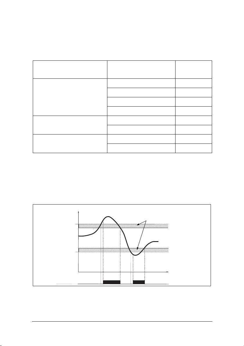
Overload and underload Monitor
ENTER
P/%
START UNDERLOAD OVERLOAD
MAX Main alarm
[11]
MAX Pre-alarm
[12]
OPERATION AREA
Auto set level
Normal load
MIN Pre-alarm
[13]
MIN Main alarm
[14]
Start delay [31]
Relay 1
Main alarm
Relay 2
Pre-alarm
Fig. 7 Overload and underload monitor.
Response
delay
[34] [32]
MAX Main
MAX Pre-alarm
margin [22]
MIN Pre-alarm
margin [23]
Main Alarm latch=ON [61]
alarm margin
[21]
MIN Main
alarm margin
[24]
t/s
Programming
1. Go to window 05. The default selection is Overload and Underload
monitor.
2. Press or to select underload or overload monitor.
_
05
_
OVER- and UNDERLOAD UNDERLOAD
3. Press to confirm the change.
26 Programming Emotron AB 01-2551-01r4
05
_
OVERLOAD
_
05
Page 28

8.5 Setting the Start Delay (window 31)
ENTER
To avoid false alarms during start up a Start Delay must be set to allow the
motor and machine to speed up and to allow the power in-rush currents.
Programming
1. Determine in seconds how long it takes for the motor and machine to reach
speed and for the power in-rush to pass. This will be the Start Delay.
2. Go to window 31 (default = 2.0 s).
3. Press or to set the determined Start Delay time in seconds.
4. Press to confirm the change.
If the monitor is being used on a self-priming pump, it may also be necessary to
set the Start Delay long enough to allow the pump to become fully primed.
Example: Start Delay 2.0 s
31
2.0
S
Fig. 8 Start Delay.
P
t
Start Delay [31]
Emotron AB 01-2551-01r4 Programming 27
Page 29

8.6 Setting alarm levels with Auto set
SET
AUTO
The Auto set command performs a measurement (momentarily) of the actual
motor load and automatically sets the relevant alarm levels depending on the
selected monitor function.
Protection
(Monitor
function
window 05)
OVER- and
UNDERLOAD
(Default)
OVERLOAD
UNDERLOAD
Alarm
MAX Main
Alarm
MAX PreAlarm
MIN PreAlarm
MIN Main
Alarm
MAX Main
Alarm
MAX PreAlarm
MIN PreAlarm
MIN Main
Alarm
Margin
Value
(Default
margins)
16%
8%
8%
16%
16%
8%
8%
16%
Margins
(Windows)
21: MAX Main
Alarm margin
22: MAX PreAlarm margin
23: MIN PreAlarm margin
24: MIN Main
Alarm margin
21: MAX Main
Alarm margin
22: MAX PreAlarm margin
23: MIN PreAlarm margin
24: MIN Main
Alarm margin
Alarm Level at
Auto set
Normal machine
load + Window 21
Normal machine
load + Window 22
Normal machine
load - Window 23
Normal machine
load - Window 24
Normal machine
load + Window 21
Normal machine
load + Window 22
Normal machine
load - Window 23
Normal machine
load - Window 24
Programming
1. Start the motor and let it run at the normal machine load until the Start
Delay has expired.
AUTO
2. Press for 3 seconds. This can be done in any window.
SET
28 Programming Emotron AB 01-2551-01r4
Page 30

3. The display shows “SEt”, to confirm that the Auto set level has been meas-
SET
AUTO
ENTER
ured and the alarm levels have been set. The display reverts to window 01.
3 seconds
AUTO
SET
SEE
01
40
%
4. If the alarm levels are too high or too low, readjust the appropriate MARGINS (see table) and perform a new Auto set. Alternatively, alarm levels can
be set manually, see chapter 9.
8.7 Setting the Response Delay (windows 32
and 34)
A Response Delay allows the machine to remain in an over- or underload condition for a specific time before the alarm relays are activated. Set the response
delay for the overload condition in window 32 (max.), and set the response
delay for the underload condition in window 34 (min.). The default value for
both windows are 0.5 s. The valves may be adjusted upwards to avoid triggering
a “false alarm”.
Programming
1. Determine in seconds the response delay required for both overload and
underload conditions. This is normally determined by the unique properties
and behaviour of each application.
2. Go to window 32 (overload, default = 0.5 s).
3. Press or to set the determined Response Delay time in seconds.
4. Press to confirm the change.
The response delay for the underload condition (min.) is set in window 34 in a
similar way.
Emotron AB 01-2551-01r4 Programming 29
Page 31

Example: Response Delay
32
0.5
S
P
Alarm level
34
0.5
S
Alarm
Fig. 9 Response Delay.
Response Delay [32]
t
30 Programming Emotron AB 01-2551-01r4
Page 32

9 Advanced Features
9.1 Setting alarm levels manually (windows
11-14)
The alarm levels can be set manually, without using the Auto set. These levels
can also be readjusted, e.g. for fine-turning, after an Auto set has been performed. See also section 4.3 to 4.6.
Protection (Monitor function
window 05)
OVER- and UNDERLOAD
(Default)
OVERLOAD
UNDERLOAD
Alarm levels (Window) Default
11: MAX Main Alarm 100%
12: MAX Pre-Alarm 100%
13: MIN Pre-Alarm 0%
14: MIN Main Alarm 0%
11: MAX Main Alarm 100%
12: MAX Pre-Alarm 100%
13: MIN Pre-Alarm 0%
14: MIN Main Alarm 0%
Emotron AB 01-2551-01r4 Advanced Features 31
Page 33
Setting margins (windows 21-24)
The margins for the Auto set can be changed manually. After the adjustment,
the Auto set action must be performed again.
Protection (Monitor function
window 05)
Window Default
21: MAX Main Alarm margin 16%
OVER- and UNDERLOAD
(Default)
22: MAX Pre-Alarm margin 8%
23: MIN Pre-Alarm margin 8%
24: MIN Main Alarm margin 16%
OVERLOAD
UNDERLOAD
21: MAX Main Alarm margin 16%
22: MAX Pre-Alarm margin 8%
23: MIN Pre-Alarm margin 8%
24: MIN Main Alarm margin 16%
Setting hysteresis (window 33)
The hysteresis of an alarm level prevents the alarm relay “chattering” if the load
fluctuates even in a normal “stable” condition. This also applies to a pre-alarm.
This feature is normally only used if the main alarm latch (window 61) is set to
Off. Default = 0%.
P/%
MAX Main Alarm level [11]
Hysteresis [33]
MIN Main Alarm level [14]
t/s
Relay 1 MAIN Alarm
Fig. 10 Hysteresis
32 Advanced Features Emotron AB 01-2551-01r4
Page 34

Setting main alarm latch (window 61)
The main alarm latch keeps the main alarm output active, even if the alarm condition has been removed. A latched alarm output can be reset by:
•The reset key
• External reset via digital input (see window 81).
• Switching off the power to the monitor (see also Wiring).
Default = Off.
Setting alarm at no motor current (window 62)
The alarm at no motor current gives an alarm if the motor current goes down to
zero (62 = on). Default = Off (No alarm at no motor current).
Setting relay output (window 63 and 64 alt. 65)
The relay outputs R1 and R2 can be set to NO or NC contacts.
NOTE: If the power to the load monitor is switched off, the relay contacts
are always in position NO.
If separate output relays are required for overload (max., relay R1) and underload (min., relay R2), see Special functions in chapter 9 and chapter 12.
Setting digital input (window 81)
The digital input can be set for:
RES: External RESET
(Default)
AU: External Auto set To perform an Auto set with an external signal.
bLo: Block Pre-Alarm
Emotron AB 01-2551-01r4 Advanced Features 33
To reset an alarm.
To block the Pre-Alarm function and start the Block
timer. If the input is high a Pre-Alarm is blocked, i.e. it is
neglected. See also window 82.
Page 35
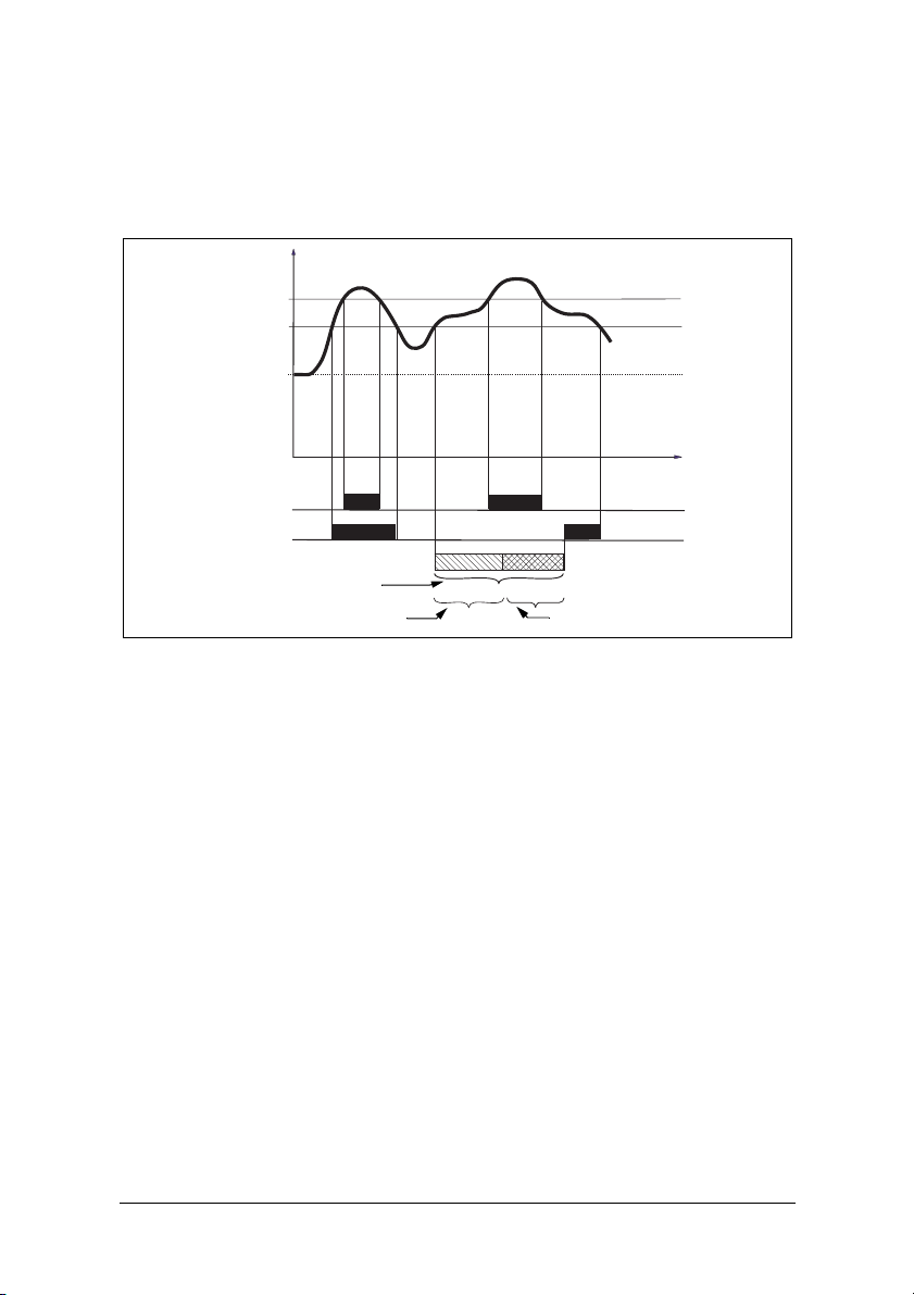
Setting block timer (Window 82)
To set the timer for the blocking time after the Block command is released (see
also window 81). Default = 0.0 sec.
P/%
MAX Main Alarm level [11]
MAX Pre-Alarm level [12]
Auto set level
t/s
Relay 1 Main alarm
Relay 2 Pre-alarm
Pre-Alarm Blocked
Block signal high on terminal 5 DIG [81] Block timer [82]
Fig. 11 Block timer
Setting analogue output (window 91)
The analogue output provides an analogue signal of either 0-20 mA or 4-20 mA
which represents the motor shaft power. The signal can be inverted (20-0 or 204 mA). Full scale: rated motor power, see Fig. 12. To set P-span/scaling (full
scale) see Fig. 13.
34 Advanced Features Emotron AB 01-2551-01r4
Page 36

91
P
SHAFT
100%
4.20
20.4
20.0
0.20
0%
Fig. 12
4.20
04 20
Output
mA
Emotron AB 01-2551-01r4 Advanced Features 35
Page 37
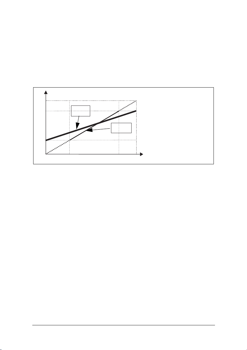
Setting analogue output load range: P-span (window
92-93)
With windows 92 and 93 the full scale of the analogue output can be set according to the minimum and maximum load (P-span).
1. In window 91, press RESET and + for two seconds until “on” shows. Windows 92 and 93 are now active.
P shaft
100%
70%
20%
92= 20%
93= 70%
92= 0%
93= 100%
0
0
6
14
20
Output
mA
Fig. 13
2. Set the lowest load value in window 92 (e.g. 20%)
3. Set the highest load value in window 93 (e.g. 70%)
The full scale of the analogue output is now set between 20% and 70% load.
See Fig. 13. To deactivate: Press RESET and + for two seconds until “Off”
shows in window 91.Windows 92 and 93 are now inactive.
Locking parameters (window 04)
To avoid the parameter settings being changed unintentionally, the programming can be locked by entering the code “369” in window 04. Now only Load
[01], Voltage [02] and Current [03] can be checked. Follow the same procedure
to unlock the monitor. The Auto set key is disabled when parameters are locked.
Auto set via digital input is always active if window 81 is set to AU (Auto set).
36 Advanced Features Emotron AB 01-2551-01r4
Page 38

01
24
%
NOTE: The symbol appears in all windows.
Resetting to factory defaults (window 99)
The factory defaults are reset by entering “dEF” in window 99. If window 99
shows “USr” it indicates that the settings have been changed to user specific settings.
View alarm message (window 00)
In an alarm condition, the window 00 appears automatically. The window indicates the following alarm conditions. Window 00 flashes at all times.
Undervoltage,
switch off the
supply!
Overvoltage,
switch off the
supply!
No motor current
Window 62 = on
00
00
00
!
F
!
F
!
FO
^
^
Pre-Alarm MAX
level reached
Alarm MAX
level reached
Pre-Alarm MIN
level reached
00
00
00
!
LU
!
0U
!
F0
Out Of Range. This message
appears only in window 01 (actual
load) or 03 (actual current)
00
!
FO
Alarm MIN
level reached
01
!
OOO
When the monitor is switched on (power up), the voltage on phases L1, L2 and
L3 is checked. If the wrong voltage is detected, an LU (undervoltage) or OU
(overvoltage) alarm is generated. No relay alarm will be indicated or activated.
Emotron AB 01-2551-01r4 Advanced Features 37
Page 39
Special functions (windows 35, 36 and 65)
Special functions are separate relays for overload and underload alarm/stop, start
attempts and a reverse function with start attempts:
• Window 65 = 0, Normal M20
• Window 65 = 1, Separate relays for overload and underload alarm (DLM)
• Window 65 = 2, Reverse function
Window 65 = 0
“Normal M20”
R1
R2
Max/Min
Main alarm
Max/Min
Pre-alarm
Window 65 = 1
“Separate relays
over-/underload
alarm” (max/min)
R1
R2
Max
Main alarm
Min
Main alarm
Window 65 = 2
“Reverse function”
R1
R2
Forward
Reverse
Fig. 14 Window 65 and relay functions
In all three cases the number of start attempts after a main alarm may be set in
window 36. The pause time between start attempts may be set in window 35.
This time is also used as the time to run the motor in the reverse direction when
window 65=2.
The reverse function can be used to reverse e.g. a screw conveyor or pump when
a “jam” occurs. Reversing the motor may remove the blockage. Should one
reverse cycle not be enough to release the material, the M20 will repeat this
operation up to a maximum of 5 cycles (window 36, 0-5 start attempts). Relay
R1 = forward, relay R2 = reverse.
NOTE: For special handling of analogue output in reverse mode, see below.
The analogue output will go to its maximum e.g. 20 mA when the number of
allowed start attempts has elapsed.
Resetting an alarm
A reset will cause the start attempt counter to be reset (new start attempts may
be performed).
38 Advanced Features Emotron AB 01-2551-01r4
Page 40
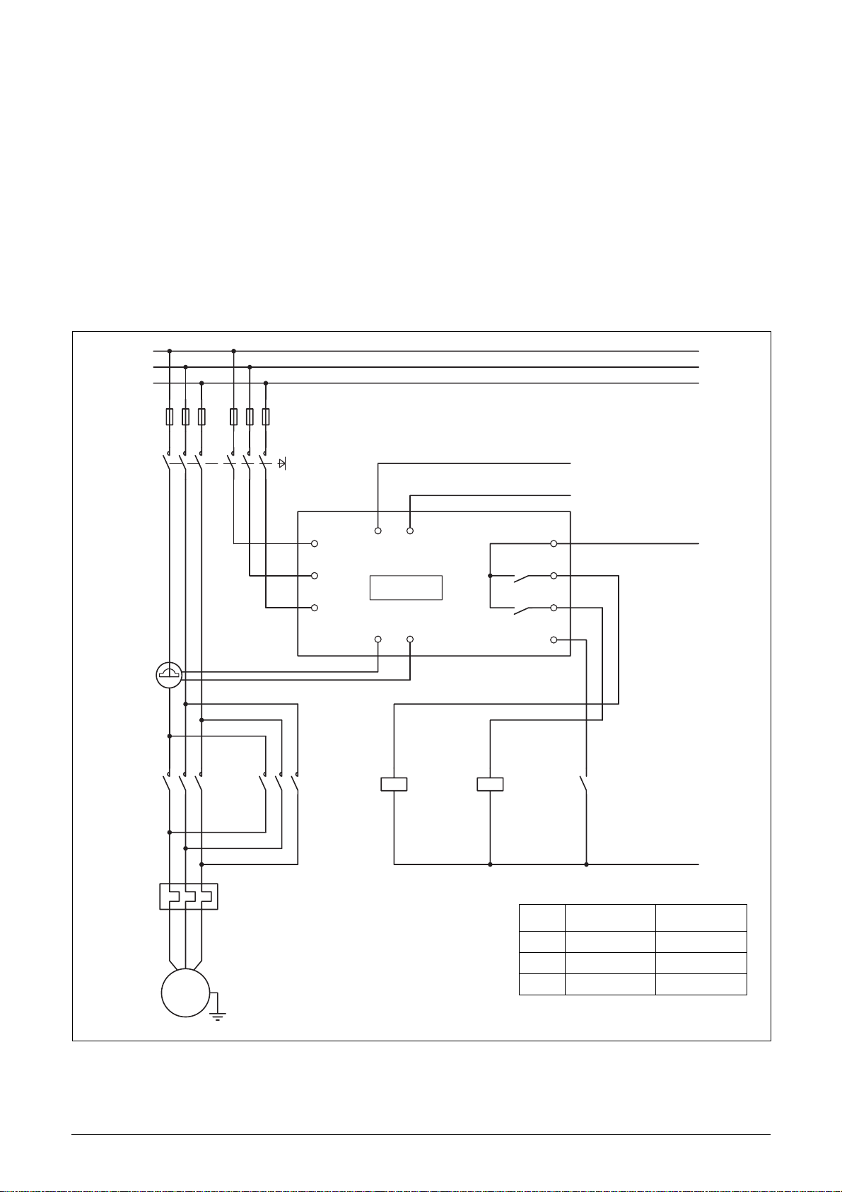
NOTE: In order to accomplish the above result, it will be necessary for a
forward and reversing motor starter to be installed. See Fig. 15 Example of
connection with a forward and reversing motor starter (contactor).
For more information contact your local sales outlet or visit us at:
www.emotron.com
L1
L2
L3
Alarm/Stop
20 mA
}
(Blocking)
Max 240 VAC (alt. 0 VDC-)
6
7
8
5
CTMxxx
9
3
M20
S1 S2
1
4
A-A+
2
L1 C
11
L2
13
L3
R1
R2
DIG
K1
K2
UVW
M
K1 K2 Reset
FWD
Window Function Range
35 Reverse time 3-90 s
36 Star t attempts 0-5
65 Relay function 2=reverse
REV
N (alt. 48 VDC+)
Fig. 15 Example of connection with a forward and reversing motor starter (contac-
tor).
NOTE: In Fig. 15, R1 and R2 (K1 and K2) must not be energized/on at the
same time as this will generate a short circuit. Therefore it is important
that window 65 = 2 before the relays are connected to the contactors.
Emotron AB 01-2551-01r4 Advanced Features 39
Page 41
Alternative auxiliary circuit
L1
L2
L3
CTMxxx
UVW
9
3
4
L1
A+ A-
11
L2
M20
13
L3
1
C
R1
R2
S2S1
2
DIG
6
7
8
5
0VDC-
OUT
24VDC+
M
Fig. 16 Example of auxiliary circuit when VDC is used.
The example above can be used when a high VDC signal output is required.
40 Advanced Features Emotron AB 01-2551-01r4
Page 42

10 Troubleshooting
Ensure that the installation has been correctly carried out, e.g. check the terminals and that the cables are properly stripped. The monitor is maintenance-free.
However, you should regularly check wirings and terminals etc.
Problem Solution
- Check the connection of the current
transformer(s).
Window 01 always
shows zero load, even if
the motor is running
Window 01 shows an
improper power value
when the motor is running
Window 03 shows an
improper value for the
phase current
The monitor never gives
an alarm
- Check that the value of the rated motor power in
window 41 is the same as the rated motor power on
the motor plate.
- Check that window 03 shows a phase current
value that agrees with with the rated motor
current.
- Check that the motor is not oversized for its application, check power transmission and gear ratio.
- Check that there is a load on the motor during
normal operation.
- Check that the change in motor load is greater than
about 3% (window 01).
- Check that the current transformer is connected in
phase L1.
- Check that the current transformer has been
selected as per Tables 1 and 2.
- Check that the number of windings is as per Tables
1 and 2.
- Check that the value of the motor current in
window 42 is the same as the value of the motor
current on the motor plate.
- Check that window 01 shows a value greater than
zero.
- Check the alarm levels in windows 11 to 14. If incorrect readjust the levels or perform an Auto set.
Emotron AB 01-2551-01r4 Troubleshooting 41
Page 43

Problem Solution
- Check the alarm levels in windows 11 to 14.
If incorrect readjust the levels or perform an
The monitor always
gives an alarm
Window 00 shows “LU”
or “OU”. Under- or overvoltage alarm.
Window 01 shows
“oor”. “Out Of Range”
alarm.
Window 03 shows
“oor”. “Out Of Range”
alarm.
Over and undervoltage
is not detected
The alarm relays are not
switching
Not all windows are
shown
Auto set.
- Check if the monitor is programmed for “latched
alarm” (window 61=on). If so reset the monitor by
pressing the reset key.
Switch off the supply:
- Check that the supply voltage agrees
with the voltage range on the monitor type plate.
- The measured shaft power is higher than 125% of
the rated motor power programmed in window 41.
- The measured motor current is higher than 125%
of the rated motor current programmed in window
42.
This is only detected at monitor power up and not during continued operation. The relays will not trip, only
indication in the display.
- Check that the wire links between terminals 6
and 7 are removed as per “Wiring”.
When the special functions are used (windows 35, 65
etc.) blocked windows for settings are not shown.
42 Troubleshooting Emotron AB 01-2551-01r4
Page 44

11 Technical Data
45x90x115 mm (1.77" x 3.54" x 4.53")
Dimensions
35mm
(WxHxD)
45mm (1.77’‘)
(1.38)’‘
26mm
(1.02)’‘
115mm(4.53) ’‘
Mounting 35 mm DIN rail 46277
Weight 0.30 kg (10.5 oz)
Supply voltage
(±10%)
1x100-240 VAC, 3x100-240 VAC, 3x380-500 VAC or 3x525690 VAC
Frequency 50 or 60 Hz
Current input
Power consumption
Current transformer; CTM 010, 025, 050 and 100. Input 055 mA. (>100 A extra transformer needed)
Max. 6 VA
Start-up delay 1-999 s
Hysteresis 0-50% of rated motor power
Response delay
max
Response delay
min
0.1-500 s
0.1-500 s
Relay output 5 A/240 VAC Resistive, 1.5 A/240 VAC Pilot duty/AC12
Analogue output Max. load 500 ohm
Digital input
Max. 240 VAC or 48 VDC. High: ≥24 VAC/DC,
Low: <1 VAC/DC. Reset >50 ms
Fuse Max. 10 A
2
single core
Terminal wire size
Use 75°C copper (CU) wire only. 0.2-4.0 mm
(AWG12). 0.2-2.5 mm
2
flexible core (AWG14), stripped
length 8 mm (0.32")
’‘
90mm(3.54)
Emotron AB 01-2551-01r4 Technical Data 43
Page 45

Ter minal tig htening torque
Accuracy
Repeatability ±1 unit 24h; +20°C (+68°F)
Temperature tolerance
Operating temperature
Storage temperature
Protection class IP20
RoHS directive 2002/95/EC
Approved to CE (up to 690VAC), UL and cUL (up to 600 VAC)
0.56-0.79 Nm (5-7 lb-in)
±2%, ±1 unit cos phi>0.5; excl. current transformer; +20°C
(+68°F)
max 0.1%/°C
-20 to +50°C (-4°F to +122°F)
-30 to +80°C (-22°F to +176°F)
Article
number
01-2520-20 Emotron M20 1x100-240/3x100-240 VAC
01-2520-40 Emotron M20 3x380-500 VAC
01-2520-50 Emotron M20 3x525-690 VAC
Designation
Technical Data for Current Transformer (CT)
Type
CTM 010 27 (35) x Ø48 mm 0.20 kg 35mm DIN rail 46277
CTM 025 27 (35) x Ø48 mm 0.20 kg 35mm DIN rail 46277
CTM 050 27 (35) x Ø48 mm 0.20 kg 35mm DIN rail 46277
CTM 100 45 (58) x Ø78 mm 0.50 kg 35mm DIN rail 46277
44 Technical Data Emotron AB 01-2551-01r4
Dimensions
(WxØ)
Weight* Mounting
Page 46
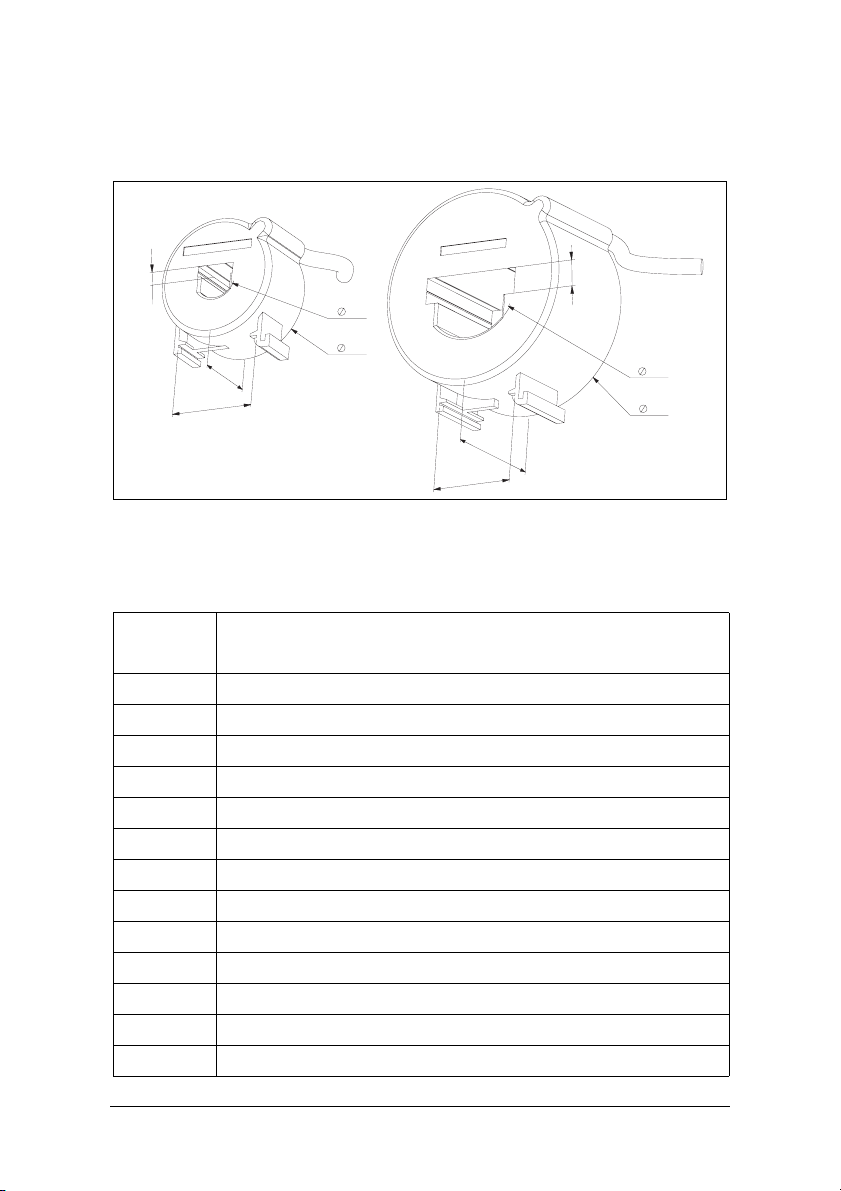
* Weight including 1m (39 inch) cable. Please note that max. length of the
CTM cable is 1 m and this cable cannot be extended.
4.3
17
27
35
48
45
35
Fig. 17 Current Transformer CTM xxx.
Accessories and documentation
Article
number
01-2471-10 Current Transformer (CT) CTM010, max. 10 A
01-2471-20 Current Transformer (CT) CTM025, max. 25 A
01-2471-30 Current Transformer (CT) CTM050, max. 50 A
01-2471-40 Current Transformer (CT) CTM100, max. 100 A
01-2368-00 Front Panel Kit 1 (2x terminal covers included)
01-4136-01 2x Terminal covers
01-2551-00 Instruction manual (Swedish)
01-2551-01 Instruction manual (English)
01-2551-02 Instruction manual (German)
01-2551-03 Instruction manual (Dutch)
01-2551-04 Instruction manual (Spanish)
01-2551-08 Instruction manual (French)
01-2551-09 Instruction manual (Russian)
Designation
10.3
42
78
Emotron AB 01-2551-01r4 Technical Data 45
Page 47

Dismantling and disposal
The product is designed to comply with the RoHS directive, and shall be handled and recycled in accordance with local legislations.
EU (European Union) specifications
EMC EN 61000-6-3, EN 61000-6-2
EN 61000-4-5
Electrical safety EN 60947-5-1
Rated insulated voltage 690 V
Rated impulse withstand voltage 4000 V
Pollution degree 2
Terminals 3, 4, 5, 6, 7 and 8 are basic insulated from the line.
Terminals 3 and 4 are basic insulated from terminals 5, 6, 7 and 8.
US specifications
FCC (Federal Communications Commission). This equipment has been tested
and found to comply with the limits for a Class A digital device pursuant to Part
15 of the FCC Rules. These limits are designed to provide reasonable protection
against harmful interference when the equipment is operated in a commercial
environment. This equipment generates, uses and can radiate radio frequency
energy and, if not installed and used in accordance with the instruction manual,
may cause harmful interference, in which case the user will be required to correct the interference at their own expense.
Canadian specifications
DOC (Department of Communications). This digital apparatus does not
exceed the Class A limits for radio noise emissions from digital apparatus as set
out in the Canadian Interference-Causing Equipment Regulations. Le présent
appareil numérique n'ément pas de bruits radio-électriques dépassant les limites
applicables aux appareils numériques de la Classe A prestite dans le Régelement
sur le brouillage radioélectrique édicté du Canada.
46 Technical Data Emotron AB 01-2551-01r4
Page 48

12 Parameter List
Window Function Range Default Custom Symbol
00 Alarm indication
Measured shaft
power in % of rated
power
Measured shaft
01
02 Measured line voltage 90-760 V V
03 Measured current 0.00-999 A A
04 Parameter lock 0-999
05 Monitor function
11
12
power in kW
Measured shaft
power in % of rated
power
Measured shaft
power in HP
MAX Main Alarm (relay
R1)
MAX Pre-Alarm (relay
R2)
0-125 %
0-745 kW
0-125 %
0-999
OVER- and
UNDERLOAD,
OVERLOAD,
UNDERLOAD
0-125 100 %
0-745 2.2 kW
0-125 100 %
0-999 3
0-125 100 %
0-745 2.2 kW
0-125 100 %
0-999 3
OVERLOAD
and UNDERLOAD
Emotron AB 01-2551-01r4 Parameter List 47
Page 49

Window Function Range Default Custom Symbol
0-125 0 %
13
14
21
22
23
24
31 Star t d el ay 1-999 2 s
32
33 Hysteresis 0-50 0 %
34
35* Pause/Reverse time 3-90 5 s
36*
41 Rated m oto r po wer
42 Rated current 0.01-999 5.6 A
43 Number of phases 1PH/3PH 3PH
61 Main alarm latch on/OFF OFF
MIN Pre-Alarm (relay
R2)
MIN Main Alarm
(relay R1)
MAX Main Alarm
margin
MAX Pre-Alarm
margin
MIN Pre-Alarm
margin
MIN Main Alarm
margin
Response delay overload
Response delay
underload
Autoreset (start
attempts)
0-745 0 kW
0-125 0 %
0-999 0
0-125 0 %
0-745 0 kW
0-125 0 %
0-999 0
0-100 16 %
0-100 8 %
0-100 8 %
0-100 16 %
0.1-500 s 0.5 s
0.1-500 s 0.5 s
0-5 0
0.10-745 2.2 kW
0.13-999 3
48 Parameter List Emotron AB 01-2551-01r4
Page 50

Window Function Range Default Custom Symbol
62
63 Main Alarm relay R1 nc/no nc
64 Pre-Alarm relay R2 nc/no no
65* Relay function
81 Digital input rES/AU/bLo rES
82 Block timer 0.0-90 0.0 s
91 Analogue output
92**
93**
99 Factory defaults dEF/USr dEF
Alarm at no motor
current
Analogue output low
value
Analogue output high
value
on/OFF OFF
0 = M20
1 = DLM
2 = Reverse
0.20/4.20/
20.0/20.4
0-100
0-125
0
0.20
* See Special functions in chapter 9.
** See Set analogue output range in chapter 9.
Emotron AB 01-2551-01r4 Parameter List 49
Page 51

13 Service
This manual is valid for the following model:
Emotron M20 (from software version R3b)
Document number: 01-2551-01
Document version: r4
Date of release: 2008-05-15
Emotron AB reserves the right to alter product specifications without prior
notification. No part of this document may be reproduced without permission
from Emotron AB.
For more information contact your local sales outlet or visit us at:
www.emotron.com
Protected by utility patents EP 1027759 and US 6879260
50 Service Emotron AB 01-2551-01r4
Page 52

Emotron AB, Mörsaregatan 12, SE-250 24 Helsingborg, Sweden
Tel: +46 42 16 99 00, Fax: +46 42 16 99 49
E-mail: info@emotron.se
Internet: www.emotron.com
Emotron AB 01-2151-01r4 2008-05-15
Page 53
Emotron M20
Reverse function
Addendum
English
Page 54

Emotron M20 Shaft Power Monitor
Special functions (windows 35, 36
and 65) ”Reverse function”
This instruction is valid for Emotron M20, 01-2551-01,
(from software version R3B).
The reverse function can be used to reverse (drive backwards) motor driven equipment such as e.g. a screw conveyor when a “jam” occurs. With this function the M20 can
be used to prevent expensive stops and breakdowns in
machinery for example; blocked chip feeder, jammed lime
feeder, blocked slurry pump or in other similar applications.
In the case of a screw conveyor or chip feeder, for instance,
when an overload or jam-up occurs, the Emotron M20
reverses the “conveyor” automatically. Normally this would
clear the jammed material and then enable the conveyor to
feed forward again.
Should one reverse cycle (drive backwards) not be enough to
release the material, the monitor will repeat this operation
up to a maximum of five start attempts. If the conveyor is
still jammed, the monitor stops the conveyor motor/
machine from any further operation and an alarm is given.
The conveyor would then have to be cleaned manually and
the monitor reset. The number of start attempts and the
reverse time can be set. If set number of start attempts is
enough to release the material the conveyor will feed forward
again, and reset the previous number of start attempts, but
only after the conveyor has fed forward for least 60 seconds
if the selected start and response delay time has elapsed.
and
Wiring, Programming and Operation
CAUTION: Study thoroughly section 2 Safety in the Emotron
M20 Instruction manual before installing and using the
monitor. Please note that the machine starts and stops
automatically during set-up and running when the reverse
function is used!
For wiring, programming and operation see the corresponding sections in the Installation manual for the M20. See also
under 9 Advanced Features and the headline Special functions (windows 35, 36 and 65) as well as the special connection example in Figure 1 (this example can also be found at
the end of this instruction).
NOTE:
To implement the above Reverse function, it will be
necessary for a forward and reversing motor starter
(contactors) to be installed.
Relay R1 and R2 (K1 and K2) must not be energized/on at
the same time as this will generate a short circuit.
Therefore it is important that window 65 = “2” before the
relays are connected to the contactors and it is also
recommended that the Forward and Reverse contactors
are also electrically interlocked.
The output relay contacts, terminals 6, 7 and 8 connect to
the motor control circuit and to the respective contactor; i.e.
terminal 7 to K1 (R1) = Forward and terminal 8 to K2 (R2)
= Reverse (see fig. 1). Terminal 5 can be used for external
reset and has the same function as the reset button on the
front of the monitor.
Analogue output
In this Reverse function application the analogue output will
go to its maximum 20 mA when the number of allowed start
attempts has elapsed. The output signal can for example be
used as an input to PLC´s or similar equipment to handle
the alarm etc. If a potential free relay contact is required, the
following external relay is recommended as an accessory:
• Schrack / Tyco RT174012 12 VDC (10A 250VAC)
• Camden DIN-rail relay socket C 250 3P
Please note that an external alarm relay connected to the
analogue output must be specified as the above relay coil
voltage, resistance, power etc to ensure correct operation
and life time.
Set the monitor as follows
(First perform settings according to the applicable parts of
the M20 Monitor installation manual):
1. In this application it is unusual that both overload and
underload monitoring is used and unless the underload
is required in some other function window 5 should be
-
set to monitor overload only (
).
2. Start the motor/machine and let it run at normal load
until the start delay has elapsed - the machine load is
shown in the monitor display.
3. Press the “Auto set” button for 3 seconds.
4. Adjust start attempts (window 36), start delay (window
31), response delay (window 32, alt 34 at min), reverse
time (window 35) etc. as required.
It is also possible to set the alarm level manually, see the
manual and chapter 4 Getting Started.
Operation – Alarm
When an overload occurs for longer than the selected
response delay (window 32), the following sequence takes
place if there are still some start attempts available:
1. Motor is switched-off and stands for 3 seconds.
2. Motor is reversed during chosen reversal time, window
35 (If the monitor senses an overload during reversal the
motor will stop).
3. Once again, the motor is switched-off and stands for 3
seconds.
4. Motor re-starts automatically in forward mode.
For a prolonged jam-up, the monitor will carry out the maximum of reverse cycles set in window 36. If this does not
clear the blockage, the motor is switched-off and the analogue output will go to its maximum 20 mA “permanent”
stop and alarm. When this occurs, the conveyor/machine
must be cleaned manually and the monitor reset, either by
1 Emotron AB 01-4481-01r1
Page 55
the reset button or by the digital input. When reset, the
monitor can once again perform the number of reverse
cycles set in window 36.
Reset of the monitor can be done in three ways:
• Reset button
• Digital input, set for “rES”, window 81
• Switch-off the supply voltage, 3-phase.
Important! If the monitor senses an overload during reversal,
after start and response delay has elapsed, the motor will be
stopped immediately even if the reversal time is set for a
longer time. The monitor will then try to run in the forward
direction again. If the load returns to a normal running level
before the start delay has elapsed (i.e. the jammed material
L1
L2
L3
clears), the monitor will reverse the motor/feeder until the
selected time has concluded.
If the reversal time is set to a shorter time period than the
start and response delay together, the reverse mode will be
completed after the selected reverse time has concluded,
independently of the set response delay. In this case the
response delay only has an effect on forward running.
When the conveyor has fed forward for at least 60 seconds
with normal conditions and no alarm, the previous number
of start attempts (reverse cycles) are reset automatically
although only if selected start and response delay time has
concluded.
Alarm/Stop
20 mA
}
(Blocking)
CTMxxx
K1
UVW
M
K2
9
11
3
L1 C
4
A-A+
L2
M20
13
L3
S1 S2
2
1
K1 K2 Reset
FWD
R1
R2
6
7
8
5
DIG
REV
Window Function Range
35 Reverse time 3-90 s
36 Start attempts 0-5
65 Relay function 2=reverse
Max 240 VAC (alt. 0 VDC-)
N (alt. 48 VDC+)
Fig. 1 Example of connection with a forward and reversing
motor starter (contactor).
Emotron AB 01-4481-01r1 2
Page 56

Emotron AB, Mörsaregatan 12, SE-250 24 Helsingborg, Sweden
Tel: +46 42 16 99 00, Fax: +46 42 16 99 49
E-mail: info@emotron.se
Internet: www.emotron.com
Emotron AB 01-4481-01r1 06-30-2008
 Loading...