

Page 1
J1000
J1000
J1000
J1000
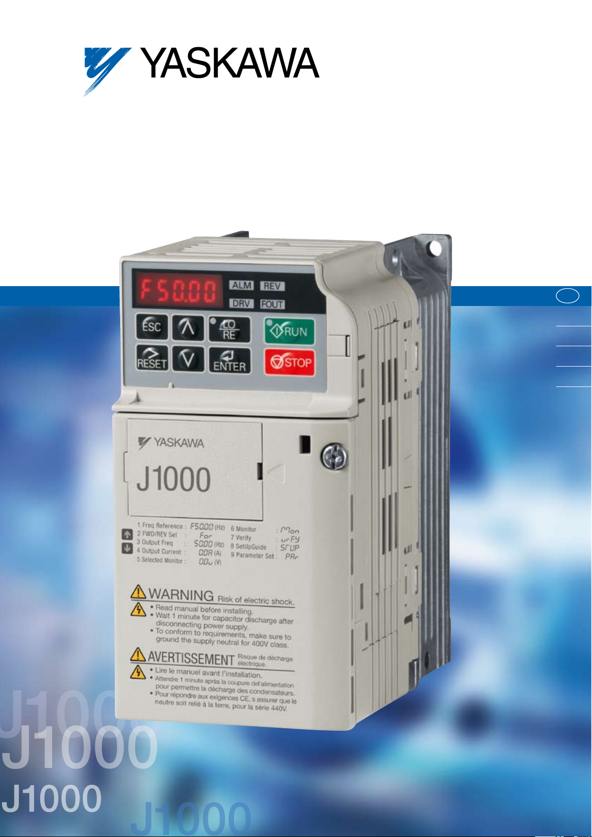
COMPACT INVERTER SERIES
J1000
E N
DE
ES
FR
IT
Page 2
2
YASKAWA J1000
Content
Contents
THE J-TYPE
YASKAWA INVERTER DRIVE TECHNOLOGY
Page 2
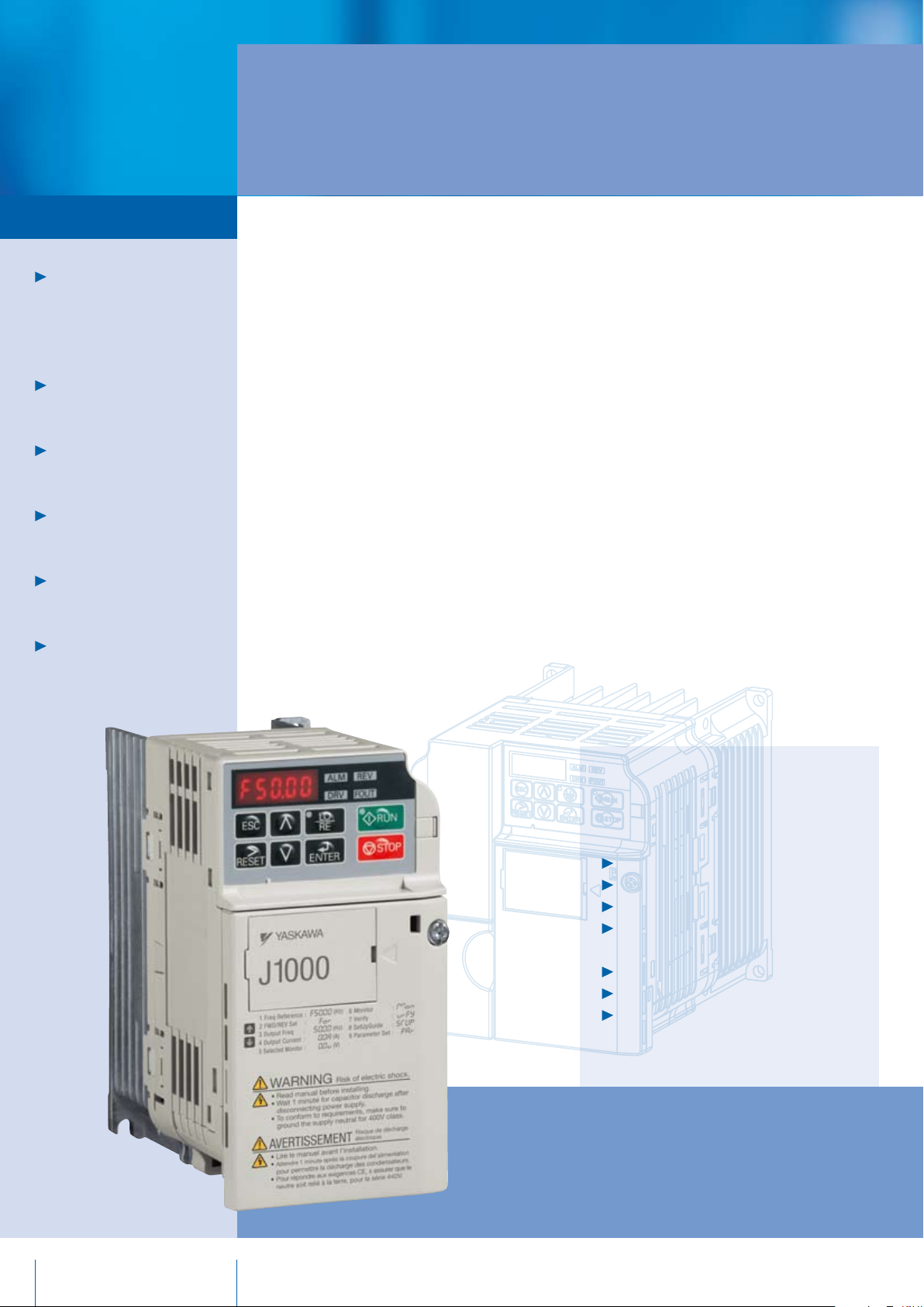
Experience & Innovation
A leader in Inverter Drives
technology
Page 3
Features & Functions
Page 4
Specifications
Page 5
Connection Diagram
Page 6
Dimensions
Page 7
Ratings & Type Descriptions
Experience & Innovation
For more than 90 years YASKAWA has
been manufacturing and supplying
mechatronic products for machine
building and industrial automation.
A leader in Inverter Drives
technology
Extensive research and development
has allowed YASKAWA to remain at the
forefront of motion control and automation
technology. This technological leadership
has helped to modernise industries such
as mining, steel, pulp and paper, chemical,
automotive, packaging, machine tool and
semiconductor.
Its standard products as well as tailormade solutions are famous and have a
high reputation for outstanding quality
and durability.
The famous YASKAWA reliability is now
available in an even smaller and more
powerful unit.
J1000 is fully capable of efficient
performance and energy saving,
handling variable speed needs in
compact applications.
The J1000 cutting-edge
features such as:
V/f Control
Plug’n Play installation function
Over-Excitation Braking
Easy parameter programming and
controller functions
Braking Chopper
Heavy duty / normal duty rating
International standards
Page 3

3
Focus on application
Customer orientation and application focus –
two attributes of machine equipment
YASKAWA offers with its new J1000
compact inverter drive series.
The J1000 meets all automation requirements for compact applications with variable
speed operation and energy saving characteristics. A wide range of useful functions
upgrade your machine and offer great
potentials.
The concept of small size and easy handling
with the famous YASKAWA reliability makes
the J1000 an alternative in the drive market
not only cost wise.
Conveyor
Hoist
Escalator
Pump
Crane
Fan
Features & Functions
Grinder
Screw Feeder
Drilling
YASKAWA J1000 Features & Functions
Performance
Compact Design – Small design and
side-by-side mounting reduce installation
space and costs.
Stall Prevention Functions –
Stall prevention ensures stabile operation
during momentary power loss, change of
load or power supply.
International Standards – RoHS, CE, cUL,
UL compliance.
High Torque Performance – Detects
load and automatically adjusts torque
regardless the actual speed conditions.
Digital Operator – 5 digit display, 8 keys on
the operator as well as Verify Function for
changed parameter values.
Options
Parameter Copy Unit
Optional LED Remote Operator
Serial Communication Option – Compatible
with RS-422/485 Interface for MEMOBUS
communication.
Speed Potentiometer
Functions
Easy Set-Up Functions – Enables quick
installation and operation.
Over-Excitation Braking – For quick
deceleration without external braking
resistor.
Maintenance monitor informs in advance
about recommended maintenance for
cooling fan and electrolytic capacitors.
Small Design – Big Power:
150% overload in heavy duty service
is possible. For applications with low
overload requirements the drive can be
operated with 120% overload in normal
duty service. Consequently you can use
a drive of smaller size to do the work of a
bigger one.
Tough Operation – Power-Loss-Ride-
Through and Fault Restart Functions
ensure continuous running of the motor.
Drive Wizard Plus – Free of charge
parameter set-up and maintenance tool.
Page 4

4
YASKAWA J1000
Specifications
Specifications
Control methods V/f Control
Frequency Control Range 0.01 to 400 Hz
Frequency Accuracy
(Temperature Fluctuation)
Frequency Setting
Resolution
Output Frequency Resolution 1/2
Frequency Setting Signal Main frequency reference: 0 to +10 Vdc (20 kΩ), 4 to 20 mA (250 Ω), 0 to 20 mA (250 Ω)
Starting Torque 150% / 3 Hz
Speed Control Range 1:20
Accel/Decel Time 0.0 to 6000.0 s (4 selectable settings of independent acceleration and deceleration time)
Control Characteristics
Braking Torque
V/f Characteristics User-set programmable V/f preset patterns possible
Main Control
Functions
Motor Protection Motor overheat protection based on output current
Momentary Overcurrent Protection Drive stops when output current exceeds 200% of Heavy Duty Rating
Overload Protection Drive stops after 60 s at 150% of rated output current (Heavy Duty Rating)*
Overvoltage Protection
Undervoltage Protection
Momentary Power Loss Ride-Thru Stops after approx. 15 ms (default).
Heatsink Overheat Protection Protected by thermistor
Protection Function
Braking Resistance Overheat
Protection
Stall Prevention Separate settings allowed during acceleration and during run. Enable/disable only during deceleration.
Ground Fault Protection Protected by electronic circuit*
Charge LED Charge LED remains lit until DC bus falls below approx. 50 V
Area of Use Indoors
Ambient Temperature -10 to +50°C (IP20 open chassis), -10 to +40°C (NEMA Type 1)
Humidity 95 RH% or less (no condensation)
Storage Temperature -20 to +60°C (short-term temperature during transportation)
Altitude Max. 1000 m (output derating of 1% per 100 m above 1000 m, max. 3000 m)
Operating Environment
Shock 10 to 20 Hz (9.8 m/s
Safety Standard UL508C
Protection Design IP20 open-chassis, NEMA Type 1 enclosure (option)
*1 Momentary average deceleration torque refers to the torque required to decelerate the motor (uncoupled to the load) from the rated motor speed down to zero in the shortest time.
*2 Parameter L3-04 should be disabled when a Braking Resistor or Braking Resistor Unit is connected.
*3 Overload protection may be triggered at lower levels if output frequency is below 6 Hz.
*4 Protection may not be provided under the follo wing conditions as the motor windings are grounded internally during run:
• Low resistance to ground from the motor cable or terminal block.
• Drive already has a short-circuit when the power is turned on.
Digital input: within ±0.01% of the max. output frequency (−10°C to +50°C)
Analog input: within ±0.5% of the max. output frequency (25°C ±10°C)
Digital input: 0.01 Hz
Analog input: 1/1000 of max. frequency
20
x Maximum output frequency (E1–04)
1
q Short-time decel torque*
w Continuous regen. torque: approx. 20% (approx. 125% with dynamic braking resistor option*
: over 150% for 0.1/0.2 kW motors, over 100% for 0.4/ 0.75 kW motors, over 50% for 1.5 kW motors,
and over 20% for 2.2 kW and above motors.
transistor)
Momentary power loss ride-thru, Speed search, Multi-Step Speed (max. 9 steps), Accel/decel time switch, S-curve accel/decel, 3-wire
sequence, Cooling fan on/off, Slip compensation, Torque compensation, Frequency jump, Upper/lower limits for frequency reference,
DC injection braking at start and stop, Overexcitation braking, Fault restart ...
3
200 V class: Stops when DC bus exceeds approx. 410 V
400 V class: Stops when DC bus exceeds approx. 820 V
Stops when DC bus voltage falls below the following levels:
190 V (3-phase 200 V), 160 V (single-phase 200 V), 380 V (3-phase 400 V), 350 V (3-phase 380 V)
Overheat input signal for braking resistor (optional ERF-type, 3% ED)
4
2
) max., 20 to 55 Hz (5.9 m/s2) max.
2
: 10% ED, 10 s, internal braking
Page 5

5
Terminals marked -, +1, +2, B1, B2
are for connecting an option. Do not wire
power supply lines to these terminals.
For 1-phase
power supply use
R/L1 and S/L2
Fuses
Power
Suppy
Main
Switch
Forward/Stop
Reverse/Stop
External Fault
Filter
DC reactor
(optional)
Link
Connection Diagram
Thermal relay
(optional)
Braking resistor unit
(optional)
Shielded
Cable
Ground
Multi-function
digital inputs
(default setting)
Analog input
Fault Reset
Multi-speed 1
Symbols:
Use twisted pair cables
Use shielded twisted pair cables
+24 V 8 mA
DIP
switch S3
Shielded ground
terminal
Analog input power supply
+10.5 VDC, max. 20 mA
Analog input
0 to 10 V (20 kΩ) or
0/4 to 20 mA (250 Ω)
SINK
SOURCE
Option unit
connector
DIP switch S1
Fault
Analog output
0 to +10 VDC (2 mA)
(Output frequency)
Indicates a main circuit terminal
Indicates a control circuit terminal
Multi-function relay output
250 VAC / 30 VDC (10 mA to 1A)
(default setting)
Monitor output
(default setting)
Page 6

6
YASKAWA J1000
Dimensions
Enclosures
Standard J1000 uses IP20 design.
NEMA 1 kits are available to convert the standard IP20 design to a NEMA Type 1 enclosure rating.
Open-Chassis [IP20
Fig. 1 Fig. 2
Voltage Class
Three-Phase
200 V Class
Single-Phase
200 V Class
Three-Phase
400 V class
Drive Model
CIMR-JA
2A0001B
2A0002B 68 128 76 56 118 5 6.5 67.5 3 0.6
2A0004B 68 128 108 56 118 5 38.5 99.5 5 0.9
2A0006B 68 128 128 56 118 5 58.5 119.5 5 1.1
2A0010B
2A0012B 108 128 137.5 96 118 5 58 129 5 1.7
2A0020B 140 128 143 128 118 5 65 134.5 5 2.4
BA0001B
BA0002B 68 128 76 56 118 5 6.5 67.5 3 0.6
BA0003B 68 128 118 56 118 5 38.5 109.5 5 1.0
BA0006B
BA0010B 108 128 154 96 118 5 58 145.5 5 1.8 Fan cooled
4A0001B
4A0004B 108 128 137.5 96 118 5 58 129 5 1.7
4A0005B 108 128 154 96 118 5 58 145.5 5 1.7
4A0007B 108 128 154 96 118 5 58 145.5 5 1.7
4A0009B 108 128 154 96 118 5 58 145.5 5 1.7
4A0011B 140 128 143 128 118 5 65 134.5 5 2.4
]
Figure
1
2
1
2
2
Dimensions in mm
W H D W1 H1 H2 D1 D2 t1
68 128 76 56 118 5 6.5 67.5 3 0.6
108 128 129 96 118 5 58 120.5 5 1.7
68 128 76 56 118 5 6.5 67.5 3 0.6
108 128 137.5 96 118 5 58 129 5 1.7
108 128 81 96 118 5 10 72.5 5 1.0
Weight
(kg)
Cooling
Self-cooled
Fan cooled
Self-cooled
Self-cooled4A0002B 108 128 99 96 118 5 28 90.5 5 1.2
Fan cooled
Page 7

7
Ratings & Type Descriptions
CIMR- J C B A 0001 B A A
Inverter Series Version
J1000 J 1st A
Specification Coating Specification and Protection
Japanese spec. A Standard A
European spec. C Moisture (humidity)/Dust-proof M
USA spec. U Oil-proof N
Vibration-proof S
Input Voltage
Single-phase 230 VAC B Type
Three-phase 200 VAC 2 Fin Filter Protection level
Three-phase 400 VAC 4 Standard No IP20 without top cover B
Standard No NEMA1(IP20) F
Customer Specification
Standard
Inverter
Model
Inverter output
Inverter
input
1
*
Drives with a single-phase power supply input have three-phase output. Single-phase motors cannot be used.
*2 The motor capacity (kW) refers to a YASKAWA 4-pole, 60 Hz, 200 V motor. The rated output current of the drive output amps should be equal to or greater than the motor rated current.
*3 This value assumes a carrier frequency of 2 kHz to Swing PWM. Increasing the carrier frequency requires a reduction in current.
*4 Rated output capacity is calculated with a ra ted output voltage of 220 V.
*5 This value assumes a carrier frequency of 10 kHz. Increasing the carrier frequency requires a reduction in current.
*6 This value assumes a carrier frequency of 8 kHz. Increasing the carrier frequency requires a reduction in current.
Inverter
Model
Inverter output
Inverter
input
*1 The motor capacity (kW) refers to a YASKAWA 4-pole, 60 Hz, 400 V motor. The rated output current of the drive output amps should be equal to or greater than the motor rated current.
*2 This value assumes a carrier frequency of 2 kHz to Swing PWM. Increasing the carrier frequency requires a reduction in current.
*3 This value assumes a carrier frequency of 8 kHz. Increasing the carrier frequency requires a reduction in current.
*4 Rated output capacity is calculated with a rated output voltage of 440 V.
A
Voltage class 200 V
Three Phase Inverter CIMR-JC2A 0001 0002 0004 0006 0010 0012 0020
Single Phase*
Motor output kW at normal duty*
Motor output kW at heavy duty *
Rated output current at normal duty [A]*
Rated output current at heavy duty [A] 0.8*
Overload
Rated output power*
Rated output power*
Max. output voltage
1
Inverter CIMR-JCBA 0001 0002 0003 0006 0010 – –
2
2
3
0.2 0.4 0.75 1.1 2.2 3.0 5.5
0.1 0.2 0.4 0.75 1.5 2.2 4.0
1.2 1.9 3.5 (3.3) 6.0 9.6 12.0 19.6
5
1.6*
5
5
3*
5.0*
5
8.0*
6
11.0*
6
120% for 60 sec at normal duty, 150% for 60 sec at heavy duty
4
at normal duty [kVA]*
4
at heavy duty [kVA] 0.3 0.6 1.1 1.9 3.0 4.2 6.7
3
0.5 0.7 1.3 2.3 3.7 4.6 7.5
from inverter rated output current
Three-phase power supply: three-phase 200 to 240 V (relative to input voltage)
Single-phase power supply: three-phase 200 to 240 V (relative to input voltage)
17.5*
Max. output frequency 400 Hz
Rated input voltage Three-phase 200 to 240 V +10%/-15% , Single-phase 200 to 240 V +10%/-15%
Rated input frequency 50/60 Hz, ±5%
Voltage class 400 V
Three Phase Inverter CIMR-JC4A 0001 0002 0004 0005 0007 0009 0011
Motor output kW at normal duty *
Motor output kW at heavy duty *
rated output current at normal duty*
rated output current at heavy duty*
Overload
4
Rated output power*
Rated output power*
at normal duty*2 [kVA] 0.9 1.6 3.1 4.1 5.3 6.7 8.5
4
at heavy duty*3 [kVA] 0.9 1.4 2.6 3.7 4.2 5.5 7.0
1
1
2
[A] 1.2 2.1 4.1 5.4 6.9 8.8 11.1
3
[A] 1.2 1.8 3.4 4.8 5.5 7.2 9.2
0.4 0.75 1.5 2.2 3.0 3.7 5.5
0.2 0.4 0.75 1.5 2.2 3.0 3.7
120% for 60 sec at normal duty, 150% for 60 sec at heavy duty
from inverter rated output current
Max. output voltage Three-phase 380 to 480 V (proportional to input voltage)
Max. output frequency 400 Hz
Rated input voltage Three-phase 380 to 480 V +10%/-15%
Rated input frequency 50/60 Hz +/-5%
6
Page 8

J1000
YASKAWA Electric Europe GmbH
Hauptstr. 185
65760 Eschborn
Deutschland /Germany
+49 6196 569-300
@yaskawa.de
info
www.yaskawa.eu.com
Specifications are subject to change without notice
for ongoing product modifications and improvements.
© YASKAWA Electric Europe GmbH. All rights reserved.
Literature No. YEG_INV_J1000_EN_v3_1109
Printed in Germany November 2009
 Loading...