

Page 1

--
-
'J- _
InstructIon Manual
[3Cromemeo
i n cor p 0 rat e d
Specialists in computers and peripherals
2400 CHARLESTON RD., MOUNTAIN VIEW, CA 94043
Page 2

Page 3

© Copyright 1977. All rights reserved.
C3Cromemeo
incorporated
Specialists in computers and peripherals
2400 CHARLESTON RD., MOUNTAIN VIEW, CA 94043
Page 4
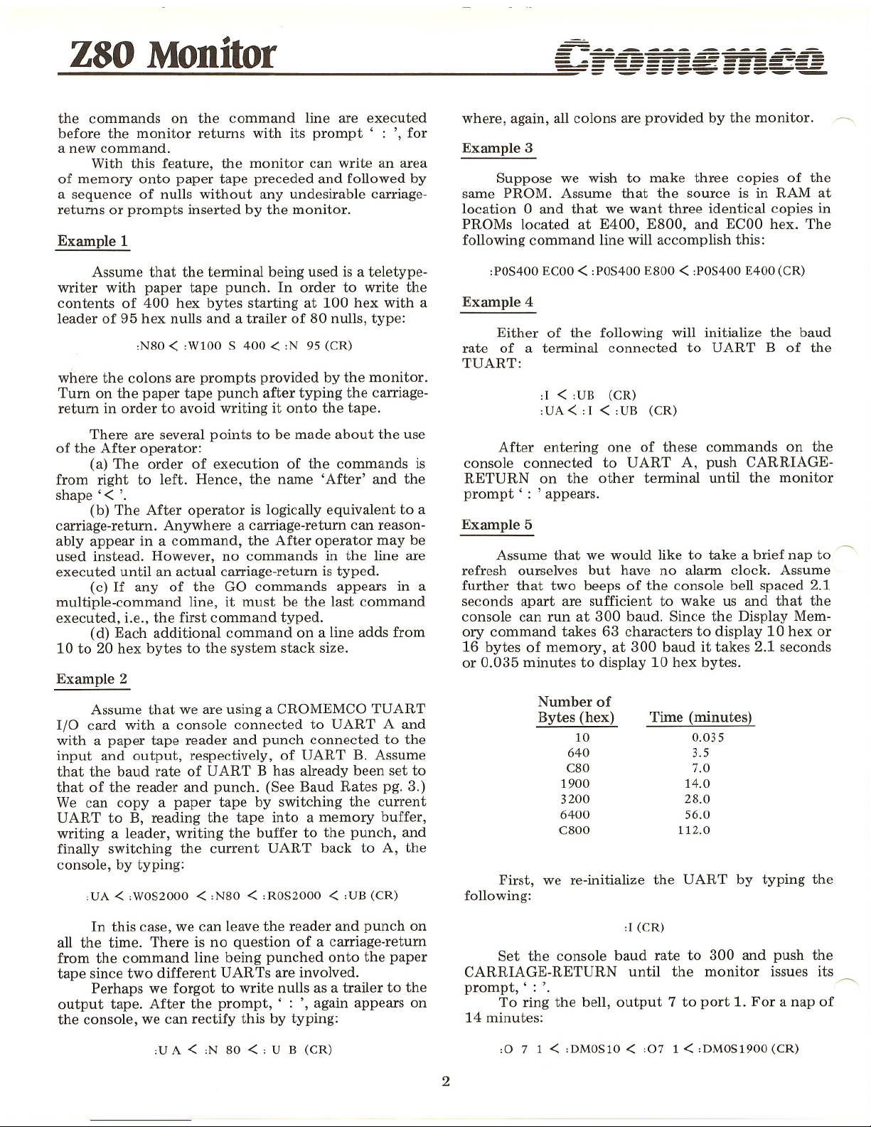
Table of Contents
Pg.No.
Introduction 1
Entry 1
System Stack 1
Command Format 1
Swath Operator 1
Multiple Commands: The After Operator 1
Example 1: Writing Paper Tapes
Example 2: Copying Paper Tapes
Example 3: Multiple Copies of PROMs
Example 4: Initializing UARTs
Example 5: A Timer
Errors and Escapes 3
Input and Output 3
Baud Rates and UART Selection 3
Interrupts 3
Loading the Monitor .4
Using the Monitor .4
COMMANDS 4
Display Memory, DM
Display Registers, DR
Go,G
Go with Breakpoints Set, G/
Initialize Baud Rate, I
Move, M
Nulls, N
Output, 0
Program PROMs, P
Read, R
Substitute Memory, 8M
Substitute Register
SA, SB, SC, SD, SE, SF, SH,
SI, SN, SP, SS, SX, SY,
SA', SB', SC', SD', SE', SF', SH'
UART Select, U
Verify, V
Write, W
Program Listing 7
Cross Reference 24
Page 5
Z80 Monitor
~ Introduction
The Z80 Monitor makes it possible to control
computers which use the CROMEMCO zputm from a
terminal keyboard. It includes executive commands to
examine and change memory, make a binary or an
ASCII dump of memory, move and compare blocks
of memory, output a byte of data to any port, read,
write, and punch nulls on binary paper tapes, program
2708 and 2704 PROMs using the CROMEMCO BYTE-
SAVER, and initialize and control both serial ports on
the CROMEMCOTUART.
Transfer of control to a program in memory can
be commanded from the keyboard with up to five
breakpoints set and with the initial contents of the
ZPU registers specified. When a breakpoint is en-
countered during execution, control is transferred
back to the monitor and the contents of all 22 ZPU
registers are stored. These register values can be exam-
ined and changed before execution of the program
is resumed.
Entry Points
The Z80 Monitor has three entry points. A
cold-start entry at EOOO hex selects bank 0 on
CROMEMCO memory boards and UART A on the
'-------"CROMEMCO TUART. It initializes the baud rate of
the UART to match that of the terminal being used. In
addition, it saves the contents of the Z80 registers I,
N (IFF), S (SP) , X (IX) , Y (IY) , A' , B' , C' , D' , E' ,
F' , and H' (HL') in the user-register area which is part
of the system stack. (If the Z80 stack pointer is point-
ing to RAM, then all registers except A and P (PC) will
be saved.) The contents of these registers are restored
when the monitor is exited by means of the GO
command.
The warm-start entry point at E008 hex is pro-
vided so that the monitor can be re-entered without
affecting the memory banks or the UART. The same
registers are saved as for the cold-start entry point.
The third entry point is used by the break-
point facility. Entry here saves the contents of all
registers. Memory banks and UART are unaffected.
System Stack
The monitor does not require the user to
address a RAM board at a special place in memory for
its stack and working storage area. (However, if the
breakpoint facility is used, there must be either RAM
at locations 30, 31, and 32 hex or PROM with the data
C3, 45, EO hex at those locations.) The monitor finds
the highest page of RAM active in the machine and
places its stack and temporary storage area there. At
least 60H or 96 bytes of this page must be reserved for
system use. If the multiple command facility is used,
1
-------- ---- --
- - ------ ---
= -- -===-=- ~=
- ----~ --.•.. ""-""" ~
each additional command in a command line requires
an additional 20 hex or 32 bytes stack room. (See
Multiple Commands.)
Command Format
The Z80 Monitor is controlled by one and two-
character commands from the terminal keyboard. The
format is free-form with respect to spaces.
In the following, DM is the Display Memory com-
mand and S is the Swath operator (see below). The
four examples are equivalent commands. They display
the contents of 100 hex bytes of memory beginning
with location 1000 hex. (' (CR) , indicates a carriage
return.)
DM1000 10FF (CR)
DM1000S100 (CR)
D M 1000 10FF (CR)
D M 1000 S 100 (CR)
When entering an address as a operand, only the
last four digits typed in are retained. For example,
'321000' is read as '1000'. Therefore, if a wrong digit
is entered, continue typing until the last four digits are
correct.
Only the last two digits typed are retained when a
two-digit number such as a data byte is entered.
Swatl. Operator
There are two ways to specify the address
range of many commands. The first is to simply list
the beginning and ending addresses (and, where
appropriate, the destination address). For example, the
first command below programs the range 0 through
13FF into PROMs starting at E400. The second com-
mand displays the contents of memory between
addresses E400 and E402.
PO 13F F E400
DME400 E402
Another way to do the same thing is to use the
Swath operator, S, to specify the width of the address
range rather than state the ending address explicitly.
PO S1400 E400
DM E400S3
Multiple Commands:
The After Operator
The After operator, , < " can be used to place
more than one command on a command line. All of
Page 6
Z80 M -~ --- --- - ----=--=-
ODIlOr 5.-= =-- === .: -=
-==.:::..::::.-.=..:.=.::..===.;::.::..:::._-------------
the commands on the command line are executed
before the monitor returns with its prompt' : " for
a new command.
With this feature, the monitor can write an area
of memory onto paper tape preceded and followed by
a sequence of nulls without any undesirable carriage-
returns or prompts inserted by the monitor.
Example 1
where, again, all colons are provided by the monitor. ~
Example 3
Suppose we wish to make three copies of the
same PROM. Assume that the source is in RAM at
location 0 and that we want three identical copies in
PROMs located at E400, E800, and ECOOhex. The
following command line will accomplish this:
Example 4
:POS400 ECOO<:POS400 E800 <:POS400 E400 (CR)
First, we re-initialize the UART by typing the
following:
:1 < :VB (CR)
:VA<:I < :VB (CR)
Time (minutes)
0.035
3.5
7.0
14.0
28.0
56.0
112.0
Number of
Bytes (hex)
10
640
C80
1900
3200
6400
C800
After entering one of these commands on the
console connected to UART A, push CARRIAGE-
RETURN on the other terminal until the monitor
prompt' : ' appears.
Either of the following will initialize the baud
rate of a terminal connected to UART B of the
TUART:
Example 5
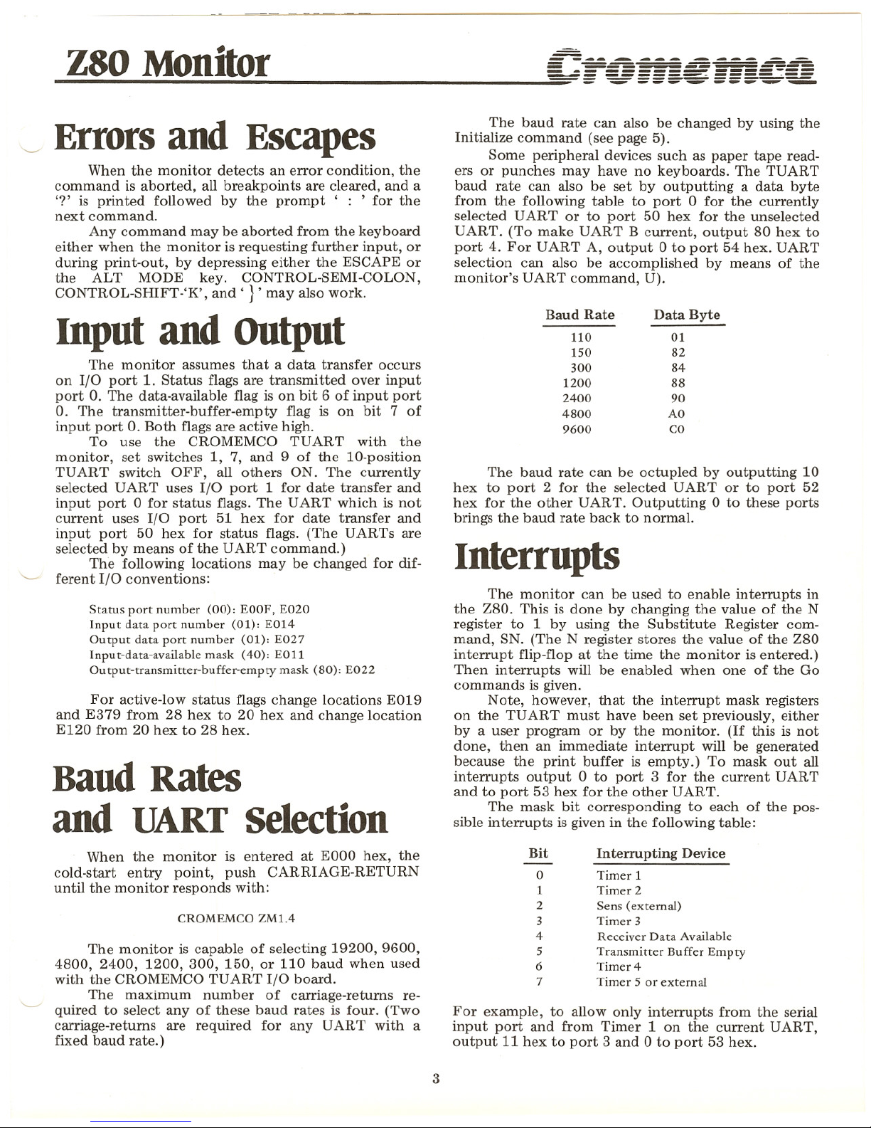
Assume that we would like to take a brief nap to ~
refresh ourselves but have no alarm clock. Assume
further that two beeps of the console bell spaced 2.1
seconds apart are sufficient to wake us and that the
console can run at 300 baud. Since the Display Mem-
ory command takes 63 characters to display 10 hex or
16 bytes of memory, at 300 baud it takes 2.1 seconds
or 0.035 minutes to display 10 hex bytes.
Example 2
Assume that we are using a CROMEMCO TUART
I/O card with a console connected to UART A and
with a paper tape reader and punch connected to the
input and output, respectively, of UART B. Assume
that the baud rate of UART B has already been set to
that of the reader and punch. (See Baud Rates pg. 3.)
We can copy a paper tape by switching the current
UART to B, reading the tape into a memory buffer,
writing a leader, writing the buffer to the punch, and
finally switching the current UART back to A, the
console, by typing:
Assume that the terminal being used is a teletype-
writer with paper tape punch. In order to write the
contents of 400 hex bytes starting at 100 hex with a
leader of 95 hex nulls and a trailer of 80 nulls, type:
:N80 < :W100 S 400 <:N 95 (CR)
:VA < :WOS2000 < :N80 < :ROS2000 < :VB (CR)
where the colons are prompts provided by the monitor.
Turn on the paper tape punch after typing the carriage-
return in order to avoid writing it onto the tape.
There are several points to be made about the use
of the After operator:
(a) The order of execution of the commands is
from right to left. Hence, the name 'After' and the
shape'
< '.
(b) The After operator is logically equivalent to a
carriage-return. Anywhere a carriage-return can reason-
ably appear in a command, the After operator may be
used instead. However, no commands in the line are
executed until an actual carriage-return is typed.
(c) If any of the GO commands appears in a
multiple-command line, it must be the last command
executed, i.e., the first command typed.
(d) Each additional command on a line adds from
10 to 20 hex bytes to the system stack size.
In this case, we can leave the reader and punch on
all the time. There is no question of a carriage-return
from the command line being punched onto the paper
tape since two different UARTs are involved.
Perhaps we forgot to write nulls as a trailer to the
output tape. After the prompt, , : " again appears on
the console, we can rectify this by typing:
:1(CR)
Set the console baud rate to 300 and push the
CARRIAGE-RETURN until the monitor issues its
prompt,': '. ~
To ring the bell, output 7 to port 1. For a nap of
14 minutes:
:V A < :N 80 < : V B (CR)
:0 7 1 < :DMOS10 < :07 1 < :DMOS1900 (CR)
2
Page 7
Z80 M -., --------- ----~-=-
onIlor = -_ -=--==;;=== _~~
-=:=.;:;...;:;;......=.:.=-=~~.;;;;.,;,~--------------
Errors and Escapes
When the monitor detects an error condition, the
command is aborted, all breakpoints are cleared, and a
'?' is printed followed by the prompt ' : ' for the
next command.
Any command may be aborted from the keyboard
either when the monitor is requesting further input, or
during print-out, by depressing either the ESCAPE or
the ALT MODE key. CONTROL-SEMI-COLON,
CONTROL-SHIFT-'K', and' }' may also work.
The baud rate can also be changed by using the
Initialize command (see page 5).
Some peripheral devices such as paper tape read-
ers or punches may have no keyboards. The TUART
baud rate can also be set by outputting a data byte
from the following table to port 0 for the currently
selected UART or to port 50 hex for the unselected
UART. (To make UART B current, output 80 hex to
port 4. For UART A, output 0 to port 54 hex. UART
selection can also be accomplished by means of the
monitor's UART command, U).
Interrupts
The baud rate can be octupled by outputting 10
hex to port 2 for the selected UART or to port 52
hex for the other UART. Outputting 0 to these ports
brings the baud rate back to normal.
The monitor can be used to enable interrupts in
the Z80. This is done by changing the value of the N
register to 1 by using the Substitute Register com-
mand, SN. (The N register stores the value of the Z80
interrupt flip-flop at the time the monitor is entered.)
Then interrupts will be enabled when one of the Go
commands is given.
Note, however, that the interrupt mask registers
on the TUART must have been set previously, either
by a user program or by the monitor. (If this is not
done, then an immediate interrupt will be generated
because the print buffer is empty.) To mask out all
interrupts output 0 to port 3 for the current UART
and to port 53 hex for the other UART.
The mask bit corresponding to each of the pos-
sible interrupts is given in the following table:
Input and output
The monitor assumes that a data transfer occurs
on I/O port 1. Status flags are transmitted over input
port O. The data-available flag is on bit 6 of input port
O. The transmitter-buffer-empty flag is on bit 7 of
input port O.Both flags are active high.
To use the CROMEMCO TUART with the
monitor, set switches 1, 7, and 9 of the 10-position
TUART switch OFF, all others ON. The currently
selected UART uses I/O port 1 for date transfer and
input port 0 for status flags. The UART which is not
current uses I/O port 51 hex for date transfer and
input port 50 hex for status flags. (The UARTs are
selected by means of the UART command.)
The following locations may be changed for dif-
ferent I/O conventions:
Status port number (00): EOOF, E020
Input data port number (01): E014
Output data port number (01): E027
Input-data-available mask (40): E011
Output-transmitter-buffer-empty mask (80): E022
For active-low status flags change locations E019
and E379 from 28 hex to 20 hex and change location
E120 from 20 hex to 28 hex.
Baud Rates
and UART selection
Baud Rate
110
150
300
1200
2400
4800
9600
Data Byte
01
82
84
88
90
AO
CO
When the monitor is entered at EOOOhex, the
cold-start entry point, push CARRIAGE-RETURN
until the monitor responds with:
CROMEMCO ZM1.4
The monitor is capable of selecting 19200, 9600,
4800, 2400, 1200, 300, 150, or 110 baud when used
with the CROMEMCO TUART I/O board.
The maximum number of carriage-returns re-
quired to select any of these baud rates is four. (Two
carriage-returns are required for any UART with a
fixed baud rate.)
3
Bit Interrupting Device
o Timer 1
1 Timer 2
2 Sens (external)
3 Timer 3
4 Receiver Data Available
5 Transmitter Buffer Empty
6 Timer 4
7 Timer 5 or external
For example, to allow only interrupts from the serial
input port and from Timer 1 on the current UART,
output 11 hex to port 3 and 0 to port 53 hex.
Page 8
Z80M -. --------------=
-=.:~..::.:.::.o::..:;n~I;;;;.;:;..lo..;;..;:r~ =_- ' ....::_
Loading the Monitor
The paper tape can be loaded into RAM and
thence into PROM as follows.
Temporarily address a RAM card at EOOO hex.
Address the BYTESA VER card at some other address,
say AOOOhex. Place an erased 2708 in PROM position 1
(A400 hex).
Enter the following loader program via the front
panel switches at any convenient address. Since' it
only contains relative jumps, it will execute anywhere
in memory without change. The places that may need
to be altered for different I/O conventions are under,
lined.
CARRIAGE-RETURN twice. The monitor will then ~
respond:
CROMEMCO ZM1.4
followed by a prompt' : '. The monitor is then ready
to accept commands from the keyboard.
COMMANDS
DISPLA Y MEMORY
[1] DM beginning-addr ending-addr (CR)
P EOOO S 400 A400 (CR)
Align the first byte of data on the paper tape over
the read sensors of the paper tape reader. Begin execu-
tion of the loader program and then turn on the reader.
After the tape is read, stop the reader.
If necessary, change the monitor locations indi-
cated above to fit your I/O conventions.
Execute the monitor starting at location EOOO
hex. Depress carriage return several times to set the
baud rate to suit your terminaL The monitor will now
program itself into the PROM at A400. Turn on the
BYTESA VER program power switch and enter the
following command:
21 00 EO
DB 00
E6 40
28 FA
DB 01
77
23
18 F4
LD HL, OEOOOH
LOOP: IN A, (STATUS)
AND DAV
JR Z, LOOP
IN A, (DATA)
LD (HL), A
INC HL
JR LOOP
or
DM beginning-addr S swath-width (CR)
The contents of memory are displayed in hexa-
decimal form. Each line of the display is preceded by
the address of its first byte. Example:
:DMI00 S3
0100: C3 34 7F
DISPLAY REGISTERS
[2] DR (CR) ~
When the monitor is re-entered from a breakpoint,
the contents of all the Z80 registers are stored in an
area called the user-register area. (When the monitor is
entered via reset or the warm-start entry point, all
registers except A, B, C, D, E, F, HL, and P are saved
in the user-register area. However, if the stack pointer
is pointing to RAM, then all but A and P will be saved.)
DR causes these stored registers to be displayed
in the following format:
If the PROM programs correctly, the monitor will
respond with a line feed and the prompt' : '. Turn off
the program power switch and the computer power
switch. Re-address the BYTESA VER to EOOO and
move the monitor PROM to PROM location O. Change
the RAM address to something other than EOOO. You
are then ready to use the monitor in PROM.
using the Monitor
Set the power-on jump switch on the Cromemco
ZPU card to E (1110 binary). Whenever the computer is
reset, control will then immediately pass to the monitor.
If the ZPU is used with the Cromemco TUART
I/O card, depress CARRIAGE-RETURN two to four
times. This will set the UART on the serial interface
card to the baud rate of the terminal being used.
When used with a serial interface card with baud
rate fixed to that of the terminal, simply depress
4
A=OI B=12 C=34 D=56 E=78 F=9A HL=BCDE
I=FO N=OO P= 1234 S=5678 X=9ABC Y=DEFO
A'23 B'45 C'67 D'89 E'AB F'CD HL'EFOI
If interrupts were enabled when the monitor was
entered, then N=1. Otherwise, N=O.
The flag registers, F and F', are packed as follows:
S,Z,x,H x,P/V,N,C
i.e., sign, zero, (unknown), half-carry, (unknown),
parity or overflow, subtraction, and carry flags.
GO
[3] G (CR) ~
The Z80 registers are loaded with the values saved
in the user-register area. (These are the values displayed
with the DR command.) Execution then resumes at
Page 9
Z80 M _I -------------=--=--
OnIor == -=-===:=::~====-::==
'=='= ~ =:s--=- :::: ~~-=-
-==.;:~~.;;;.;",;;;;.;:~;;;....;....;;,---------------
the location contained in the user-pro gram-counter, P.
~ .
[4] G startmg-addr (CR)
This command is exactly like [3] except that the
user-program-counter, P, is first loaded with starting-
address. Thus, execution begins at starting-address.
GO WITH BREAKPOINTS SET
[5] G / breakpoint-addr-1 breakpoint-addr-2 ... (CR)
[6] G starting-addr / brkpt-addr-1 brkpt-addr-2 ... (CR)
Commands [5] and ] 6] are like [3] and [4],
respectively, except that breakpoints are set at
breakpoint-address-1, breakpoint-address-2, etc.
When a breakpoint is encountered in the execu-
tion of the user program, the monitor is re-entered. All
registers are saved in the user register area (which is
part of the system stack), the address of the breakpoint
is printed, and all breakpoints are cleared (i.e., the user
program is restored to its original state). Finally, the
prompt, , : ' is issued for the next command from the
keyboard. Note the following about the use of break-
points:
(a) Breakpoints can only be set in programs resid-
ing in RAM. This is because the monitor inserts a RST
48 instruction (F7 hex) at each breakpoint location.
(The original contents of these locations are saved so
that they can later be restored.)
(b) Up to five breakpoints can be set. If an
attempt is made to set a sixth breakpoint, the monitor
will print a question mark to indicate error, erase all
breakpoints, and prompt for a new command.
(c) When a breakpoint is set, the monitor inserts
a 3-byte jump instruction at location 30 hex. This
means that locations 30, 31, and 32 hex are not avail-
able to the user program when breakpoints are used.
(d) The monitor temporarily uses ten bytes on
the user's stack in executing a breakpoint. The area
reserved for the user's stack must, therefore, be at least
ten bytes larger than that required for the user's
program.
(e) If breakpoints are set in a program and the
computer is reset and the monitor re-entered before
any breakpoint is reached in the execution of the pro-
gram, then the breakpoints will have to be removed
from the program by means of the Substitute Memory
command, SM. However, if any breakpoint is reached,
all breakpoints are automatically cleared by the
monitor.
INITIALIZE BAUD RATE
[7] I (CR)
After the CARRIAGE-RETURN is typed, change
the baud rate of the terminal to the desired value and
then push the CARRIAGE-RETURN until the monitor
responds with its prompt, , : '.
5
The monitor is capable of selecting 19200, 9600,
4800, 2400, 1200, 300, 150, or 110 baud when used
with the Cromemco TUART I/O board. The maximum
number of carriage-returns required to select any of
these baud rates is four.
The command is particularly useful for setting
the baud rate of the second serial port on the TUART.
(See Multiple Commands.)
MOVE
[8] M source-addr source-end destination-addr (CR)
or
M source-addr S swath-widthdestination-addr (CR)
Move the contents of memory beginning with
source-address and ending with source-end to destina-
tion-address. After the move, the monitor verifies that
source and destination are the same. This will result in
a print-out of discrepancies which are not really errors
after certain types of overlapping moves. However, this
print-out can be terminated by depressing ESCAPE
or ALT MODE.
The Move command can be used to fill a block of
memory with a constant. For example, to enter zeros
between locations 100 and 108, use the Substitute
Memory command to enter 0 at location 100, and then
move 100 through 107 to 101:
M100 107 101
or
M 100 S 8 101
Care should be taken not to overwrite the system
stack which resides in the top of active RAM. (See
System Stack.)
NULLS
[9] N hex-number (CR)
Write hex-number nulls to the current device.
This command is used to punch leaders and trailers on
paper tape. (See Multiple Commands.)
OUTPUT
[10]
0 data-byte port-number (CR)
Outputs data to a port. One use of this command
is to select banks on Cromemco memory boards.
When the monitor is first entered on power-up or reset,
it selects bank 0 and turns off all other memory banks.
Either a software output or a monitor output to
port 40 hex serves to change the bank selection. To
select bank n, output a byte with bit n high. To select
two banks, nand m, output a byte with both bits n
and m high.
Page 10
Z80 M _I ------------~~
Onl or == --=======~====:'==
~ = -=.:- =~S"-=- ==::-~~
....:;=-.;;...;;......:;;"";,,,;;~...;;;;;;.;;;;.;......;;;..~----------------
Bank
o
1
2
3
4
5
6
7
Output byte
01
02
04
08
10
20
40
80
Read binary or ASCII input from paper tape
reader or console and store in memory from destination-
address through destination-end. After destination-end
has been filled, the monitor prompts for the next
command.
SUBSTITUTE MEMORY
[13] SM address (CR)
For example, the first command selects bank 5 and the
second selects banks 4 and 5.
o
20 40
o 30 40
PROGRAM
[11] P source-addr source-end destination-addr (CR)
or
P source-addr S swath-widthdestination-addr (CR)
Program from source-address through source-end
into PROMS beginning at destination-address.
If the length of the source is not a multiple of
400H (1024 decimal) or if the destination does not
begin at 400H boundary, the monitor will reject the
command. (Multiples of 400H end in '000', '400',
'800', or
'COO'.)
Any number of 2708 or 2704 PROMS can be
programmed in the execution of one command as long
as there are enough BYTESAVERS to contain them.
Each PROM is verified with its source after all are pro-
grammed and any discrepancies are printed out. If
there are none, the prompt ' ; , is issued and the
monitor awaits the next command.
Software can be loaded into a PROM in as small
increments as you desire provided it is added to pre-
viously unused areas of the PROM.
This is done by first using the Move command,
M, to transfer the current contents of the PROM down
to RAM, adding the new software to an area of RAM
which corresponds to the unused portion of the PROM
and finally using the Program command, P, to re-
program the PROM with the result.
Although the entire PROM must always be pro-
grammed, it never hurts to re-write the same data
over again.
In general, a 1 may be written over a 1, a 0 over
either a 1 or a 0, but the only way to change O'sto l's
is to erase the PROM with appropriate UV light. (See
the BYTESAVER manual for details.)
READ
[12] R destination-addr destination-end (CR)
or
R destination-addr S swath-width (CR)
6
Substitute Memory desplays the contents of
address and outputs a dot,' . ',as a prompt for the
substituted value. If no change is desired, type a
space or another dot. Otherwise, enter the new value.
The monitor accepts hex digits until it gets a delimiter,
such as a space, dot, or carriage-return retaining the
last two digits entered as the value. Unless the delimiter
is a carriage-return, the monitor outputs the contents
of the next sequential memory location with a dot
prompt. A carriage-return terminates the command.
SUBSTITUTE REGISTER
[14] S register-name (CR)
Register-name may be A, B, C, D, E, F, H (HL), I,
N (state of the Z80 interrupt flip-flop), P (PC), S (SP),
A', B',
C', D', E', F', H' (HL'), X (IX), or Y (IY).
This command prints the name of the user-register
requested, displays its contents, outputs a dot,' . ',as
a prompt for the substituted value. If no change is
desired, type a space or another dot. Otherwise, enter
the new value. The monitor accepts hex digits until it
gets a delimiter such as space, dot, or carriage-return
retaining the last two digits (four digits for a 2-byte
register). Unless the delimiter is a carriage-return, the
monitor prints the name and contents of the next
register followed by the dot prompt. A carriage return
terminates the command.
UART SELECT
[15] U device-name (CR)
Device-name may be A or B. The Cromemco
TUART has two UARTs. When the monitor is entered
via reset, UART A is selected for its input/output
channel. This command allows the user to change the
UART selection. It is often used in the multiple com-
mand mode (see page 2).
VERIFY
[16] V source-addr source-end destination-addr (CR)
or
V source-addr S swath-width destination-addr (CR)
Page 11

Z80 Moni~or == :::-_-:.~-~~ ~-=
.1.1 == ~==S-~===-~~
-===~""::;':'==-===~~------- ..iiiiiiiiO"
Verify that the block of memory between source-
address and source-end contains the same values as the
block beginning at destination-address. The addresses
and contents are printed for each discrepancy found
(unless the print-out is terminated by ESCAPE or ALT
MODE).
This command works by reading bytes from the
source and destination and comparing them. If a dis-
crepancy is found, the memory is read again for print-
out. Thus, it can happen that a discrepancy is printed-
out with the source and destination contents indicated
to be the same. This is caused by a defective memory
element.
WRITE
[17] Wsource-addr source-end (CR)
or
W source-addr S swath-width (CR)
Write binary or ASCII output from source-address
through source-end to the current device (selected by
the DART command). After source-end has been
written, the monitor prompts for the next command.
The Write command is useful for punching binary
or ASCII paper tapes of the contents of memory
and for looking at the ASCII contents of memory on
the console.
When punching a paper tape, it isusually desirable
to punch series of nulls as leader and trailer. This can
best be done in conjunction with the Null command
and the After operator. (See Multiple Commands for
examples of this usage.)
Program Listing
GET CHARACTER FROM INPUT.
CHECK INPUT
& RETURN WITH DATA IF READY,
WARM START ENTRY. INITIALIZES THE BREAKPOINT
STORAGE POINTER. SAVES ALL REGISTERS EXCEPT
THE PROGRAM COUNTER, BUT DOES NOT DISPLAY THEM.
ENTER THE MONITOR FROM RESET.
COLD START ENTRY. INITIALIZES THE UART
AND ZEROES THE BREAKPOINT STACK POINTER.
ALTERS THE A-REGISTER. SAVES ALL OTHER
REGISTERS EXCEPT THE PROGRAM COUNTER,
BUT DOES NOT DISPLAY THEM.
iSELECT BANK 0
iSIMULATE UPC
i USER-F·-REGISTER
;SIMULATE UPC
;UAF
;FLAG:
iWARM-START ENTRY
A,STAT
DAV
Z
A.DATA
AF
AF
A,80H
COMMON
A, 1
40H,A
AF
AF
COMMON
IN
AND
RET
IN
RET
WSTART: PUSH
PUSH
LD
JR
CSTART: LD
OUT
PUSH
PUSH
JR
CHK IN:
0054
0055
0056
0057
0058
0059
0060
0061
0062
0063
0064
0065
0066
0067
0068
0069
0070
0071
0072
0073
0074
0075
0076
0077
0078
0079
0080
0081
0082
0083
0084
0085
0086
0087
0088
0089
f·OOO ~-IEOl
f:OO~)
1)340
t- 0011 1--5
f·
oo~, f- 5
!:00,';J 842
[-()O[: HBOO
t:OJ0 }'640
[,OJ~) C8
[-(11 ~i DBOl
[-OJ~, (:9
['GOB 1'5
[-OO~,.
r-. 5
[.001\ ~~E80
[:00(: 183C
1
Page 12

Z80 Monitor
----.....-...--- ---- --
-----~===---------.._---- --:--.--
----------~
WITH THE 3P+S: 2400, 300, 110.
INITIALIZE BAUD RATE OF THE CURRENT DEVICE.
BREAKPOINT ENTRY. INITIALIZES NOTHING.
SAVES ALL REGISTERS AND DISPLAYS THEM.
TWO CARRIAGE-RETURNS ARE REGUIRED FOR
ANY UART WI1H A FIXED BAUD RATE.
i ADJUST BRKPT
i SLOW THE CLOCK
iOCTUPLE THE CLOCK
i& RESET CURRENT DEVICE
iSELECT DEVICE A
iRESET DEVICE B
i [CONTINUE BELOW]
( SP ) , HL
BPARLP, A
BCMNDP,A
AF
A,STAT
TBE
Z,PBY1
AF
DATA,A
CHf.<.IN
Z,GBYTE
7FH
HL, BAUDRS
C, AB AlJDP
A, 11H
ACMNDP, A
GBYTE
GBYTE
CR
A, 1
NZ,IT1
OUT
OUT
EX
INIT:
PRINT CHARACTER.
INITBAUD: LD
LD
LD
ITl: OUT
OUTI
CALL
CALL
CP
LD
.JR
RET
PUSH CARRIAGE-RETURN TO SELECT THE PROPER BAUD
RATE FOR THE CURRENT TERMINAL. (THE MAXIMUM
NUMBER OF CARRIAGE-RETURNS REGUIRED IS FOUR. )
SELECT DEVICE A
& INITIALIZE ITS BAUD RATE.
ENTER WITH A= 1.
WITHE THE CROMEMCO TUART ANY OF ~HE FOLLOWING
BAUD RATES CAN BE SELECTED:
19200, 9600, 4800, 2400, 1200, 300, 150, 110.
GBYTE: CALL
JR
AND
RET
PBYTE: PUSH
PBY1: IN
AND
JR
POP
OUT
RET
SVMS:
0090
0091
0092
0093
0094
0095
0096
0097
0098
0099
0100
0101
0102
0103
0104
0105
0106
0107
0108
0109
0110
0111
0112
0113
0114
0115
0116
0117
0118
0119
0120
0121
0122
0123
0124
0125
0126
0127
0128
0129
0130
0131
0132
0133
0134
0135
0136
0137
0138
0139
0140
0141
0142
0143
0144
0145
0146E04:J [-3
I· 0 J {. CDOEEO
rOJ 'I ;'8FB
FOJH f'67F
f-OJD (:9
[-OJ [- :·5
HsJ f- I>BOO
t~0;' 1 [.680
[-o;<{ ;'8FA
LO;'~,
f- 1
f· O;'h »301
FO;'(-I (:'1'
F02CI D354
EO;?B D352
E02D 21A3E3
E030 OEOO
F032 3E11
E034 V302
E036 EDA3
E038 CD16EO
E03B CD16EO
E03E rEOD
F040 3E01
[042 20FO
r04~ (:9
8
Page 13

Z80 Monitor
-------- ---- --
- ---------- -------- ---
- -- ~=====:=--
- ----~---~~
PLACE SYS STAC~ AT HIGHEST PAGE OF
AVAILABLE RAM.
ALLOW ROOM FOR TEMP STORAGE.
INC DE
EX DE, HL
LD SP,HL
EX DE, HL
LD BC,DUPC-DUHL+3
ADD HL,BC
PUSH HL
PUSH IX
PUSH IY
EX DE,HL
ADD HL BC
LD C,L
DEC HL
PUSH HL
POP IX
CP 1
JR C,COM3
LD (HL ),C
INC HL
LD (HL),O ;BP-STAC~ ENDMAR~
INITIALIZE THE TUART IF ENTRY WAS VIA RESET.
(A CONTAINS 1.)
HL,OOFFH-TEMPS
H
AI < HL )
(HL)
(HL) ;DID IT CHANGE?
Z,COM1
(HL) iYES. RESTORE IT.
CALL Z,INIT
USER SP
i UBC
i ENTRY FL.AG
i UDE
i UHL.
i -; UPC, HI BYTE
iRET ADDR
i-; UHL,LO ON SYS ST~
i UAF
i FLAG:
iBREA~POINT ENTRYi
i SAVE
iENTRY FLAG
i ENTRY?
i SKIP IF VIA BP.
iBP PNTR, LO BYTE
;CURRENT SYS SP
i HL =
;USP
; UIX
;UIY
HL
(SP ) , HL
AF
A
BC
B/A
DE
HL.
A, I
H,A
A,B
DE,HL
HL/9
HL/SP
BC, 10
DEC
EX
PUSH
SUB
~D
EX
LD
ADD
LD
LDDR
LD
DEC
LD
INC
CP
JR
DEC
LD
LD
COM1:
COMMON: PUSH
LD
PUSH
PUSH
COM3:
0147
0148
0149
0150
0151
0152
0153
0154
0155
0156
0157
0158
0159
0160
0161
0162
0163
0164
0165
0166
0167
0168
0169
0170
0171
0172
0173
0174
0175
0176
0177
0178
0179
0180
0181
0182
0183
0184
0185
0186
0187
0188
0189
0190
0191
0192
0193
0194
0195
0196
0197
0198
0199
0200
0201
0202
0203
0204
l7046 ~)B
EO.!!7[~3
FOlt8 F 5
f049 (17
F04£ ~?lE900
£:051 25
E052 7E
E05~:J 34
E054 BE
£::055
28FA
E057 35
FOltA C5
£04B 47
F04C H5
F04JJ F5
EO~ 78
E059 EB
E051\210900
E05D 39
E05E 010AOO
E061 EDB8
£092 ED57
E084 67
F07f- CC29EO
E063 13
EOb4 FB
EOb5 F9
EOb6 EB
E067 010aoo
F061\ 09
£068 E5
EObC DDE5
E06E FDE5
EO"lO FB
EO'll 09
E07~! 4D
EO-/3 2B
F074 1:5
F07~~ HDEI
E077 FEOI
E07(t3807
E07B 71
E07C ;'3
E07D ~~600
9
Page 14

Z80 Monitor
=:: -~ - --- - --- ~~
- -- --====-=-=--
- ----~----~
GET 1-BYTE COMMAND.
RETURNS VALUE IN HL
& JUMPS TO THAT ADDR.
iCLEAR AL.L BREAKPOINTS
CALL
CMND: LD
PUSH
CMND1: L.D
CALL
CL1:
i ADJUST BPSP
iRE-ENTRY POINT
iFOR RECURSION
iSET-UP RETURN
i UBC (
i UDE'
i UHL (
i UAF'
iRESTORE MEM CONTENTS
iFOR THE BENEFIT
iOF ERROR & ESCPE
iRE-INITIALIZE SP
i UIN
iBP-ERASED MARK
;BP STI-<.EMPTY?
iIF BPMRK, BP IS SET
iPOINTS TO BPSP,LO
iBPSP NOW IN HL
CRLF
DE,CMND
DE
HL.,PRMPT
PMSG
A, (HL)
BPMRI-<.
NZ,CL2
A,L
HL. '
( HL ) , A
CL.l
DE,-LENRGS
HL,DE
SP,HL.
ENTRY WAS VIA A BREAKPOINT
HL, HEAD
NC,PMSG
BC, [['P'+CASEJ SHL 8J+86H
i IF BP ENTRY,
C,SUBR3 iDISPLAY THE PC.
IX
HL
L, (HU
BC
DE
HL
L,O
PO,COM4
L.
HL
AF,AF'
AF
AF,AF'
(HL)
HL
D, (HL)
HL
E, (HL.)
HL.
L.D
DEC
L.D
LD
ADD
LD
INC
DEC
LD
DEC
LD
DEC
LDD
JR
LD
CP
,JR
IS SET,
LD
CALL
LD
CALL
PUSH
POP
LD
LD
JP
INC
PUSH
EX
PUSH
EX
EXX
PUSH
PUSH
PUSH
EXX
CLBP:
0205
0206
0207
0208 COM4:
0209
0210
0211
0212
0213
0214
0215
0216
0217
0218
i IF CY
0219
0220
0221
0222
0223
0224
0225
0226
0227
0228
0229
0230
0231
0232
0233
0234
0235
0236
0237
0238
0239
0240
0241
0242
0243
0244
0245
0246
0247
0248
0249
0250
0251
0252
0253
0254
0255
0256
0257
0258
0259
0260
0261
FOR6 l1E6FF
FOI:JC~ 19
[:OB£\ F 9
f-OAII 'IE
FO~,~1 I; EOB
f- OA"I ~?OOA
FORB CD4DE1
FORE J1BEEO
[OC1 D5
t:OC~' ~J 1AEE3
EOC5 CDOFE2
EOB::I "/D
EOB4 2B
EOB~, 77
{-OAO DDE5
f:Ol\;-!F 1
t~
OA3 bE
I'ONI ~{4
f OAf'. ~m
EOf'.8 ~6
EOAC ;2'B
EOf',D 5E
EOAE ;?B
f~OAF FDA8
f:- OR 1 18F 1
F094 21FOE3
E097 D40FE2
E09A 018650
EO?D DC23E3
EOB5 2EOO
FOB7 F28BEO
FOBA ~}C
FORB E5
Foac 08
F08n [-5
E08E 08
EOSE D9
F090 C5
F091 H5
FO<:;';.' F 5
E09~i D9
10
Page 15

Z80 Monitor
-------- ---- --
- ----------- ------ ---
- ------------
=-== =====~==:t=..:=.=
- ---- ~ -~~-.-... ~
HL NOW PNTS TO THE COMMAND TABLE.
GET THE COMMAND.
DE GETS THE FIRST ALPHA CHAR LESS 'D'.
ERROR
& ESCAPE. RETURNS TO CMND WITH SP
POINTING TO SAVED-REG AREA (UHL').
PROGRAM PROMS. ABORTS IF DESTINATION
IS NOT ON A 1K (400H) BOUNDARY, OR IF SWATH
WIDTH IS NOT A MULTIPLE OF 110<..
i MOVE IT
i ITERATION CT
i TIMES 2
i + TBL ADDR
.( 'D'?
.,' 'W'?
i INITIALIZE FOR SUBR
i SOURCE
;# OF ITERATIONS
i ARE INCREMENT ~oo(
iDESTINATION BOTH
i MUL TIPLES OF
; l024?
iCLEAR ANY BRKPTS
;ERROR VECTOR
;NEXT CMND GHAR
i (USED IN SUBST & DISPL)
iGET NON-SPACE
;IF CR, IGNORE.
HL
HL,320
( SP ) , HL
MVE
( SP ) , HL
HL
A,H
L
NZ,PRl
L3NCR
A,B
D
3
C
E
NZ,ERROR
A, '?'
PCHR
CLBP
SKSGO
Z
'D'+CASE
C,ERROR
'W'-'D'+1
NC,ERROR
E,A
D,O
C,D
DE,HL
HL,HL
HL. DE
E, (HL)
HL
D, (HL)
DE,HL
SKSGO
'M'+CASE
(HL)
LD
tX
ADD
ADD
LD
INC
LD
EX
CALL
CP
JP
CALL
RET
SUB
JR
CP
JR
LD
LD
PUSH
LD
PR 1.: EX
CAL.L
EX
DEC
LD
OR
JR
ERROR: LD
CALL
ESCPE: JR
PROG: CALL
LD
OR
AND
OR
OR
ERRV1: JR
0262
0263
0264
0265
0266
0267
0268
0269
0270
0271
0272
0273
0274
0275
0276
0277
0278
0279
0280
0281
0282
0283
0284
0285
0286
0287
0288
0289
0290
0291
0292
0293
0294
0295
0296
0297
0298
0299
0300
0301
0302
0303
0304
0305
0306
0307
0308
0309
0310
0311
0312
0313
0314
0315
0316
0317
0318
FOC8 CDDDE1
EOCB C8
EOCC D644
EOCE 3815
EODO FE14
EOD2 ~-JO11
FOD4 5F
EOD~~ 1600
EOE5 3E3F
FOE7 CD12E1
FOEA 18B4
[OEC CDA5El
FOEF 78
EOFO B2
EOFl E603
EOF~~ B 1
FOF4 B3
[-OF5 ~~OEE
FOF"! F5
EOF8 ;)14001
EOFB E3
EOFC CD1AE2
FOf-F f::3
E100 2B
U01 7C
E 10;'> B5
E103 20F6
FOln 'IA
EODS EB
EOD9 29
EODA 19
EODB 5E
EOOC 23
EODD 56
EODE EB
EODF CDDDE1
-EOF2 FE4D
FOE4 E9
11
Page 16

Z80 M -~ -------- -----=--=-
OllIlOr - - -:.._= === ...:_
-==.:::;..;:~..=.;..=.::...:;;;,;;;;:.;;;;;;..;:,,;;;;~--------------
r: 1O~I E 1
0319
POP
HL
0320JR
I.,IRFY
i VER IFY IT
03220323 i
PRINT THE 2 BYTES IN (HL) &
(HL -1 ).
DECREMENTS HL BY 2.AL TERS A.
PRESERVES OTHER REGS.
0327 P2NMS:CALL
PNM
0328
DEC
HL
0329CAL.L
PNM
0330DEC
HL
i (CONTINUE BELOW)
0332
0333 i
PRINT SPACE.
ALTERS A.
0335 SPACE:LD
A,20H
i (CONTINUE BELOW)
03370338 i
PRINT THE CHARACTER
IN THE A-REGISTER.
(CHKS INPUT FOR ESC. ) PRESERVES ALL REGS.
0341 PCHR:
PUSH
AF i SAVE THE CHAR
0342 PC1:AND7FH
0343
CPEse
0344
JR
Z,ESCPE
0345
CPALT iALT MODE?
0346JR
Z,ESCPE
~\
0347CALLCHKIN
0348
JR
NZ,PCl
0350 PC2:
POP
AF
0351
PUSH
HL.
0352
PUSH
AF
0353AND
7FH
0354
CALL
PBYTE
0355
L.D
HL.,LFNN
0356CPCR
0357
CALL
Z,PMSG
0358
CP1.-.:: I iRECURSIVE CALL
0359
JRNZ,PC3 i ON CMND'-;:O
0360POPAF
0361LDA,CR i YES.
CONVERT
0362
PUSHAF
i '<.' TO A CR.
0363
PUSHDE
0364
PUSHBC
0365CALLCMNDl
0366POPBC
0367POP
DE
0368 PC3:POPAF
0369
POP
HL
0370
RET
0373 i
GET CHARACTER.
RETURNS IT IN A.
ALTERS F.
0376 GCHR:CALLGBYTE
12
Page 17

Z80 M -, ----- --------=-=-OnI or = --===:=~~====-::==
'='= -==- =SSi--=- ==- :-~~
-==.:;..:~.=..:.;;:.;:~~..;;;.,;;;;...;;;;.--------------
L2NCRO: SUB A
PRINT THE NUMBER IN HL, FOLLOWED BY A COLON.
PRESERVES ALL REGISTERS EXCEPT A.
LOADS HL WITH SOURCE ADDR, BC
& DE
WITH THE INCREMENT. ENDS WITH A CRLF.
COMPARES TWO AREAS OF MEMORY. ENTER WITH
SOURCE IN HL, DESTINATION IN DE
& COUNT
IN BC. ALTERS ALL REGISTERS,
~-! DEST CONTENTS
& DEST ADDR
i IF BC=O, DONE.
iCOMPARE TO SOURCE
iPRINT SOURCE ADDR
& CONTENTS
iGET 3 OPERANDS
i IF NULL DON'T RETURN
iWAIT FOR NON-SPACE
i IF NOT CR, ERROR
A, (DE)
HL
NZ/PNHL
NZ/PSNM
DE,HL
NZ/PSNM
NZ/PSNHL
NZ,CRLF
DE,HL
HL
DE
PO
L3NCR
A, " I
PCHR
CRLF
PNHL
LD2N
SKSG
NZ,ERRVI
DE,HL
A/CR
PCHR
PCHR
Z/GCHR
LD
CPI
DEC
CALL
CALL
EX
CALL
CALL
CALL
EX
INC
INC
RET
LD
JR
CALL
JR
RET
CRLF, ALTERS A ONLY.
VRFY:
COMMAND
VERIF: CALL
SKIP INITIAL SPACES.
IF DELIMITER NOT A
CR, ERROR
PAD DR: CALL
LD
JR
PC AD DR: CALL
L2NCR: CALL
SKSGCR: CALL
JR
EX
RET
CRLF:
0377
0378
0379
0380
0381
0382
0383
0384
0385
0386
0387
0388
0389
0390
0391
0392
0393
0394
0395
0396
0397
0398
0399
0400
0401
0402
0403
0404
0405
0406
0407
0408
0409
0410
0411
0412
0413
0414
0415
0416
0417
0418
0419
0420
0421
0422
0423
0424
0425
0426
0427
0428
0429
0430
0431
0432
0433
0434
E151 97
E: 166 CDA5El
E152 CD8BEl
E 1~,C CD4DEl
U 5~j CDDEEI
£- 1~8 209B
(-151\ FB
f.- 1 ~jU C 9
E14D 3EOD
E14F 18Cl
f-l ~jF (;DF2E 1
[7 16;-> ~iE3A
(~161\ 18AC
E147 CD12El
E14A 28F8
EI4C C9
£- J 6? 1A
[, 1bA t:- DA 1
.[, 16(: ;, B
r- (61) (; 4F2E 1
(-1-/0 C4E9El
[-U~i FB
f-1ll! C4E9El
t- 1// C4EFEl
1-17(\ C44DEl
[-l'/l> fB
E 1n-. ;-'3
FIlF 13
IC 1 BO !- 0
13
Page 18

Z80 MonI-lor = ::---:.===~====:'-=
-- ----=-------
_===:,,:~_,,::,,:,=,=,,::::,::::::::;,,;;;;;;:. ..•.•':i:;-;' -=- =:"- ~ - - - -.-..-~
JR VRFY
LOAD 3 OPERANDS. HL GETS THE SOURCE, BC
THE INCREMENT, AND DE THE 3RD OPERAND.
L3NCR: CALL LD2N
(CONTINUE BELOW)
LOAD TWO NUMBERS. LOADS DE WITH THE BEGINNING
ADDR, N1. LOADS BC
& HL WITH THE INCREMENT
N2-N1+1 (OR WITH N2 IF THE OPR IS'S').
RETURNS WITH LAST DELIMITER IN A.
iSKIP SPACES, LOAD HL
iWA IT FOR A CR
iBC GETS THE INCRM
i INCREMENT
iCLEAR CY
i N2-N 1
i INCLUDE END POINT
i OPERANDS
i MOVE IT
iYES. INCREMENT TO HL.
iN1 TO HL, DELIM TOA
i SAVE N1 IN DE
iGET NEXT NON-SPACE
i SWATH?
GNHL
SKSGCR
GNHL
A
HL,DE
HL
B,H
C,L
GNHLO
L2N2
GNHL
DE,HL
SKSG
'S'+CASE
NZ,L2Nl
L3NCR
MVE
VRFY
CALL
EX
CALL
CP
JR
CALL
JR
CALL
OR
SBC
INC
LD
LD
RET
CALL
CALL
JR
CLEARS HL. IF ENTERED WITH HEX CHAR IN A,
SHIFTS IT INTO HL. O/W, IGNORES LEADING
SPACES. FIRST CHAR MUST BE HEX. CONTINUES
SHIFT UNTIL A NON-HEX CHAR RECEIVED
& THEN
RETURNS WITH THE LATTER IN A.
PRESERVES B,C/D,E.
ENTER WITH SPACE OR THE FIRST DIGIT
OF A NUMBER IN A. LOADS HL WITH
WITH A NEW NUMBER
& THEN EXCHANGES
DE
& HL. FINISHES WITH A CRLF.
COMMAND
L1NCR: CALL
JR
L2N2:
L2Nl:
LD2N:
MOVE:
0435
0436
0437
0438
0439
0440
0441
0442
0443
0444
0445
0446
0447
0448
0449
0450
0451
0452
0453
0454
0455
0456
0457
04·58
0459
0460
0461
0462
0463
0464
0465
0466
0467
0468
0469
0470
0471
0472
0473
0474
0475
0476
0477
0478
0479
0480
0481
0482
0483
0484
0485
0486
0487
0488
0489
0490
0491
0492
ElA8 CDAEE1
EIAB l8A8
f- 1A::'1 GD8BEl
FlUB CDAEE1
[-1m: L·B[:1m: CDDEE1f- 1t:1';) FE53E 194 ;>005
f: 196 CDADE1
EICi)('i 1807
E19B CDAEE1
F19E: B7f19F ED52
f; 1A 1 ~>3[:.1A';;.? 'I4[-1A:3 it DEIAI1 C9
E181 18E6
r: 1B~1 CDA5E 1
FIHb CD1AE2
f: lWt l8DE
14
Page 19

Z80 Monitor
:= -.:.:, .-. - - - - - - - -=.. ~
= --- --====~=
- ---- ------ -•....•... ~ ~
IF A CONTAINS HEX CHAR. SHIFTS BINARY EGUIVALENT
INTO HL. IF NOT HEX, RET WITH CY SET. SAVES
ORIGINAL CHAR IN B
RETURNS WITH A NON-SPACE IN THE A-REG.
IF ENTERED WITH A-REG CONTAINING A NULL
OR A SPACE, GETS NEW CHARS UNTIL FIRST
NON-SPACE OCCURS. ALTERS AF.
HEXSH: LD B,A
SUB '0 '
RET C
ADD 'O'-['G'+CASEJ
RET C
SUB 'A'-'G'
JR NC,HXl iOK IF
>=
ADD ['A'+CASEJ-['9'+1J
RET C
HX1: ADD '9'+1-'0'
; THE A-REG NOW CONTAINS
; (THE HIGH-ORDER NIBBLE
HXSH4: ADD HL,HL
ADD HL. HL
ADD HL. HL
ADD HL.HL
OR L
LD L,A
RET
SKSGO: SUB A
'A'
< to'?
iDOES A CONTAIN NULL?
;SPACE?
THE HEX DIGIT IN BINARY.
OF A IS O. )
iSHIFT 4 BITS INTO HL
i IF HEX, SHIFT INTO HL
iO/W, ERROR
i SAVE
iCLR BUFFER
GET CHAR
i IF HEX SHIFT INTO HL
iRESTORE CHAR
i IF HEX, CONTINUE
i IF NON-HEX, DONE
A
Z,GCHR
20H
Z,SK1
CR
BC
HL.O
SPACES
t.•.
SKSG
MUST BE HEX
HEXSH
C.ERROR
GCHR
HEXSH
A.B
NC,GN1
BC
OR
CALL
CP
JR
CP
RET
PUSH
LD
LEADING
CALL
CHAR
CALL
JP
CALL
CALL
LD
JR
POP
RET
FIRST
STRIP
SKSG:
SKl:
GN1:
GNHLO: SUB A
GNHL:
0493
0494
0495
0496
0497
0498
0499
0500
0501
0502
0503
0504
0505
0506
0507
0508
0509
0510
0511
0512
0513
0514
0515
0516
0517
0518
0519
0520
0521
0522
0523
0524
0525
0526
0527
0528
0529
0530
0531
0532
0533
0534
0535
0536
0537
0538
0539
0540
0541
0542
0543
0544
0545
0546
0547
0548
0549
0550
FICb 47
t: 1C7 D630
~IC9 D8
EICA C6E9
Flce D8
FICf) D6FA
F1CF ~J003
£:.1H1 C607
F1IX~ D8
[-1 HI! C60A
f: 11m c;7
fIDE B7
EIDF CC44E1
E1E2 FE20
FIE~ ;:!8F9
f:1E6 FEOD
E 1£:.8 C9
flUb 29
F 1))7 ~?9
E 1D8 ;?9
F.1
DCI 29
F 1DA B5
FlDB bF
F 1DC C9
£1B5 CDC6El
EIBS DAE5EO
E1BB CD44El
E1BE CDC6El
F1C1 78
EIC2 30F7
F1C4 Cl
f~lC~; C9
FIB2 CDDEEl
E1AE C5
EIAF ;?10000
EtAD 97
15
Page 20

Z80 M _I ------------~-=-
OnI or == --==::======~====':"==
-=-= ~==S-~=:;-~~
----.;;;...;;;..-~---------------------
PSNM: CALL SPACE
(CONTINUE BELOW)
PRINT THE NUMBER IN THE A-REGISTER.
PRESERVES ALL REGISTERS.
PRINTS THE NUMBER POINTED TO BY HL.
PRESERVES ALL REGISTERS BUT A.
PRINT THE NUMBER IN HL.
PRESERVES ALL BUT A.
i SAVE
iLAST CHARACTER?
i A THRU F
i ASC II B IAS
i PRINT IT
i MASK
i <= 9?
i (CONTINUE BELOW)
AF
A, (HL)
HL
PCHR
AF
OFH
10D
C,PHl
7
30H
PCHR
AF
P1HEX
A,H
P2HEX
A,L
SPACE
A, (HL)
P2HEX
PUSH
LD
INC
CALL
RLA
LD
JR
PMSG:
PS1 :
PRINT SPACE FOLLOWED BY THE NUMBER POINTED
TO BY HL. ALTERS A ONLY.
PRINT MESSAGE. ENTER WITH ADDR OF MSG
IN HL. THE MESSAGE IS TERMINATED
AFTER PRINTING A CHARACTER WHOSE
PARITY BIT WAS SET.
PRESERVES FLAGS, INCREMENTS HL.
P2HEX: CALL
RRA
P1HEX: RRA
RRA
RRA
RRA
PUSH
AND
CP
JR
ADD
PHI: ADD
CALL
POP
RET
PNHL: LD
CALL
LD
PSNHL: CALL
PNM:
0551
0552
0553
0554
0555
0556
0557
0558
0559
0560
0561
0562
0563
0564
0565
0566
0567
0568
0569
0570
0571
0572
0573
0574
0575
0576
0577
0578
0579
0580
0581
0582
0583
0584
0585
0586
0587
0588
0589
0590
0591
0592
0593
0594
0595
0596
0597
0598
0599
0600
0601
0602
0603
0604
0605
0606
0607
0608
F20F F5
[:;-~107E
E2II 23
E;'}12 CD12E1
f:21~117
[:.lF7CDFBE1
E1FA IF
(:lFB iF
FIFC IF
EIFD IF
EiFF IF
EIFF F5
E200 E60F
E202 FEOA
E204
3802
E206 C607
E208 C630
E20A CD12El
E20D F1
E20E C9
f: 1 F f- C D 1 OE 1
l~U:2 7C
ElF3 CDF7El
EIF6 7D
f- 1 fC -IE
flED 1808
f'lE9 CD10El
16
Page 21

Z80 M -, ----- -------~.-:;:..
onI or == -====~===!=======
-- ----~=------
--; -=- =-=- - - ...- ~ ~
-=;;;:.;:;...;:~.;;;;;.;.,;;;;;,,;;;;...;,,;;,;,;;;;......;;...;;.---------------
E~>16 30F8 0609
JRNC,PS1
i IF NOT,
LOOP
E~'18 F 1
0610POPAF
0611RET
0614
i
MOVE FROM ONE LOCATION TO ANOTHER.
ENTER
WITH SOURCE AD DR
IN HL,
DEST IN DE,
BYTE
COUNT IN BC.PRESERVES ALL REGISTERS.
0618 MVE:
PUSHHL
iSOURCE
0619PUSHDEiDEST
0620PUSHBCiBYTE COUNT
0621LDIR
0622POPBC
0623POP
DE
0624POPHL
0625RET
i
COMMAND
0630
i
GO <CR> EXECUTION BEGINS AT USER PC.
0632
i
COMMAND
i
GO <ADDR1>I<ADDR2> ...
<ADDRN:;'
EXECUTION BEGINS AT ADDR1 WITH BREAKPOINTS SET
i
AT ADDR2, ... ,ADDRN.
0637
0638 GO:
0639 i
B GETS NBRKPT+1(MAX.
NUMBER OF BP + 1)
C,THE BREAKPOINT FLAG,
GETS 0 (NO BP SET)
0641LDBC, [[NBRKPT+l] SHL 8]+0
0642 G01:CALL
SKSG
iWAIT FOR NON-SPACE
0643
JR
Z,RETN iRETN IF CR
0644CP
,I (
iBP?
0645
JR
NZ,G03
0646
LDC,A iSET BRKPT FLAG (2FH)
0647
LD
HL,RSTLC iTRANSFER
0648LD(HL ),OC 3Hi (JP SVMS ( TO
0649
LD
HL,SVMS
0650
LD(RSTLC+1), HL
j RST LOC
0651
SUBA
0652 G03:CALLGNHL
i GET ADDR
0653BIT5,C
i
FLAG SET?
0654EXDE,HL
0655
PUSH
IX
0656POPHL
0657JRZ,G05
i JUMP IF NO BP
0659
DECB
iIF TOO MANY BP,
0660JP
Z,ERROR
iERROR.
0661LD
L, (HL) iHL = BPSP
0663INCHL
iBUMP BPSP
F24D FB
0664
EX
DE,HL
;DE=BPSP,HL= BP ADDR
0665LDI
0666
DEC
HL
Page 22

Z80M -. -=----------.=..=.
ODIlOr = ~- -:.:__~::=;;__::=-
-==.;:;..;::.....=..;..:;:;.;;..;;;;;;,;;;;;;,;;;;;;.;;..;;;;~--------------
COPY THE REMAINDER OF THE SYS STACK
TO THE USER STACK. IF THIS TRANSFER
IS MADE WITHOUT ERROR, SWITCH TO THE
USER STACK. OTHERWISE, RETAIN THE
SYSTEM STACK.
POP AF
LD I, A
DI
JR NC,RT1
EI
;IFF NOW RESTORED
RT1: POP IY
POP IX
POP DE
LD
EX
LD
INC
LD
INC
LD
LD
JR
CHANGE USER
GOS: DEC
LD
DEC
LD
JR
E~.>5136F7
E~)~3 FBE~f,473E;-}~}5 23
F~)~,6/2
F~)~-' ::.>3E~I~8360Br·;}~"·. DD7500[~;)~}n
l8C7
t·;!~>f- ~IB
E~)bO 72[~;U" 1
2B
f:2b2 13F~}6~~
l8Cl
f:2b~j {::1
E~}b6E1
E::)b7 D1E::'68 C1E2b9 F1t~261\ D9E26B 08
E~}bC f~1
E?bD ED47
E;!6F F3[:;.'70~]OO1
f:;q2 FB
E?7a FDE1
F~)niDDE1
£-277H1
F;;~78 ~'1OAOO
E27B 45
E~!7C ~{9
E27D FB
EZIE 1B
F27F ~)B
E2BO lA
E;'Bl 77
E282 RE
F~)83 2003
E;'85 lOF7
E287 F9
E28a E1
E289 H1
F28A C1
E::'8B F 1
E28C (;9
0667
0668
0669
0670
0671
0672
0673
0674
0675
0676
0677
0678
0679
0680
0681
0682
0683
0684
0685
0686
0687
0688
0689
0690
0691
0692
0693
0694
0695
0696
0697
0698
0699
0700
0701
0702
0703
0704
0705
0706
0707
0708
0709
0710
0711
0712
0713
0714
0715
0716
0717
0718
0719
0720
0721
0722
0723
0724
RETN:
RT2:
RT3:
POP
POP
POP
POP
POP
EXX
EX
LD
LD
ADD
EX
DEC
DEC
LD
LD
CP
JR
DJNZ
LD
POP
POP
POP
POP
RET
(HL),OC7H+RSTLC
DE,HL
( HL ) , E
HL
(HL),D
HL
(HL),BPMR~
(IX),L
GOl
PC
HL
( HL ) , D
HL
( HL ) , E
GOl
HL
HL
DE
BC
AF
AF,AF'
HL 10D
B,L
HL,SP
DE,HL
DE
HL
A, (DE)
( HL ) , A
(HL)
NZ,RT3
RT2
SP,HL
HL
DE
BC
AF
18
iRST INSTRUCTION
i HL=BPSP
iBP ADDR TO STACK
iPUNCTUATION (BP SET)
iBACK FOR MORE
iSTRIP ADDR FROM STK
i UHL'
i UDE'
i UBC'
i UAF'
;UIN
i UI
i UIY
i UIX
i USP
Page 23

Z80 Monitor
=: -..0:::..:. - --- - --- ~~
~ - ---== ===-~=
- - --- -.-... -~-~ ~
DR
SM <ADDR>
S<REGISTER NAME>
COMMAND. DISPLAY REGISTERS.
i IN NOT 'M', SR
NZ,SUBR
SUB
A
LD
B,A
i I-BYTE MASK
CALL
LINCR
EX
DE,HL
;HL GETS ADDR
CALL
Z,PCADDR
CALL
Z,SPACE
CURRENT VALUE,
REGUEST NEW VALUE
&
IT IF GIVEN
CALL
GSUBV
RET
Z
i IF CR,
DONE.
INC
HL
COMMAND. DISPLAY MEMORY.
DM <STARTING ADDR> <ENDING ADDR OR SWATH>
COMMAND. SUBSTITUTE MEMORY LOCATION.
REGISTER NAMES: P [PC], S [SPJ,
A, F, B, C, D, E, H [HLJ,
1. N [J FF ], X [J X ] , Y [J Y ] ,
A ',F ',B ',C ',D ',E ',H' [HL'].
COMMAND. SUBSTITUTE USER-REGISTER.
DISPL:
LD
BC, [['A'+CASE] SHL 8]+80H
i [FOR DR}
JR
NZ,SUBR2
i IF NOT
'M',
DR
;
DSPM:
CALLL2NCRO
i GET OPERANDS
LDD,16
iBYTE COUNT
CALL
PCADDR
i ADDRESS
CALL
PSNM
iMEM CONTENTS
CPI
i INC HL & DEC BC
JP
PO,CRLF
DEC
DJRZ,DSPMl
LD
A,D
AND
3
CALL
Z,SPACE
CALL
Z,SPACE
JR
DM2
SM1:
SUBST: JR
SUBM:
PRINT
; PRINT
0725
0726
0727
0728
0729
0730
0731
0732
0733
0734
0735
0736
0737
0738
0739
0740
0741
0742
0743
0744
0745
0746
0747
0748
0749
0750
0751
0752
0753
0754
0755
0756
0757
0758
0759
0760
0761
0762
0763
0764
0765
0766
0767
0768
0769
0770
0771
0772
0773
0774
0775
0776
0777
0778
0779
0780
0781
0782
E~mo 2016
E28D 018041
E290 203F
E2BE CD32E3
E2C1 C8
E;'C2 ;"3
E2B;:~97
E2B3 it 7
{~?B4CDA8EI
F2B7 EB
E2B8 CC5CEI
E2I:JB CCIOEI
E292 CD5lEl
E295 1610
E297 CD5CE1
E291\CDE9EI
E29D EDA1
£29F E24DE1
E2A2 15
£21\3 28FO
E21\5 7A
E21\6 E603
E21\8CC10El
1:21\B CCIOEI
E2AE 18EA
19
Page 24

Z80 M _I -------------=-~OnI or == -=---=-==~====:"==
-=-= ~===~ ==;-~--=-
-=:=.;::;..;:~.=..:.,;:;:;.;:~;;;;,,;;,;;;..;;;;...;;.~--------------
E2C3 aE07 0783LD
A,7
iPRINT ADDRESS IF IT
0784AND
L
i IS A MULTIPLE OF 8
0785
JR
SM1
0788 SUBR:
LD
B,A
0789
CALL
GCHR
0790
CP
I , f t
0791
JRNZ,SR2
0792
INC
C iTVRN ON THE PRIME-FLAG
0793 SUBR2:
SUBA
0794 SR2:CALL
SKSGGR
iWAIT FOR CR
0795 SR3:
LD
A,B
0796
SUB'A'+CASE
iCHECK THE RANGE
0797
JP
C,ERROR
0798CP'Y'-'A'+l
0799
JP
NG,ERROR
0800
LDE,A
1600 0801LD
D,O
0802
LDHL,RGTBL
0803
ADDHL, DE
0804LDA, (HL)
0805
OR
A
0806
JR
Z,SR6
i IF ENTRY = 0,SKIP
0807
LDE,O
0808
BITO,C
i PRIME?
0809
JRZ,SR4
0810
BITPF, (HL)
i YES.PRIMEABLE REG?
0811
JRZ,SR6
i IF NOT,SKIP.
0812
LDE,DUAF-DUAF2
0813 SR4:
ANDIFH iSTRIP FLAGS FROM ENTRY
0814ADD
E
0815LD
LA
0816
PUSH
BC i SAVE
0817LD
A,B iPRINT REG NAME
0818
CALL
PCHR
0819CP
'H'+CASE
0820LD
A, 'L'+GASE
0821GALLZ,PCHR
0822
XOR
'L'+GASE XOR
'=' i CLEAR GY,A =
I = I
0823
BITO,C
iPRIME?
0824JRZ,SR5
0825
LDA,
f I ( I
0826 SR5:CALLPGHR
0827
LDB, (HL)
iSAVE ORIGINAL ENTRY
0828
PUSHIX
0829POPHL
iSTACK FRAME
0830
SBC
HL,DE
i HL -> USER REG
0831GALL
GSUBV
iPRINT VALUE,
REGUEST NEW
0832LDA,B
i SAVE
0833
POPBC
0834RETZ
i DONE IF CR
0836 SR6:INCB i NEXT REG
0837RLCA
i Y OR H?
0838JRNG,SR3i IF NEITHER,LOOP
0839RLGA
i YES,
IS IT Y?
0840 SVBR3:CALLCRLF i [ENTRY FOR DISPLAYING PC]
Page 25

Z80 Monitor
== -~ - --- - ---.-=-~
= ---=---==--===--
- ----~_ ••... _~~
i ... SUBDM 00 7E 5 585 BY 5 100 DBE++
COMMAND
SELECT UART-A OR UART-B.
ENTER WITH HL POINTING TO MEMORY
&
B CONTAINING THE 1-BYTE OR 2-BYTE FLAG.
PRINTS SPACE, CONTENTS OF (HL),
& ALSO (HL-l) FOR
2-BYTE REGS, GETS SUBSTITUTION VALUE
& LOADS IT.
RETURNS WITH Z-FLAG SET IFF THE DELIMITER IS
A CARRIAGE-RETURN.
PRESERVES BC
& HL.
GSUBV: CALL
BIT
JR
DEC
CALL
GS1: LD
RLCA
JR
LD
CALL
CALL
CP
GS2: CALL
JR
EX
CALL
EX
LD
BIT
JR
INC
LD
GS3: CP
CALL
RET
i A OR B·?
i NEW VALUE
i IF DISPLAY, EXIT.
i NO. H OR H'?
i IF H I LOOP.
i ITIS H'. DONE.
iSUBSTITUTION?
i IF NOT, PRINT ANOTHER.
i PR I NT (HL)
i2-BYTE REG?
iLO BYTE
iSUBST-OR-DISPLAY FLAG
i YES, IT IS Y.
iTURN ON PRIME-FLAG
LINCR
A,E
OBH
NZ,UARTA
A,80H
C,GS2
A ' ,
I •
PCHR
GCHR
'. ' +1
C,PCHR
C,GS3
DE,HL
GNHL
DE,HL
( HL ) 1 E
B2F,B
Z,GS3
HL
( HL ) , D
CR
NZ,SPACE
PNM
B2F,B
Z,GS1
HL
PNM
A,C
C,SR8
B, 'A '+CASE
C
SR3
O,C
Z,SR3
CALL
LD
CP
JR
LD
JR
LD
INC
JR
BIT
JR
RET
UA
lJB
UART:
SR8:
0841
0842
0843
0844
0845
0846
0847
084~
0849
0850
0851
0852
0853
0854
0855
0856
0857
0858
0859
0860
0861
0862
0863
0864
0865
0866
0867
0868
0869
0870
0871
0872
0873
0874
0875
0876
0877
0878
0879
0880
0881
0882
0883
0884
0885
0886
0887
0888
0889
0890
0891
0892
0893
0894
0895
0896
0897
0898
E~~b2 CDA8E 1
E::J6~i·/B
[-:<-166 FEOB
E368 2005
l': ~:f6A3E80
E326 3805
E328 0641
E~J2A OC
E32B 18A8
£32D CB41
E32F 28A4
E331 C9
E332 CDECE1
E335 CB68
E337 2804
E339 2B
F33A CDECE1
£33D 79
E~3~3E07
E~J3F 380A
E341 :~E2E
£343 CD12El
Ea.,6 CD44E1
F~-I49F-'E2F
E34B DC12El
E34E 380C
E3S0 FB
E351 CDAEEl
E354 EB
E~-I5573
E.356 CB68
E358 ~?802
E:J5A 23
£35B 72
E35C FEOD
E35E C410E1
£361 C9
21
Page 26

Z80 M .~ -------- -----=--=-
ORIlOr = -_ ~- ~==~=
-==~-=;.:,.=~~;;.;;;.;;:;~------------
E~J6C D304
E::'!6E C9
F~t6F 97
E:::OOD354
r::::rl~?C9
E373 CD52El
E376 CDOEEO
~379 28FB
E37B 77
~37C ~DA1
E37E
EO
F37F 18F5
f'<'i81 CD52El
I.<'HVI 7E
F:::!8~> CDIEEO
E~m8 FDA1
[<tSA EO
E:::~(m 18F7
E:.{8DCDA8E 1
E~3riO 43
f-:::t9197
[<tCi~!
CD 12E 1
E.~W5 10FB
E~J97 C9
E~i9B C DAEE 1
E39a FB
E39C CDA8E1
E3'1F 4B
E3AO ED69
E3A2 C9
0899
0900
0901
0902
0903
0904
0905
0906
0907
0908
0909
0910
0911
0912
0913
0914
0915
0916
0917
0918
0919
0920
0921
0922
0923
0924
0925
0926
0927
0928
0929
0930
0931
0932
0933
0934
0935
0936
0937
0938
0939
0940
0941
0942
0943
0944
0945
0946
0947
0948
0949
0950
0951
0952
0953
0954
0955
0956
OUTAPARLP, A
RET
i
UAR TA:
SUB
A
OUT
BPARLP, A
RET
COMMAND
READ BINARY INPUT FROM DATA PORT
READB: CALLL2NCR
i GET MEM ADDRS
CALLCHKIN
i GET INPUT
JR
Z,RB1
LD
(HL ),A i TO MEM
CPI
RET
PO
.JR
RBI
COMMAND
WRITE BINARY OUTPUT TO DATA PORT
WR ITB : CALL.L2NCR iGET MEM ADDRS
LDA, (HL)
CALL
PBYTE
CPI
RET
POJRWB1
COMMAND
PRINT NULLS ON THE CURRENT DEVICE.
N <NUMBER-OF-NULLS>
NUL.LS:
CALLL1NCR
LD
B,E
SUB
A
N2:
CAL.LPCHR
DJNZ
N2
RET
COMMAND
OUT <DATA-BYTE> <PORT NNUMBER>
OUTP:
CALLGNHL
EX
DE,HL
i E GETS DATA
CALL
LINCR
iGET PORT NUMBER
LD
C,E
i
TO C
OUT
(C), L
RET
BAUD RATES.
WITH THE CROMEMCO TUART: 19200, 9600, 4800,
22
Page 27

Z80 Monitor
-------- ---- --
- _-:.':."::.:_-=- --=----.---------':'--
- ----~---~~
2400, 1200, 300, 150, 110.
WITH THE 3P+S: 2400, 300, 110.
PRMPT: DB ':
I OR 80H
THE COMMAND TBL MUST IMMEDIATELY FOLLOW
i THE PROMPT MESSAGE
DW DISPL
DW ERROR
DW ERROR
DW GO
DW ERROR
DW INITBAUD
DW ERROR
DW ERROR
DW ERROR
DW MOVE
DW NULLS
DW OUTP
DW PROG
DW ERROR
DW READB
DW SUBST
DW ERROR
DW UART
DW VERIF
DW WRITB
BAVDRS: DB
iPRIMEABLE-REG MASK
i 1-BYTE REG MASK
i 2-BYTE REG MSK
iCARRIAGE-RETURN MSK
i DISPLAY: DM, DR
iE
iF
iGOi GO/WITH BREAKPOINTS
iH
i INITIALIZE BAUD RATE
iJ
iK
iL
iMOVE A BLOCK OF MEMORY
i NULLS
iOUTPUT
iPROGRAM
iG
iREAD BINARY OR ASCII
iSUBSTITUTE: SM, SA, SB, E
iT
i UART: UA, UB
iVERIFY BLOCKS OF MEMORY
iWRITE BINARY 'OR ASCII
LF,O,O OR 80H
1 SHL PF
o
1 SHL B2F
1 SHL CRF
94H,OCEH, OA2H,92H,88H,84H, 82H, 1
-DUAF OR PM
iA
-DUBC OR PM iB
-DUBC+1 OR PM
iC
-DUDE OR PM iD
-DUDE+1 OR PM iE
-DUAF+1 OR PM iF
o
-DUHL OR PM OR 132MOR CRM
iH [HLJ
-DUIN OR B1M
i I
o
o
o
o
-DUIN+1 OR 131M
iN [INTERRUPT FFJ
o
-DUPC OR B2~ iPC
o
DB
EGU
EGU
EGU
EGU
PM:
B1M:
B2M:
CRM:
LFNN:
RGTBL: DB
DB
DB
DB
DB
DB
DB
DB
DB
DB
DB
DB
DB
DB
DB
DB
DB
0957
0958
0959
0960
0961
0962
0963
0964E3AB OA0080
0965
09660967
0968
0969
0970
0971
0972
0973
0974
0975
0976
0977
0978
0979
0980
0981
0982
0983
0984
0985
0986
0987
0988
0989
0990
0991(0040)
0992
0993
0994
0995
0996f:aD743
0997
0998
0999
1000
1001
1002
1003
1004
11
1005
1006
1007
1008
1009
1010
1011
1012
1013
23
Page 28

CR,CR, 'CROMEMCO ZMl. " '4' OR 80H
Z80 Monitor
E3F8 00 1014
DB
1015
DB
1016
DB
1017
DB
1018
DB
1019
DB
1020
DB
1021
DB
1023
1024 HEAD:
DB
434F205A
'1D312EB4
1025
o
-DUSP
o
o
o
o
-DUIX
-DUlY
-------- ---- --
----= ~===------ 0 - __ =_. __
- ----~----~
OR B2M iSP
OR B2M iX [IX]
OR B2M OR CRM iY [IY]
Cross
Reference
0000
0131
00020133
007D f0345
00040899
0000
1005 1010
0005
0859 0876 0994
0020
1004 1012 1015 1020 1021
E3A30130
0052
0111
0054
0110 0903
OOOB
0233 0673
0016
0016
0000
0221 0269 0285 0455 0518 0522 0736 0796 0819 0820 0822
0842CHKIN
EOOE0090 0347 0911
EOA4
0243
EOB30234
EOAO
0294
EOBE0258
EOC2
0365
E051
0168
E082
0194
E08B
0206
E04A
0065 0076
OOOD
0137 0356 0361 0384 0547 0880 1024 1024
00070995
E14D
0257 0407 0430 0745 0840
0080
1004 1021
EOOO
00010084 0103
00400082
E28D
0971
E29A
0752
24
Page 29

Z80 Monitor
-
---- ....••.. --- ---- --- -- --- ------------ -- ------ -------
'="= ~ ===.=:::;... ===-=--=-=
- ----~- •... ~~~
E292
DSPM1
E295
0747
FFFD
0812 0997 1002
FFED
0812
FFFB0998 0999
FFEB
FFF91000 1001
FFE9
FFF70182 1004
FFE7
0047
FFEF1005 1010
FFF3
1020
FFFl1021
FFFF0047 0182 1012
FFF51015
EOE5
0270 0272 0308 0502 0660 0797 0799 0972 0973 0975 0977
0978 0979 0984 0987
EOF50399
001B0343
EOEA0344 034·6
E016
0091 0135 0136 0376
E144
0378 0503 0544 0789 0868
E1BB0506
E1AE
0452 0461 0482 0652 0873 0946
E1AD0458
E2230974
E226
0675 0681
E23C0645
(~O5
E25F0657
E33D
0860
E34B0865
GS:"
E35C0871 0877
E3320780 0831
E3FO0219
E1C60501 0504
E1D40521
E1D6
E0290201
E02D0976
E0340139
E1A8
0774 0894 0935 0948
E19B0456
E1A20459
E1520910 0922
E1510740
E1A50302 0416 0440
E18B0393 0473
001A0249
OOOA0965
E3AB0355
E1830980
E21A0313 0441
E3920939
0005
0015 0641
E38D0981
OUTP
E3980982
E1FB0579
E1F7
0562 0572
25
Page 30

Z80 M -, -=-=-- - --- - ---..=..-=-OnI or == -====~~=======
'='= -=.:- ==:-~ ==~-=-'-=.
-==.;:;...;:;;.....~::..::;.;;;;;;;.;;;;;;..;.;;.;;.,,;;~--------------
P2NMS
EI08
E15F
EOIF0101
EOIE
0354 0924
E113
0348
E122
E1410359
E15C
0742 0776
E112
0293 0377 0385 0411 0591 0607 0818 0821 0826 0867 0870
0938
00060810 0992
E2080588
0040
0997 0998 0999 1000 1001
1002 1004
E20F0220 0261 0357
E1F20409 0425
E1EC0327 0329 0858 0862
EOFB0318
E3AE
0260
EOEC0983
E2100609
E1EF0429
EIE9
0426 0428 0743
E3760912 0916
E3730985
E265
0643
E3D70802
00300647 0650 0667
E273
0694
E27E0717
E2880716
E1DF0546
E1DE0398 0454 0499 0642
EIDD
0267 0284
E1550483 0794
E2B80785
EllO0555 0569 0750 0751 0777 0881
E2D20791
E2D50838 0844 0846
E2F70809
E30F0824
E31E0806 0811
E32D0841
00000081 0099
E2B2
E2C80769
E2Dl0737
E323
0222
E2BO
0986
E0450649
00800100
00160163
E3620988
E36F0897
E1660989
E1690320 0435 0442
E3840927
E3810990
E008
26
- --
---
Page 31

Page 32

..~
 Loading...