

Page 1
Cromemco®
-(--------------------
( .
Ten Dollars
crD
InstructionManual
. (
Page 2

Page 3
('
Cromemco
-,..---------------------------------------
{
ern
InstructionManual
June
1985
CROMEMCO, Inc.
P.O.
Box
7400
Bernardo Avenue
280
Mountain View, CA 94039
023-6056
Rev. C
Copyright © 1984, 1985
CROMEMCO, Inc.
All
Rights Reserved
Page 4
This manual was produced using a Cromemco System Three
the
computer running under
text
The
The edited
was edited with the Cromemco Cromix
text
was proofread
Program and formatted
System Formatter
Cromemco 3355B
II.
printer.
Cromemco Cromix Operating System.
by
by
the
the
Cromemco Word
Screen
Cromemco SpellMaster
Editor.
Processing
Camera-ready copy was printed on a
The following
C-Net®
Cromemco®
Cromix®
FontMaster®
SlideMaster®
SpellMaster®
System
System
System Three®
WriteMaster®
The following
C_IO™
CalcMaster™
DiskMaster ™
Maximizer™
System One™
TeleMaster™
UNIX
System Visa
are
registered
trademarks of Cromemco, Inc.
Zero®
Two®
are
trademarks of Cromemco, Inc.
registered
trademark of Bell Laboratories.
Page 5
TABLE OF CONTENTS
Chapter
Installing
Inserting a Tape
Using
Chapter
1:
System
System
System
The
Write-Protect
the
2:
THE
CARTRIDGE TAPE DRIVE
the
CTD
One
and System 100
Two
Three
and System
Cartridge
64F:CCwith
USING
THE
Cromix-Plus Operating
InitializingaTape
Backing
Up
Files
on Tape
Examples
Sample Backup Command File
Cromix
20-Series
Loading
Operating System
the
CTD Software
InitializingaTape
Backing
Up
Files
on Tape
Examples
Data
Moving
Between
300
Switch
the CTD
CTDSOFTWARE
Sy
stem
Cartridge
Cartridge
Hard Disks
1
2
2
4
4
6
7
9
13
13
13
15
16
17
18
18
19
20
21
22
Figure
Figure
Figure
Figure
Figure
Figure
Figure
Figure
Figure
1-1:
1-2:
1-3:
1-4:
1-5:
1-6:
1-7:
1-8:
1-9:
The
LIST
Cartridge
OF ILLUSTRATIONS
Tape Drive
Drive Cable Adaptor
Installing
Removing
Installing
Inserting a
The
DC600A
the
Adaptor
the
Connector
the
Adaptor
Tape
Cartridge
Cartridge
64FDC Solder Side
64FDC Component Side
Panel
iii
1
3
3
5
6
7
8
10
11
Page 6
LIST
OF APPENDICES
Appendix
Appendix B:
LIMITED WARRANTY
A:
Rcopy
Ftinit
Error
and
Messages
Ftback
Error
Messages
25
27
iv
Page 7
Cromemco CTD Instruction Manual
1.
The Cartridge Tape Drive
Chapter
THE CARTRIOOE TAPE DRIVE
1
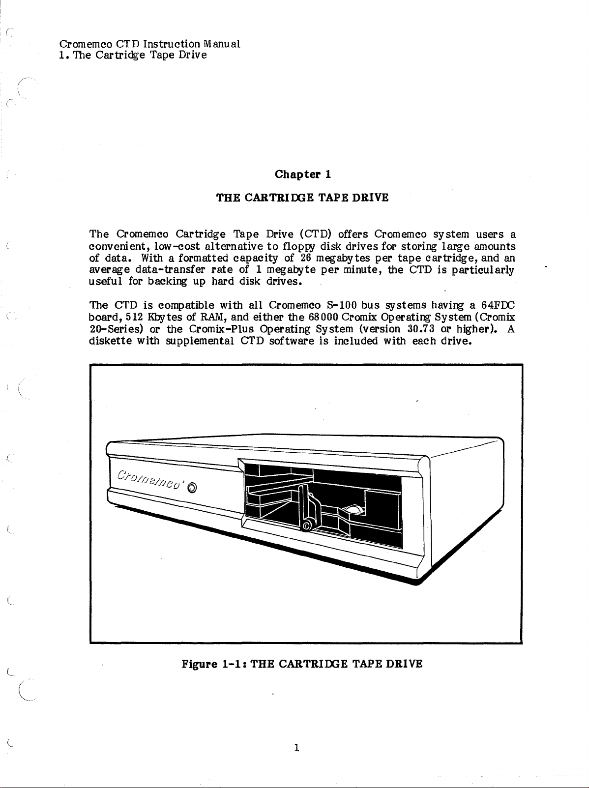
The Cromemco Cartridge Tape Drive (CTD) offers Cromemco system
convenient,
data.
of
average
useful
CTD
The
board,
low-cost
With
a formatted
data-transfer
for backing up hard disk drives.
is
compatible with
512
Kbytes of
20-Series) or the Cromix-Plus Operating System (version
diskette
with supplemental CTD software
alternative
capacity
rate
of 1 megabyte
RAM,
and either
to
floppy disk drives for storing
of
26
megabytes per
per
minute, the
all
Cromemco S-100 bus systems having a 64FLC
the
68000 Crornix Operating System (Cromix
tape
CTD
large
cartridge,
is
particularly
30.73 or higher). A
is
included with each drive.
users
amounts
and an
a
J.
Figure
1-1:
THE CARTRIOOE TAPE DRIVE
1
Page 8
Cromemco
1.
The Cartridge Tape Drive
CTD
Instruction
Manual
INSTALLING
To
attach
listed
the
and
you
must
below. Before installing
64FDC
the
mod
do
not have a Revision D board with
be
modified (refer
the
board
level
THE
CTD
(the
CTD
to
yoursystem, follow
the
revision
number
to
letter
is
indicated
the
last
drive, check the revision and
is etched into
by
a
mod
section of this
with the CTD").
System One and System
Adding a CTD
to
model
100
CS1
(two 5-1/4" floppy drives) precludes
of another floppy disk drive. However, model
floppy drive and one hard disk drive) can
disk,
in
which
case
the
second floppy disk becomes Drive
support
back of the CTD connector.
Install
1.
the
CTD
Turn off
as
follows:
the
system, and remove
the
described in your system manual.
the
appropriate
label,
the
also
set
solder side of the board,
on
the
level 7 or higher, then
CS1H
both a
chapter,
and System 100 (one 5-1/4"
CTD
"Using the
and another floppy
B,
and plugs
upper and lower
of instructions
mod
level
solder side).
the
64FDC
64FOC
the
addition
into
rear
panels as
of
If
the
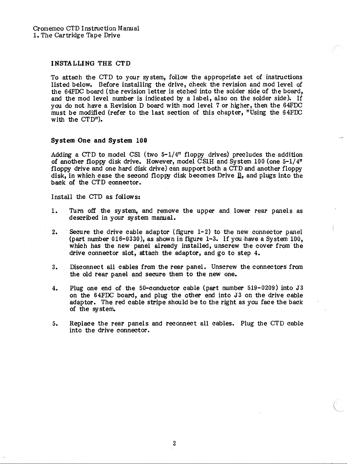
2.
secure
(part
which has
the
drive cable
number 016-0330),
the
drive connector
3. Disconnect
the old
rear
all
panel and
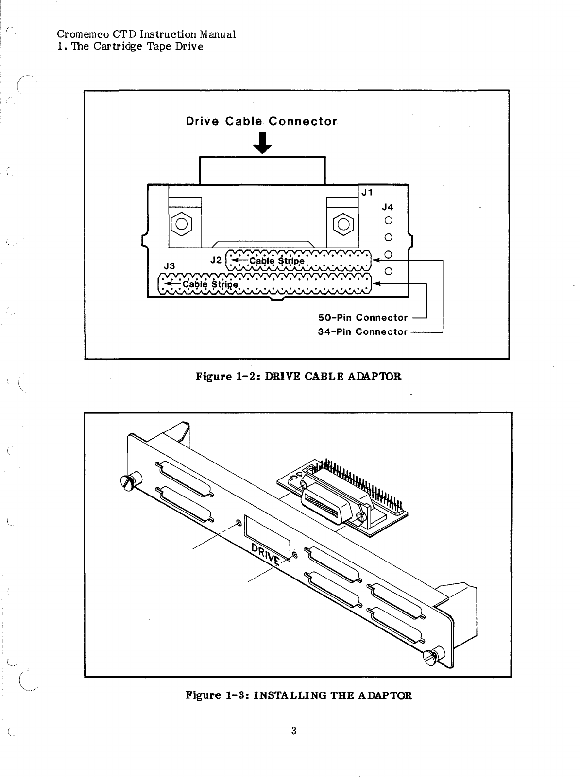
4. Plug one end of
on the
adaptor.
of
5. Replace
into
64FDC
The red cable
thesystem.
the
the
drive connector.
rear
adaptor
as
(figure
shown in figure 1-3.
new panel already
slot,
cables from
board, and plug
attach
secure
the
50-conductor
panels
the
the
rear
them
the
stripe
should
and reconnect
installed,
adaptor,
panel.
to
cable
other
betothe
1-2)
to
the
new connector panel
If
you
-have
a System 100,
unscrew
and go
to
the
step
cover from
4.
Unscrew the connectors from
the new one.
(part
end
all
number 519-0209) into J 3
into
J3
on
the
drive cable
right
cables.
as you
Plug
face
the
the
CTD
the
back
cable
2
Page 9
Cromemco CTD
1.
The
Cartridge
Instruction
Tape Drive
Manual
Drive
@
J3
("v,."".y..y...
·:-::::S!9~~A~1rip'e.
Cable
/
(,v'''''''''
J2
"-Cable
• A • A •A •A·• • A •
"'.V."'."'."'."'."'."'."'."' •
A'
Connector
p.
A. • A • A •A •
"-
..
??????
Stri e
'A'A'A'A'A'A'A'
©
••
A.
•"'."'."'.
A'
'A'A'A'A')
•
J1
...
-A-A-
Y'1
-
Figure
50-Pin
34-Pin
1-2:
DRIVE CABLE ADAPTOR
Connector
Connector
J4
0
0
0
0
)
-
Figure
1-3:
INSTALLING
THE
ADAPTOR
3
Page 10
Cromemco
1.
The Cartridge Tape Drive
CTD
Instruction Manual
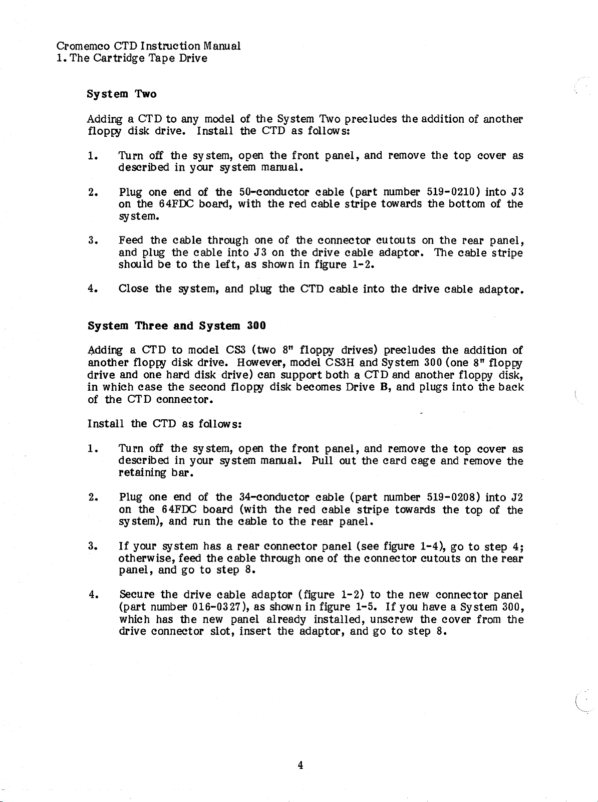
System Two
Adding a
CTDtoany model of
floppy disk drive.
1.
Turn off
the
Install
sy stem, open
the
the
CTD
System
the
front
as
follows:
described in your system manual.
2. Plug one end of
on the
64FDC
the
50-conductor
board, with
the
red
system.
3. Feed
and plug the
should
4. Close
System Three and System
.adding a CTD
the
cable through one of
cable
be
to
the
the
system, and plug the
to
model
into
left,
CS3
as
300
(two
J3
shown
the
on
the
in
CTD
8"
floppy drives) precludes
another floppy disk drive. However, model
drive and one hard disk drive) can
in
of
which
the
case
CTD
the
second floppy disk becomes Drive
connector.
support
Two
precludes the addition of another
panel,
cable
cable
connector
drive cable
figure
cable
CS3H
and remove
(part
stripe
towards
cutouts
adaptor.
1-2.
into
and System
the
top
cover as
number 519-0210) into
the
bottom of the
on
the
rear
The cable
the
drive cable adaptor.
the
addition of
300
(one 8" floppy
both a CTD and another floppy disk,
B,
and plugs
into
the
J3
panel,
stripe
back
Install
1.
the
CTD
Turn off
as
fallows:
the
system, open
the
front
described in your system manual. Pull out
retaining
bar.
2. Plug one end of the 34-conductor
3.
4.
on the
64FDC
system), and run
If
your system has a
otherwise, feed
panel,
secure
(part
and go
the
number 016-0327), as shown in figure 1-5.
which has
drive connector
board (with
the
cable
rear
the
cable
to
step
the
red
to
the
connector panel
through one of
8.
drive cable adaptor (figure
the
new panel already
slot,
insert
the
adaptor,
panel,
cable
(part
cable
rear
panel.
the
1-2)
installed,
and go
and remove
the
card
the
top
cage and remove the
number 519-0208) into J2
stripe
(see
connector
towards
the
figure 1-4), go
cutoutsonthe
to
the
new connector panel
If
you have a System 300,
top of the
unscrew the cover from
to
step
8.
cover as
to
step
4;
rear
the
4
Page 11
Cromemco
1.
The Cartridge Tape Drive
CTD
Instruction Manual
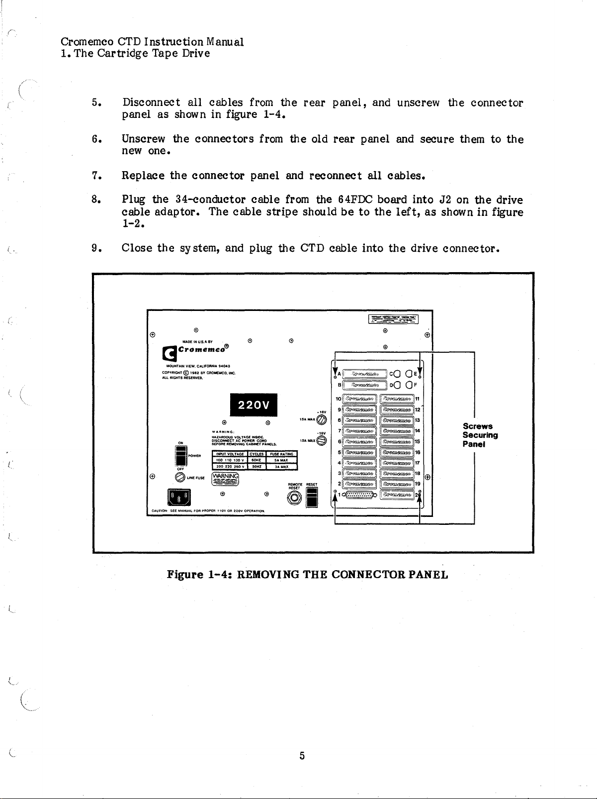
5. Disconnect
panel as shown in figure
all
cables
from
1-4.
the
rear
panel,
and unscrew the connector
6. Unscrew the
connectors
from
the
old
new one.
7. Replace
the
connector panel and reconnect
8. Plug the 34-conductor cable from the
cable
adaptor.
The cable
stripe
should
1-2.
9.
Close
the
system, and plug
[3
c-;:::~;:.c:o®
MOUNTAIN VIEW, C.....IFORHI
COPYRIGHT@
All..
RIGHTS RESEtWED.
i~w
0,"
~LINEFUSE
1982
BY CROMEMCO. INC.
..
...
94043
WARNING:
HAZAAOQUSVOL
TAGE INSlOE.
AC POWER COAO
DISCONNECT
BEFORE
REMOVING
CABW!T
INPUT VOLTAGE CYCLES
100 110
130V60HZ
200220260
v
PANELS.
the
CTD cable into
rear
panel and secure them to
all
cables.
64FDC
be
board into J2 on
to
the
left,
the
drive connector.
as
the
the
drive
showninfigure
Screws
Securing
Panel
CAUTION. see
•
Figure
MANUAL
FOR PROPER I lOY OR
1-4:
220V
OPERATION.
REMOVING
THE
5
CONNECTOR PANEL
Page 12
Cromemco
1.
The Cartridge Tape Drive
CTD
Instruction Manual
Ci/
110
CONNECTORS
S'-
B
c!\
?
cOO
?
DO
0 F
E
<;)
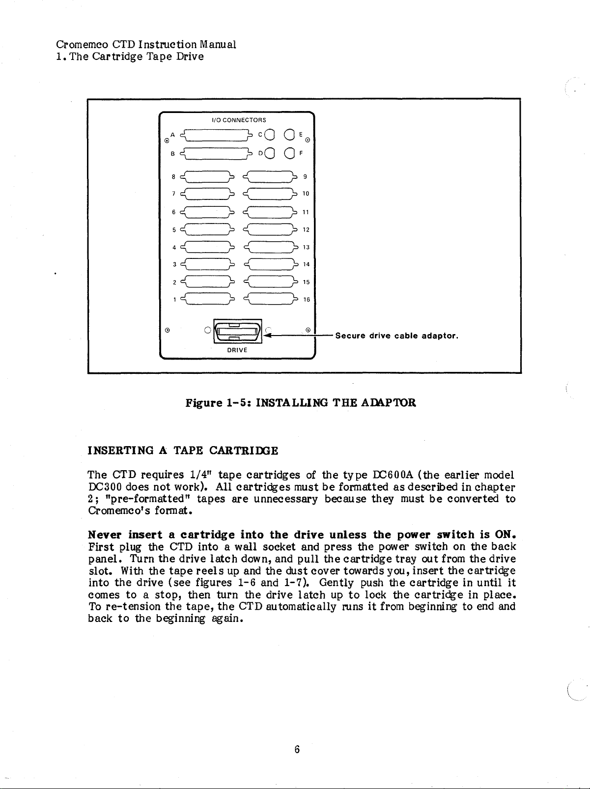
INSERTING A
ae:<
7
e:<
6e:<
5
e:<
4
e:<
3C=---.?
2
e:<
1
e:<
o
TAPE
o
Figure
CARTRIOOE
?e:<
?
e:<
?e:<
?
e:<
?
e:<
e:<
?
e:<
?
e:<
~""'(~I-'
DRIVE
1-5:
INSTALLING THE ADl\PTOR
?9
?
10
?11
?
12
?
13
?
14
?
15
?
16
-.....;.-@-:---SecuredrivecableadaPtor.
The CTD requires 1/4"
DC300 does not work). All
2;
"pre-formatted"
Crom
emc0's format.
Never
First
panel.
slot.
into
comes
To
back
insertacartridge
plug the
Turn
With
the
drive
toastop,
re-tension
to
the beginning again.
the
the
the
CTD
drive
tape
(see
then turn the drive
tape,
tape
tapes
into a wall socket and
latch
reels
figures
the
cartridges
cartridges
are
unnecessary because they must
into
up
1-6
CTD automatically runsitfrom beginning to end and
the
down, and
and the dust cover towards you,
and 1-7). Gently push the
of the
must
drive
pull
latch
6
type
LC600A
be
formattedasdescribed in
unless
press
the
up
the
the power switch on the back
cartridge
to
lock
(the
be
power
tray
out from the drive
insert
cartridge
the
cartridge
earlier
chapter
converted to
switch
the
is
cartridge
in until
in
model
ON.
it
place.
Page 13

Cromemco
1.
The Cartridge Tape Drive
CTD
The
Write-Protect
The
write-protect
sensitive
to
SAFE,
Instmction
data
from being
the
tape
arrow points in the opposite direction,
erased.
Manual
Switch
switch
can
be
on
the
altered
read,
tape
cartridge
or destroyed.
(see
figure
If
the arrow on the switch points
butitcannot be written
the
tape
can
be read,
1-7)
can prevent
to
or erased. If
written
to,
the
and
Figure
1-6:
INSERTING A TAPE CARTRIDGE
7
Page 14

Cromemco
1.
The
Cartridge
CTD
Instruction Manual
Tape Drive
r-
Dust
Cover
Write-Protect
Switch
--ff'9i-i
Figure
1-'1: THE DC600A CARTRIDGE _
8
Page 15

Cromemco
1.
The
Cartridge
USING THE 64FOC WITH THE CTD
A
modified
a Rev.
following procedure; for
modification.
CTD
64FDC
Instroction
Manual
Tape Drive
that
is
not a revision D board with
to
support the CTD. For a Rev. B board
D board at
mod
levels
earlier
3 through 6, do only
revision/mod-level combinations, do
mod
level
at
7 or higher must
mod
level
steps
12
be
9 or higher, or
and
13
of
the
the
entire
Note:
Position
See figure
1.
2.
3.
4.
5.
This modification shouldbedone only
distributor
the
1-8
Install
Install
Install
Install
Cut
trace
board with
Jumper A from J2 pin 2
Jumper B from
Jumper C from
Jumper D from
or
service
the
for
the
locations of
at
location E from IC40 pin 4
facility.
solder side up and
all
J3
pin 8
RN12
RN12
pin 6
Pin 5
to
to
by
an
the
solder-side
J3
pin 22.
IC11 pin
to
IC52 pin 9.
to
IC52 pin 14.
to
authorized Cromemco
dealer,
edge connector towards you.
cuts
and jumpers
5.
the
feed-through hole
next
to
IC40 pins 12 and 13.
the
Turn
board over so
is towards you. See figure
6.
f
,
7.
Install
Install
Jumper F from
Jumper G from IC15 pin 5
that
1-9
ICl1
the
component sideisup and
for
the
locations of
pin 2
to
ICll
to
IC27 pin 24.
pin 4.
the
edge
connector
all
component-side jumpers.
8.
9.
10.
11.
Install
Install
Install
Install
Jumper H from IC15 pin 6
Jumper I from IC15 pin 6
Jumper J from IC20 pin 3
Jumper K from IC52 pin 8
to
IC52 pin 9.
to
IC20 pin 4.
to
IC26 pin 29.
to
the
feed-through hole below IC30 pin
10.
12.
trace
between
the
feedthrough holes at jumper option
Next
to
IC6,
cut
the
block "B".
13.
Install
Jumper L from
the
top
hole
of
jumper option block "B"toIC42 pin
2.
This completes
and checkout procedures
l
the
modificationstothe
to
verify
64FDC
proper
9
board. Follow normal
operation.
installation
Page 16

Cromemco
1.
The Cartridge Tape Drive
CTD
Instruction
Manual
co
~
••
~
::s
bD
00
I
Go)
...
10
Page 17

Cromemco
1.
The Cartridge Tape Drive
CTD
Instruction
Manual
••
=
I
1'"'4
QJ
...
::s
bD
...
Iil:oI
11
Page 18

Cromemco
CTD
Instmction
Manual
12
Page 19

Cromemco
2. Using
CTD
Instruction Manual
the
CTD Software
Chapter 2
USING THE
This
and
chapter
transfer
describes
files
to
how
to load
and from the CTD. These procedures
Cromix-Plus and Cromix 20-Series Operating Systems, so follow the
set
of instruction
CROMIX-PLUS OPERATING SYSTEM
If
you have the Cromix-Plus Operating System (version 30.73 or higher), do
load
the
software from
not
support the CTD).
the
CTD driver,
Igen/sysdef
Initializing
tape
Every
cartridge
users) before
listed
use
file, and
below.
the
CTD diskette
If
your
the
Screen editor to add
generate
a Tape Cartridge
must
be
initialized with the
it
can
be
used
to
the
current
a new
store
CTD
SOFTWARE
CTD
software,
initializeatape
are
different for the
appropriate
(earlier
versions of Cromix-Plus do
cromix.sys program does not include
tflop
to
line
"BDEV
cromix.sys.
data.
The
Inittape
general
utility
(for privileged
command format
cartridge,
not
0411in
the
is
inittape
l
If
the
Inittape
for them as the program executes.
in
chapter
•
inittape
Inittape
Press:
CTRL-C
Warning:
Do
Device name?
[[-vf]
parameters
[-s
#[,#]
are
devname]
not
placed in
the
command, you will be prompted
Insertacartridge
1,
and
enter
(user entries
are
boldfaced):
version 30.xx
RETURN
to
abort program
inittape
to supply
will destroy
default
all
disk data
answers
you wish retension delay of 180 seconds
ftcd
into
(YIN)
the
drive,asdescribed
<N>?
RETURN
13
Page 20

Cromemco
2. Using
The CTD retensions each
it
over
CTD
Instmction
the
CTD
Software
Fonnatting
First
Last
stream (0-5.)?
stream
(0-5.)?
lni tializing stream 0
Initializing stream 5
from beginning
(the
drive
to
light
Manual
<0>
<5.>
tape
end and back
is
out), press
RETURN
RETURN
when
to
RETURN
it
is
first
placed in
the beginning.
for
the
the
drive
If
the retension cycle
first
prompt.
by
mnning
is
Next,
of any
Inittape
tape
device name while the
and a repeated prompt for
lnittape
may
prompts for the
want
asks
for
the
drive connected
tape
first
to
format a portion of a
device name of
to
your system, such as
is
being retensioned
the
device name.
and
last
streamtobe
tape
(e.g.,
the
tape
when
drive. Use
fted
results
fonnatted.
in a device open error
or
the
ftab.
On
a single stream has
device name
occasion, you
errors).
If
Inittape
prompts
is
are
taken from
called
with a device name argument,
the
command
line.
If
no options are specified, all
the
responses to
streams are formatted. The available options are defined as follows:
-f
-8
-y
For example,
This option defeats
is
being retensioned
If
a single number (0 through
the
tape
results
retension
delay,
but
in a device open error.
5)
follows the
-8
option, only
stream is formatted; a pair of numbers separated
range of streams
The "verbose" option provides progress
to
fonnat streams 1 through 3 in verbose mode,
to
be
fonnatted.
reports
usingitWhile
the
by
a comma specifies a
as formatting proceeds.
enter:
Entering a
frequent
the
above
the
tape
specified
if
inittape
Please
Device name:
First
Last
stream:
stream:
-y
wait for
-8
tape
ftcd
1.
3.
1,3
Initializing stream 1
Initializing stream 2
Initializing stream 3
if
fted
retension time (180 seconds)
14
Page 21

Cromemco
2.
Using
CTD
Instroction
the
CTD Software
Manual
Backing
The Rcopy
file
The
Rcopy is primarily intended for dumping hard disk data onto a
Up
utility
or
block device.
general
!'Copy
command format is:
[-b
Files
on
Tape
(for privileged users) copies a fileorblock devicetoanother
if]
[-e
if]
[-d
if]
[-1
if][
-s
if]
[-fcptv]
arguments
tape
cartridge
or another hard disk. Data saved with Ftback (68000 Cromix version 20.65)
cannot
directories,
of
input or standard
-b
-e
be
restored
Rcopy must
the
Tar
utility.
The number following
with Rcopy.
be
A
II
_II
in
output.
used
in
placeofa
The available options
-b
is the.!iJ:a1. block of
without this option, reading begins
data,
copying specific
table
(block 19).
The number following
such as a hard disk label (block0)or
-e
is
the
without this option, reading
output
device
is
reached first).
To
store
and
retrieve
individual
files
conjunction with version 20.08 (or higher)
fileordevice name indicates
are
defined
the
i.nmlldevicetobe
at
block
o.
This optionisuseful
as
the
standard
follows:
alternate
last. block of
stops
at
the
the
last
block (unless
i.nmll devicetobe
the
end of
or
read;
for
track
read;
the
-d
-s
-1
-f
-c
-p
-t
The number following
written;
without
The number following
The number following -1 is
CTD
is
Without
all
other
used
for input or
this
option,
files/devices).
-d
is
the
.1itsi block of
this
option, writing begins at block
-8
is
the
the
buffer is
A buffer of
total
the
length of
output,aunit
number
is
10
units (170K for
510K
(-I
the
of
blocks
the
I/O buffer in
17K;
30)
outDUt device
O.
to
be
otherwise a
the
CTD and
yields
an optimum speed
read.
units.
unit
to
If
is 1K.
10K
be
the
for
of 2 Mbytes/minute when copying between a CTD and a hard disk. This
is
option
When
Mter
optiontoverify that
than the CTD,
ignored when copying between uniform
output
copying
is
toafile,
to
or from the CTD,
the
the
-Y
option
this
input
option overwrites
repeat
and
output
copies
and verifies on one
the
are
This option reduces copying time when both input and
Cromix-Plus flopP.l disks
or
double-density). In
regardless
of
the
-1
This option provides a
(large
this
setting.
terse
or small,
case
progress
the
buffer size
single-
report
(UNIX)
the
floppy disks.
existing
data.
Rcopy command with
identical.
For devices other
pass.
output
devices
or double-sided,
equals
the
cylinder size,
as copying proceeds.
the
-c
are
single-
-y
For devices other than the CTD, this option compares
the
with
input
and sends an
error
message
if
they
the
copied output
are
not
the
same.
15
Page 22

Cromemco
2.
Using
CTO
Instruction Manual
the
CTO Software
Verification of
the
-c
option.
Examples
When
the
and
A):
To
If
copying to an
disk
label
19
on floppy disk files
#
reopy
#
reopy
restore
#
reopy
#
reopy
the
CTOisthe
(block
-t
-t
these
-t
-t
Rcopy commands.
copy,
enter:
cartridge
entire
0)
-s
1
Idev/stdO
-b
19
blocks in
tapes
hard disk
or
alternate
label
andalttable,
-s1/dev/stdO
the
event of a hard disk
-s1/dev/fda/label
-d
19
-s
1
/dev/fda/alttable
input or
To
output
device, copying and verifying requires
copy partition
requires
(std31
track
a second execution of Rcopy with
or
std63),
table
enter
/dev/fda/label
/dev/fda/alttable
Idev/stdO
std3
to
floppy
be
sure
nottooverwrite
(block 19).
To
(for an 811diskette
crash,
enter:
Idev/stdO
tape,
and then verify the
save blocks 0
in drive
separate
#
Since
for
To
create
the
reopy
#
reopy
the
second
-t
/dev/std3
-te
/dev/std3
tapeisrewound
pass.
and verify a Tar archive of directory
enter:
#
tar
Tar
#
tar
writes
-cvf
-evf-lusr/data
directory
-
option). Rcopy takes
and
writesitto
the
selected).
after
/usr/data
lusr/data
the
data
tape.
In
/dev/fled
/dev/fted
each Rcopy command,itis
/usr/data
I
reopy-Idev/fted
I
reopy
to
-c-/dev/fted
the
standard
from standard input
this
case,
Tar
issues
the
output
(the
progress
correctly
on a
(the
dash<
tape
after
positioned
cartridge,
the
dash for the input file),
reports
(v
option
f
16
Page 23

Cromemco
2.
Using
To
enter:
To
To
CTD
Instruction Manual
the
CTD Software
restore
#
reopy
list
the
#
reopy
dump
#
the
reopy
a specific file or directory from a
/dev
/fted
contents
/dev/fted
contents
/dev/fted
of a
of a
- I
tar
tape
created
- I
tar
tape
created
- I dump
-xvf
-tvf
-
filename
with the Tar
-
by
tape
Rco~
created
utility,
alone,
with the Tar
enter:
enter:
utility,
Sample BackUp Command
The following
root
device (and
approximately 6:30
file
to
initiate the
%find
_day % (Friday)
timelmatch
testinp
if
-err
-df
goto wrong_day
command
all
mounted devices) onto a
pm.
process.
-c
fri
>/usr/mtch.tmp
/usr/mtch.tmp 1
File
file, named
Include
the
goto find_time
%wrong_day
%
sleep
goto
$find_time % (6:30
timelmatch
testinp
if
21600
find_day
-c
-df
/usr/mtch.tmp 1
-err
goto wrong_time
18:3?:??
try
>/usr/mtch.tmp
goto back_time
%wrong_time
sleep
goto
300
find_time
% wait 5
autobak.cmd,
tape
line
"autobak&" in
again in 6 hours
pm)
minu
tes
automatically backs up the
cartridge
the
every Friday at
/etc/startup.cmd
%baCk_time %
mode
-pa
initiate
tape
backup
echo Preparing weekly backUp
d /
tar
-cf
- / I rcopy
if
-err
goto err1
echo Weekly backup
l
-t
-1
written,
30-/dev/ftcd
ready to verify.
17
Page 24

Cromemco
2. Using
tar
if
echo Weekly backup verified. Please change
mode
goto wrong_day % begin
%errl
echo Weekly backUp failed during
mode pa
goto wrong_day % begin
%err2
echo Weekly backup failed during verify pass.
mode pa
goto wrong_day %begin
CTD
Instroction Manual
the
CTD Software
-cf
- 1 I
-err
goto err2
pa
!'Copy
ct
-1
30
-
Idev/ftcd
cycle
write
cycle
cycle
again
to
again
again
tape
tape.
and
reset
clock.
CROMIX
Loading
To
load
a privileged user, mount
20-SERIES
the
CTD
the
CTD
OPERATING SYSTEM
Software
software,
a
insert
file
to
the
CTD disketteina floppy disk drive. As
the
diskette,
The command sequenceisshown below for
(use
sfda
I
create
:I
mount
I d
la
I
install
If
you have
If
you do
Igen_20.65
program,
as
I d
Igen
I
cptree
I unmount
#
crogen68
for the
68000
not
follows:
la
fda
5-1/4"
1a
diskette):
Creates
Mounts
Makes
Loads the
Cromix version 20.65 or higher, unmount and save
have
directory
68000
Cromix version 20.65 or higher, then copy
from
the
diskette,
Makes
-f
la/gen_20.65
fda
Overwrites
•
Unmounts the
Creates
the
8"
the file 1
fa
to
la
the
CTD
and
Igen
Igen
a new
and ron the
diskette
-mounted in Drive A
a.
the
diskette
current
directory.
software.
generate
the
current
with
Igen_20.65.
diskette
cromix.sys
Install
in Drive A.
the
a new
directory.
in Drive
program.
command.
diskette.
the
new
cromix.sys
A.
Answer
the
Crogen68 prompts for your
documentation), and
cromix.
diskette
If
the sy stem boots properly, copy the
and
root
test
the
new operating system by giving
directory. Store the
particular
CTD
18
system (refer to your Cromix
the
command
cromix.sy
diskette
in a
s file
safe
to
place.
boot
your boot
Page 25

Cromemco
2.
Using
CTD
Instruction
the
CTD Software
Manual
Initializing
Each
Insert
tape
a
a
Tape
cartridge
cartridge
Cartridge
must
into
the
be
initialized beforeitcan
drive,
as
described
in
chapter
be
used
1,
and
to
store
enter
data.
(as
a
privileged user):
i
ftinit
The following messages should appear:
Ftinit
Press: CTRL-C
<.
.
Warning: FTINIT
This program will
When
other
using version 00.11 of
processes (inclUding Flush) should
disk is
the
tape
The drive name
to
the
prompts
version xx.yy
accessed
could
Idev
directory
appear
to
abort
can
program
destroy
initializeatape
the
Ftinit
while version 00.11 of
be
selected.
"ftcd"
(major device number 7, minor device number 0) was added
(as
a block device)
after
the
above messages (recommended user
all
utility
tape
data
in
drive
be
Ftinit
by
the
ftcd
to
initializeatape
temporarily disabled.
is
running,
Install
cartridge,
the
wrong stream
If
a floppy
all
of
command. The following
replies
are
in
boldface):
Formatting:
Sector size (512/1024)? 1024
First
stream
Last
stream
First
segment (0-254)? 0
Last
segment
(0-5)?
(0-5)? 5
(0-
254)? 254
0
Initializing stream:
tape
A
5
(the
stream has
cartridge
stream number
255
Each segment has
sectors,
as
r
'--
shown below:
numbered 1
1
sector:
1 segment:
1 stream:
1
cartridge:
The
Ftinit
utility
single stream
has six streams, analogous
appears
on
the
segments, analogous
either
32
512-byte
to
17. Use of
512
bytes
16K
bytes
4,080 Kbytes
24,480 Kbytes
also
has
allows you
frequent
errors).
to
to
six floppy disks, numbered 0
to
screen as each streamisformatted). Each
to
floppy disk
sectors,
l-Kbyte
1K
bytes
17K
numbered 1to32, or
sectors
bytes
tracks,
maximizes
numbered °
17
1024-byte
tape
capacity,
to
254.
4,335 Kbytes
26,010 Kbytes
format a portion of a
tape
(e.g., when a
19
Page 26

Cromemco
2.
Using
CTD
Instroction Manual
the
CTD Software
Backing
The Ftback
file
It
is
Up
files
utility
on
(for
Tape
all
users)
transfers
files between
or block device. Systems ronning Ftback requireatleast
strongly recommended
that
the
following restrictions
using Ftback:
1.
Use a hard disk drive
disk,
you
can
copy a
partition.
However, with a WDI-II-controlled hard disk (which cannot
partitioned), you
can
as
the
tape
copy a
root device.
cartridge
tape
to
to
any partition other than
a second hard disk,
device.
Do
2.
3.
4.
5.
not run
Do
not
Run
Verify
the
comparing
The general command fonnat
other
pipe Tar
Check
the
tape
against
processes in
output
into
parallel
Ftback.
with Ftback.
utilitytoverify the integrity of
after
the
writing
original
by
reading back onto an empty partition and
partition.
is:
the
CTD
and any other
512
Kbytes of
be
observed when
With
an STOC-controlled hard
but
nottothe
the
disk you wish to copy.
the
RAM.
root
be
root
ftback
Ftback reads and
-Ii
input} -{o output} -[{bdes} block]
writes
data
from one device
to
bytes), and is primarily intended for dumping hard
cartridge.
(hexadecimal),
Ftback
or until
whichever occurs
output
capacities
rewound
Where possible, Ftback skips blocks with
locations of
i The device name following
Numeric arguments
"0"
(octal)
rons
until
the
either
the end of the input or
number of blocks specified
first.
or
For
are
"k"
the
device can accommodate
of
the
after
input and
each Ftback command.
the
bad blocks. The available options are defined as follows:
output
assumed
to
be
decimal unless they end in "h"
(units of 1024).
output
by
the
-s
or
-s
and
-e
options, Ftback verifies
the
specified number of blocks, otherwise
devices
are
not
non-fatal
-i
is
the
source of
the
names must begin with /deY). Without this option,
standard
o The device name following
input.
-0
is
the
destination of
names must begin with /deY). Without this option,
standard
output.
-{I
bytes}
another
disk
-e
in
block
data
device
has
options has been
compared. The
I/O
errors,
datatobe
the
the
copied
the
dataiswritten
units
onto
been
(512
a
tape
reached,
read,
that
tape
and
reports
copied (device
data
data
source
(device
the
the
is
the
is
to
20
Page 27

Cromemco
2.
Using
CTD
Instroction
the
CTD Software
Manual
b The block number following
read.
on
For
tapes
with 1024-byte
an even-numbered block. Without
-b
is
the
sectors,
~
block of
operationisfaster
this
option, reading beginsatblock
the
in:w.l1.
devicetobe
if
I/O
starts
O.
d The block number following
be
written.
Without this option, writing begins
e The block number following
read.
on
block (unless
\..
s The number following
this option,
I The number following
this option,
For
tapes
an
odd-numbered block. Without
with 1024-byte
the
end of
-s
all
of
the
-I
the
lengthiscalculated
amount of memory configured for Ftback. You should
the
buffer size.
must
be
smaller
If
you wanttouse
than
the
shown below).
-d
-e
the
output
is
the
total
blocks of
is
the
one
calculated
is
the
~
is
the.l.aa1. block of
sectors,
this
operationisfaster
option, reading
deviceisreached
number of blockstobe
the
input
length of
the
based on
the
-I
option,
by
block of the outDyt device
at
block
the
O.
in.D.u1.
devicetobe
stops
if
I/O ends
at
the
first).
device
are
I/O buffer in
the
tape
sector
let
the
buffer
Ftback (refer
read.
Ftback
to
read.
bytes.
size
the
Without
Without
size and
calculate
you
select
examples
to
last
the
Examples
To
copy a hard disk
block 0,
Ftback
enter:
i
ftback
reports
-i
/dev/hdl
the
calculated
(hdl)
number of blocks read and
Buffersize
21000
21000 blocks
When
are
the
input
important for efficient
"hdl1frequired two
data
to
a new
the
disk:
=192512
blocks
and
cartridge
read,
written,
output
cartridges,
from
starting
-0
from block0,toatape
/dev/ftcd
cartridge
buffersize immediately (in bytes), fallowed
written
blocks 0
blocks 0
devices have different
data
the
when
to
storage.
you
20999,
to
would
the
backup is complete.
"/dev/hdl"
20999,
In
the
use
block immediately
"/dev/ftcd",
capacities,
above example,ifbacking
the
-b
option
after
the
starting
sectorsize
the
block numbers
to
begin copying
last
one read from
at
by
the
=1024
up
i
ftback
-i
/dev/hd1
-0
/dev/ftcd
21
-b
21000
Page 28

Cromemco
2.
Using
For
for a second hard disk)
the
CTD
Instroction
the
CTD Software
an
STOC-controlled hard disk,
individual
I
ftback
partition
-i
Idev/std1
Manual
you wishtocopy. To copy partition
to
back up the
-0
use
device name
entire
Idev/ftcd
Idev/std31
drive; otherwise
std1
(or
Idev/std63
use
the
to
tape,
name of
enter:
MOVING
When
target
and
using a
disk's
the
size
IM.TA
BETWEEN HARD DISKS
tape
label
of the Cromix
following procedure
1.
2.
Initialize
If
you
do
the
not
enter:
I
patch
>d
20C
00020C:
•
•
and make a
and
3.
Copy blocks 1
bytes
20Dh
20Ch
note
are
through 20Fh):
to
move
(block
uses
target
know
0),
device
disk
the
Idev/std63
00 00
"00,"
to
8C
of
the
byte 20Eh
18
from
data
alternate
file
system
Idev/std63
(if
size
AU
first
the
between
track
(bytes
necessary).
of
the
Cromix file sy stem
...
four
bytes
is
"8C," and byte
tape
to
hard diskS,
and
20Ch
as
an example.
be
sure
partition
to
20Fh
to
tables
in block
on
the
preserve
displayed. As shown, bytes
the
hard disk (this
20Fh
is
"AD."
step
(block 19),
1).
The
target
disk,
20Ch
overwrites
the
I
ftback
or
I
rcopy
Block 0 contains
target
disk.
-i
Idev/ftcd
-t
-b
the
1
-e
source
-0
Idev/std63
18
-d
disk's
22
1
Idev/ftcd
label
-b
1
-d
Idev/std63
and should
1-e
18 (Cromix 20)
(Cromix-Plus)
not
be
copied
to
the
Page 29

Cromemco
2. Using
CTD
Instruction
the
CTD Software
Manual
4. Patch
follows:
5.
6. To
Copy
or
restore
bytes
#
>s
patch
20C
20Ch
through
/dev/std63
20Fh
00020C: 11 00 RETURN
00020D: 54
00020E:
00020F:
000210:
A3
9E
22
00
RETURN
8C
AO
•
RETURN
RETURN
>e
I
the
rest
of
the
tape
to
#
ftbaek
i
reopy
the
-i
-b
file
/dev/fted
20
-d
20
system of
with
the
hard disk:
-0
/dev/std63
/dev/fled
the
target
the
values obtained in
-b
20
/dev/std63
disk,
enter:
step
-d
20 (Cromix 20)
(Cromix-Plus)
2,
as
if
eheck
If
the
source disk of
reports
(
illegal
-s
std63
the
dataislarger
block numbers, and
than
the
files
using those blocks
target
disk,
the
will
Check
be
incomplete.
utility
23
Page 30

Cromemco
CTD
Instroction
Manual
24
Page 31

Cromemco
A. Rcopy Error Messages
CTD
Instmction
Manual
RCOPY ERROR MESSAGES
This following error messages
Write
on
floppy
tape
instead).
You
cannot
verify
the
-c
Verify and
The
-v
Bad
argument
You
probably entered an
use
the
-v
option when
the
data
copied
option (compare mode).
Compare
and
-c
options are mutually exclusive.
for
to
options
option
or from a
illegal
may
cannot
cannot
x.
Appendix
be encountered when
be
copyi~
tape,
number for
A
verified.
to or from a
issue a second HeoW command with
both
be
selected.
the
option indicated.
usi~
(Use
the Rcopy
the
compare
tape
utility.
option
cartridge.
To
File
xxxxxx
The named input or
Using
You
File
The
File
The indicated file does not
STDOUTasoutputisincompatible
cannot
xxxxxx
-f
option must
xxxxxx
Device
not
use
already
should
xxxxxx
an
output
the
-v
be
should
ordinary
option when using
exists.
used to overwrite an
exist
not
or
block
fileisillegal.
to
be
compared.
exist
be
(the
mounted.
25
device
with
Heopy
specified pathname
file.
the
verify
with
pipes.
existi~
file.
option
may
selected.
be incorrect).
Page 32

Cromemco
CTD
Instroction
A. Rcopy Error Messages
be
Files cannot
copied to or from a mounted device.
Manual
Not enough memory for buffer
The buffer size specified with
Cannot
When
the
allocate
using
the
-y
size specified
both buffers.
and
-e
options,
by
the -1 option.
the
of
xxxxxx
-1
option exceeds
the
required buffer sizeisactually double
bytes.
the
available memory.
26
Page 33

Cromemco
B.
Ftinit
CTD
Instmction Manual
and
Ftback Error Messages
Appendix B
FTINIT
AND
FTBACK
ERROR
MESSAGES
This appendix describes the error messages that you might encounter while using
the Ftinit and Ftback
FTINIT
Error
An error occurred when Ftinit tried to seek to
Full
ERROR
seeking
track
Stream
to
buffer
x,
Segment
Ftinit wrote less than the
stream
x.
The
documentation under
of
characters
actually written
utilities.
MESSAGES
segment
the
first
segment of a stream.
not
status
written
y,
zx
(sIb
n)
Status
minimum
zx,
Characters
written
n number of characters
is a hexadecimal code described
w
to
segment y of
in
your Cromix
floPW disk error messages (write operations). The number
is
given
by
w.
FTBACK
The file name
l
standard output.
ERROR
If_If
MESSAGES
appearing
in
Ftback's messages
refers
to standard input or
Argument missing
One
of Ftback's options was specified without the necessary numeric argument.
'B'
or
'n'
argument
The argument for the
exceeds
-b
or
file
size
-d
option exceeds the
maximum
block
number
of the
input or output file/device.
Cannot
The attempt to find a specified block number returned
position
file
27
an
error.
Page 34

Cromemco
B.
Ftinit and Ftback Error Messages
'E'
CTD
Instroction Manual
or'S'
argument
exceeds
input
file
size
The arguments for the
input file/device.
pipe,
'E'
The arguments for the
output file/device.
a pipe,
E
Both the
file/device, and cannot be used together.
Floppy
Currently Ftback does not support I/O between two flopP.l
Floppy
no
check is made.
or'S'
argument
no
check is made.
andSoptions
-e
and
tape
tape
device
read
Unit 0, Stream 0, Segment 6,
I/O
error
on
input
input:
output:
-s
or
-e
option exceeds the
If
the file/device does
exceeds
-s
or
If
the file/device does not have a specified size, such as
cannot
-s
options designate
cannot
output
-e
option exceeds the
be
used
be
error
Sector
"/dev/ftcd",
"/dev/null",
together
used
error
error
not
file
size
the
for
both
1,
Status
between
between
maximum
have a specified size, such as a
maximum
ending block
input
and
0008,
blocks
blocks
block
block
number
output
tape
eRe
11544
204
number
number
drives.
error
to
to
of
the input
11544
204
of the
of the
An
I/O error message identifies the function (read or write) which encountered
the
error
file/device location (third line), and the block
and output file/device (fifth
number is the minor device number, and the
Cromix documentation under floppy disk error messages. The same
be
reported twiceifthe
Incorrect
An
error was returned
incorrect minor device number.
Incorrect
This message usually
conflicting options (e.g., a
(firstline),
floppy
I,
0,
B,
tape
E,
the
sector size
device
by
the floppy
D,
L,
results
-b
sector
and
location of the error (second line), the
number
sixth lines).
status
is
1024
bytes.
name
tape
open routines, usually due
orSargument
from
an incorrect numeric argument, or
argument larger than
28
location on both the input
On
the second line, the unit
code
an
is
described in your
-e
argument).
sector
from
to
may
an
two
Page 35

Cromemco
B.
Ftinit and Ftback Error Messages
CTD
Instmction
Manual
Not enough memory
Ftback is not configured
accommodate
memory
the
to
Ftback or specify a smaller I/O buffer with
size
for
I/O buffer
to
of
the
execute in
the
amount of
I/O buffer. Use the Config
memory
utility
the
which would
to
allocate
-1 option.
more
Unexpected argument
The
-v
option should not
V
option
Ftback uses
I
'.-
must
the
be
used
-v
option only if
be
with
followed
floppy
the
by
an argument.
tape
output
device
deviceisa
as
output
cartridge
tape.
29
Page 36

Page 37

LIMITED WARRANTY
(.(
Cromemco,
from
WhatIsCoveredByThis
During
used
set
forth
HowToObtain
You
service;
1.
2.
3.adescriptionofthe
4.
Shiporotherwise
D'ealer
View,
WhatIsNot
Cromemco
This
orbyimproper
and
ExclusionofLiability,
THIS
WARRANTIES,
WHERE
OF
REPAIRORREPLACEMENTASPROVIDED
DAMAGES
PERMIDEDBYLAW,
DAMAGES.
WARRANTY,ORADDITIONAL
ACCORDINGLY,
OF
AND
Inc.
("Cromemco")
the
dateofpurchase,
the
ninety
(90)
day
parts
any
partsorcomponents,
below.
Warranty
should
immediately
first
obtainareturn
Your
name,
the
return
proofofthe
from
whom
Ca.
94043.
authorization
notifyINWRITING
address,
dateofretail
return
you
and
problem,
the
purchased
CoveredByThis
does
not
warrant
warranty
insurance
THIS
CROMEMCODONOT
does
not
service.
charges
WARRANTYISIN
INCLUDING
SUCH
EXCLUSIONISALLOWED
PRODUCT.IFTHIS
FOR
THE
THE
AGENTS,
ADDITIONAL
FIRMWARE
ARE
applyifthe
This
incurredintransporting
BREACHOFANY
DAMAGES
LICENSED
warrants
subjecttothe
this
equipment
following
Warranty:
warranty
period
Cromemco
manufacturedbyCromemco,
Service:
your
authorization
telephone
number
purchase
product,
numberbycontacting
number,
and
transportation
the
product,
Warranty:
any
products,
product
productisnot
Damages,
LIEUOFALL
IMPLIED
PRODUCTISNOTINGOOD
DEALERS,
WARRANTIES
STATEMENTS
CONSTITUTE
components,orparts
has
been
warrantedtooperate
and
Other
OTHER
WARRANTIESOFMERCHANTABILITY
AND
EXPRESSORIMPLIED
FOR
PERSONAL
AND
WARRANTIES
ONLYBYA
against
defectsinmaterial
terms
and
conditions.
will,atits
DealerorCromemcoofproblems
and
insurance
you
should
damagedbyaccident,
the
producttoand
option,
which
the
Dealer
costs
contact
Cromemco
not
satisfactorily
from
repairorreplace
provetobe
from
prepaid,toyour
manufacturedbyCromemco.
abuse,
with
peripheralsorproducts
your
DealerorCromemco
Warranties:
WARRANTIES,
OTHERWISE
ABOVE.
EMPLOYEESOFCROMEMCO
BINDINGONCROMEMCO
WHETHER
CROMEMCO
INJURY,
ORALORWRIDEN
SEPARATE
WHETHER
LIMITEDINDURATIONTONINETY
WORKING
EVENIFCROMEMCO
AND
AGREEMENTONAN
ORDERASWARRANTED
SHALL
WARRANTY,
ABOUTORFOR
SHOULD
NOTBERELIED
and
workmanshiptothe
this
Cromemco
defective,
encountered
whom
Customer
misuse,
ORALORWRIDEN,
AND
FITNESS
NOTBELIABLE
INCLUDING
ARE
EXCEPT
"AS
during
you
purchased
Dealer.Ifyou
Support
modification,ormisapplication;bydamage
FORAPARTICULAR
DAMAGETOPROPERTY
HAS
BEEN
NOT
AUTHORIZEDTOMAKE
PRODUCTS
SIGNED
UPON.
IS"
BASIS.
original
purchaser
productorrepairorreplace
provided
the
productisreturnedtoyour
the
warranty
the
are
unabletoreceive
at:
Cromemco,
not
manufacturedbyCromemco.
are
not
EXPRESSORIMPLIED.
(90)
DAYS
ABOVE,
FOR
INCIDENTAL
ADVISEDOFTHE
WRIDEN
SOFTWARE,
periodinordertoobtain
product.
Then
Inc.,
coveredbythis
PURPOSE,
FROM
YOUR
SOLDORLICENSEDBYCROMEMCO.
STATEMENTS
TECHNICAL
for
ninety
(90)
with
new
Dealer
warranty
attachtothe
warranty
280
Bernardo
warranty.
THE
DATEOFPURCHASE
SOLE
AND/OR
AND,TOTHE
POSSIBILITYOFSUCH
MODIFICATIONSTOTHIS
product:
repair
from
Ave.,
Mountain
during
shipment;
Transportation
ANY
IMPLIED
ARE
EXCLUDED
REMEDY
FROMANOFFICER
SHALL
CONSEQUENTIAL
EXTENT
INFORMATION,
days
or
as
the
BE
LimitationonStatuteofLimitation
THIS
WARRANTY
IS
NOT
TRANSFERABLE.NOSUIT,
OR
IMPLIED
ALLOWING
OF
THIS
WARRANTY.
Other
Important
Some
statesdonot
so
the
above
is
prohibitedbyany
have
other
Rev.
0 6/14/84
AND
THE
STATUTEOFL1M,ITATIONS
WARRANTIESORFOR
SUCHALIMITATION;
Provisions:
allow
the
exclusionorlimitationofincidentalorconsequential
limitationorexclusion
federal,
state,ormunicipal
rights
which
vary
from
LITIGATION,ORACTION
OTHER
OTHERWISENOSUCH
may
statetostate.
and
Transferability:
CAUSE
not
applytoyou.
law
SHALL
RUN
SHALLBEBROUGHT
MORE
THAN
ACTION
This
warranty
which
cannotbepreempted.
CONCURRENTLY
BASEDONTHE
ONE
YEAR
AFTER
THE
SHALLBEBROUGHT
damagesorlimitationsonhow
shall
notbeapplicabletothe
This
warranty
WITH
ANY
ACCEPTANCE
ALLEGED
DATEOFPURCHASEINTHOSE
MORE
THAN
ONE
extent
gives
you
specific
PERIOD.
BREACHOFTHIS
YEAR
longanimplied
that
any
legal
THIS
JURISDICTIONS
AFTER
THE
warranty
provisionofthis
rights,
and
WARRANTY
WARRANTY
EXPIRATION
lasts,
warranty
you
may
also
 Loading...