

Page 1
Cromemco
3355A PRINTER
OPERATOR'S GUIDE
it
CROMEMCO, Inc.
280 Bernardo Avenue
Part no. 023
Mountain
-
6006 March 1980
View, CA 94043
Page 2

..
r
Page 3
Crom
e
m
3355A PRINTER
OPERATOR'S GUIDE
co
Part no
.
023-6006 March 1980
CROMEMCO, Inc.
280 Bernardo Avenue
Mountain
View, CA 94043
Page 4
PROPRIETARY NOTICE
The information and design disclosed herein were originated by
and are the property of Nippon Electric Company, Limited
(NEC). NEC reserves all patent, proprietary design, manufacturing, reproduction use, and sales rights thereto, and to any
article disclosed therein, except to the extent rights are
expressly granted to others. The foregoing does not apply to
vendor proprietary parts.
Specifications remain subject to change to allow the introduction of design improvements.
1
Copyright 1979 ©
NEC Information Systems, Inc.
5 Militia Drive
Lexington
Printed in U.S.A.
, MA 02173
V
Page 5
CHAPTER 1 INTRODUCTION
CONTENTS
Page
1.1 DESCRIPTION
1.2 SPECIFICATIONS
1.3 RELATED DOCUMENTS
CHAPTER 2 OPERATING INSTRUCTIONS
2.1 PRINTER CONTROLS .................................... 2-1
2.2 PAPER LOADING INSTRUCTIONS .......................... 2-3
2.2.1 Friction-Feed Paper Loading ................ 2-5
2.2.2 Pin-Feed Paper Loading ................... 2-5
2.2.3 Forms-Tractor Paper Loading ................ 2-6
2.3 SPINWRITER PREPARATION .............................. 2-6
2.4 TROUBLESHOOTING GUIDE ............................... 2-7
CHAPTER 3 MAINTENANCE AND REPLACEMENT PROCEDURES
3.1 MAINTAINING HIGH QUALITY PRINT ...................... 3-1
......................................... 1-1
...................................... 1-1
................................... 1-3
3.2 RIBBON CARTRIDGE REPLACEMENT ........................ 3-2
3.3 PRINT THIMBLE REPLACEMENT ........................... 3-2
3.4 FRICTION-FEED ATTACHMENT REMOVAL .................... 3-4
3.5 VERTICAL TYPE TRACTOR ASSEMBLY REMOVAL .............. 3-4
3.6 PIN-FEED PLATEN REMOVAL ............................. 3-5
3.7 FRICTION PLATEN REMOVAL ............................ 3-6
GLOSSARY .............................................Glossary-1
iii
Page 6
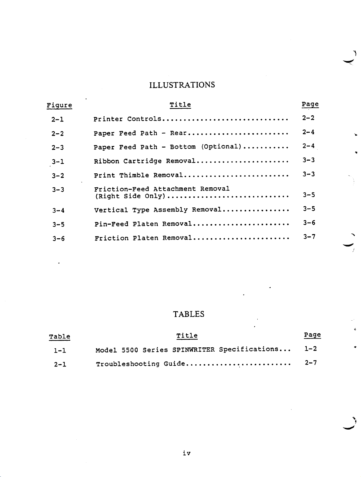
ILLUSTRATIONS
Figure
2-1
2-2
2-3
3-1
3-2
3-3
3-4
3-5
3-6
Title
Printer Controls ..............................
Paper Feed Path - Rear ........................
Paper Feed Path - Bottom (Optional)...........
Ribbon Cartridge Removal ......................
Print Thimble Removal .........................
Feed Attachment Removal
Friction
(Right Side Only
-
) .............................
Vertical Type Assembly Removal ................
Feed Platen Removal .......................
-
Pin
Friction Platen Removal .......................
Page
2-2
2-4
2-4
3-3
3-3
3-5
3-5
3-6
3-7
N
Table
1-1
2-1
TABLES
Title
Model 5500 Series SPINWRITER Specifications...
Troubleshooting Guide .......................
iv
Page
1-2
2-7
Page 7
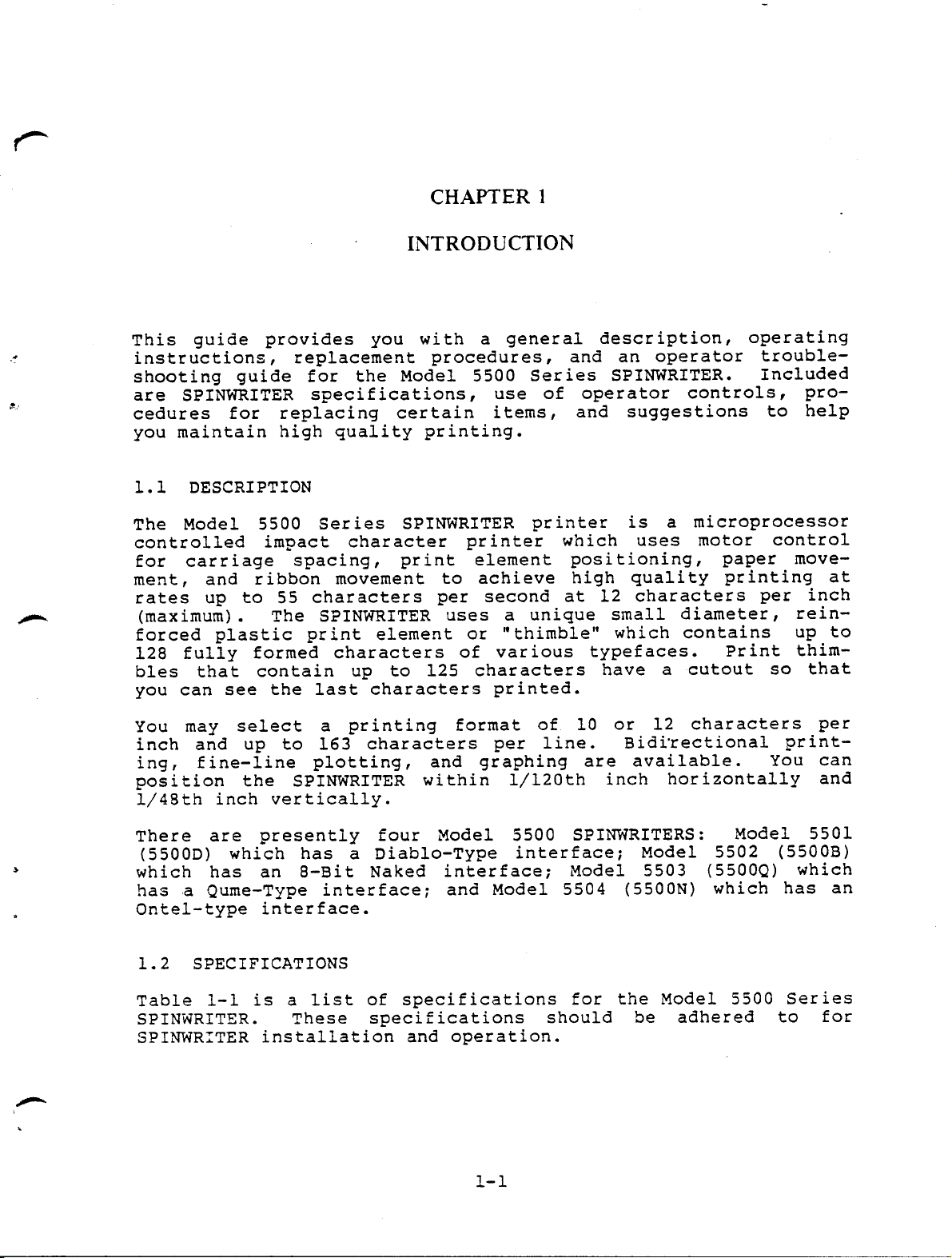
CHAPTER 1
INTRODUCTION
This guide provides you with a general description
and an operator trouble-
replacement procedures
instructions
shooting guide for the Model 5500 Series SPINWRITER
are SPINWRITER specifications
cedures for replacing certain items
you maintain high quality printing.
1.1 DESCRIPTION
The Model 5500 Series SPINWRITER printer is a microprocessor
controlled impact character printer which uses motor control
for carriage spacing
ment, and ribbon movement to achieve high quality printing at
rates up to 55 characters per second at 12 characters per inch
(maximum
forced plastic print element or "thimble
128 fully formed characters of various typefaces
bles that contain up to 125 characters have a cutout so that
you can see the last characters printed.
,
use of operator controls, pro-
,
print element positioning
,
The SPINWRITER uses a unique small diameter, rein-
).
,
and suggestions to help
,
,
which contains up to
"
.
operating
,
Included
.
paper move-
Print thim-
You may select a printing format of 10 or 12 characters per
Bidirectional print-
inch and up to 163 characters per line
line plotting
ing, fine
position the SPINWRITER within 1
1/48th inch vertically.
There are presently four Model 5500 SPINWRITERS
(5500D
which has an 8-Bit Naked interface
has a Qume-Type interface
Ontel-type interface.
1.2 SPECIFICATIONS
Table 1-1 is a list of specifications for the Model 5500 Series
SPINWRITER
SPINWRITER installation and operation.
-
which has a Diablo-Type interface
)
These specifications should be adhered to for
.
and graphing are available
,
120th inch horizontally and
/
and Model 5504
;
.
Model 5503
;
Model 5502
;
5500N
(
:
5500Q) which
(
which has an
)
You can
.
Model 5501
(
5500B)
Page 8
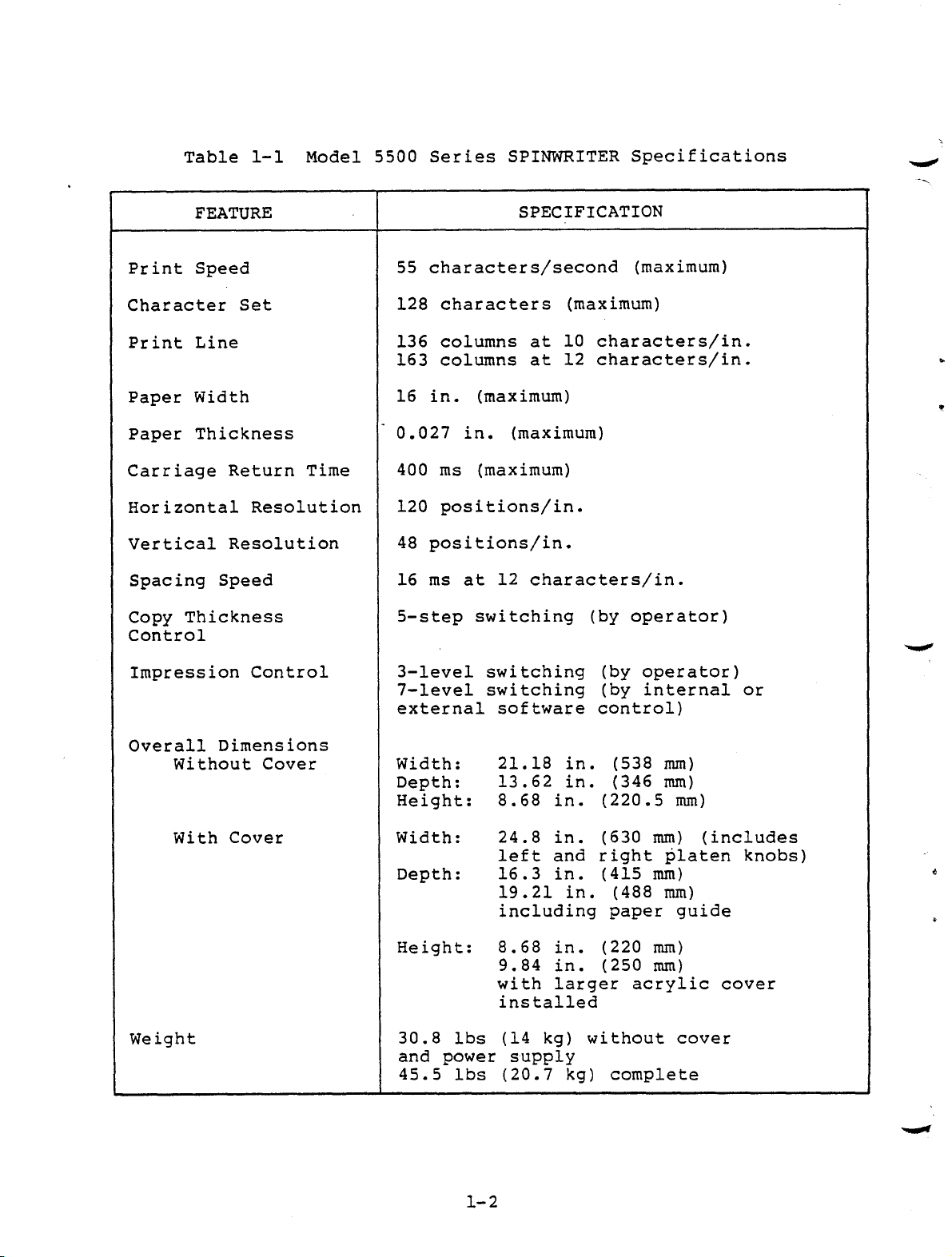
Table 1-1 Model 5500 Series SPINWRITER Specifications
FEATURE
Print Speed
Character Set
Print Line
Paper Width
Paper Thickness
Carriage Return Time
Horizontal Resolution
Vertical Resolution
Spacing Speed
Copy Thickness
Control
Impression Control
SPECIFICATION
55 characters
second (maximum)
/
128 characters (maximum)
136 columns at 10 characters/in.
163 columns at 12 characters/in.
16 in.(maximum)
0.027 in. (maximum)
400 ms(maximum)
120 positions/in.
48 positions/in.
16 ms at 12 characters/in.
5-step switching (by operator)
3-level switching
7-level switching
external software control)
by operator)
(
(
by internal or
Overall Dimensions
Without Cover
With Cover
Weight
Width
Depth: 13.62 in
Height: 8.68 in
:
21.18 in
. (
. (
220.5 mm)
. (
538 mm)
346 mm)
Width: 24.8 in. (630 mm
left and right platen knobs)
Depth: 16.3 in
19.21 in
including paper guide
Height: 8.68 in
9.84 in
with larger acrylic cover
installed
30
.
8 lbs
and power supply
45.5 lbs (20.7 kg) complete
14 kg) without cover
(
. (
. (
. (
. (
415 mm)
488 mm)
220 mm)
250 mm)
) (
includes
Page 9
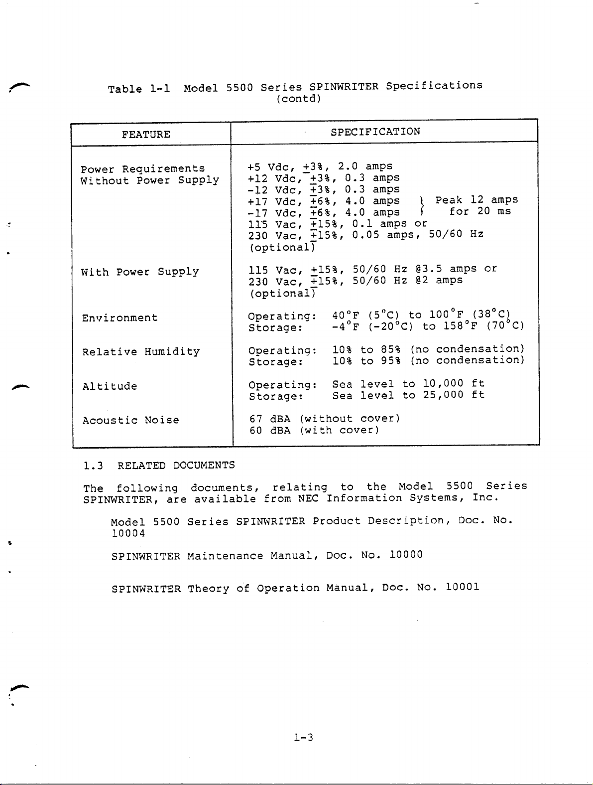
Table 1-1 Model 5500 Series SPINWRITER Specifications
(contd)
FEATURE
Power Requirements
Without Power Supply
+5 Vdc, +3%, 2.0 amps
+12 Vdc, +3%, 0.3 amps
SPECIFICATION
-12 Vdc, +3%, 0.3 amps
+17 Vdc, +6%, 4.0 amps Peak 12 amps
-17 Vdc, +6%, 4.0 amps for 20 ms
115 Vac, +15%, 0.1 amps or
230 Vac, +15%, 0.05 amps, 50/60 Hz
(optional)
With Power Supply
115 Vac, +15%, 50/60 Hz @3.5 amps or
230 Vac, +15%, 50/60 Hz @2 amps
(optional)
Environment
Operating: 40°F (5°C) to 100°F (38°C)
Storage: -4°F (-20°C) to 158°F (70°C)
Relative Humidity
Operating: 10% to 85% (no condensation)
Storage: 10% to 95% (no condensation)
r
Altitude
Operating: Sea level to 10,000 ft
Storage: Sea level to 25,000 ft
Acoustic Noise
67 dBA (without cover)
60 dBA (with cover)
1.3 RELATED DOCUMENTS
The following documents, relating to the Model 5500 Series
SPINWRITER, are available from NEC Information Systems, Inc.
Model 5500 Series SPINWRITER Product Description, Doc. No.
S
10004
SPINWRITER Maintenance Manual, Doc. No. 10000
SPINWRITER Theory of Operation Manual, Doc. No. 10001
Page 10

,..o,,
a
Page 11

CHAPTER 2
OPERATING INSTRUCTIONS
This chapter tells you how to operate the SPINWRITER. It
describes the printer controls, shows you how to load the
paper, and. gives you procedures for SPINWRITER operation.
2.1 PRINTER CONTROLS
Figure 2-1 illustrates the printer controls you will be using.
The numbers in the following paragraphs correspond to the num-
bers in the figure.
(1) Platen knobs. These allow the platen to be rotated
manually to insert paper and position it properly.
The right knob provides variable platen action; when
you push the knob in, the platen rolls freely in
either direction. You can change the position of the
writing line by using this variable platen function.
(2) Copy control lever. This lever moves the platen for-
ward or backward to compensate for different form
thicknesses (number of carbons). Place it all the way
forward for a single copy, and all the way rearward
for an original and seven carbon copies. Intermediate
positions provide for form thicknesses between these
two extremes. When printing on a form of several
copies with this lever moved toward the rear, you may
have to increase the print hammer intensity for optimum print quality by changing the impression control
switch (see Figure 2-1, 9).
0
(3) & (4) Pressure bail levers and pressure bail. The
pressure bail holds the paper against the platen for
optimum print quality and quietness. To insert paper,
pull the bail forward, away from the platen, by moving
one of the levers. When using a pin-feed platen or a
forms-tractor assembly, move the pressure bail forward
away from the platen. The pin-feed paper clamps or
the forms-tractor assembly hold the paper in the opti-
mum position for proper operation.
(5) Ribbon Selector Switch. The ribbon selector switch is
located under the top cover under the ribbon cartridge. Place the switch to the left for multi-strike
ribbons and to the right for red/black fabric ribbons. The switch can be used in either position for
the all-black fabric ribbon.
2-1
Page 12

4
BLACK OR MULTI- RED/BLACK
STRIKE R1880N RIBBON
Figure 2-1 Printer Controls
Page 13

(6) Silencer hood with combination scale
hoo
lowers the printer operation noise level. A long
d
and short hood are available
used with a forms
tractor assembly or a pin-feed
-
platen. When you raise the hood
vated which inhibits printing
must be closed for printing
visual indication of the print head position along the
typing line.
It is marked
acters per inch.
.
a short hood must be
;
a switch is acti-
,
therefore
;
The scale provides a
.
for both 10
The silencer
the hood
,
and 12 char-
(7) Top cover.
ward
.
It provides access to the printer mechanism
This cover raises easily
when it becomes necessary to replace a ribbon car-
tridge
hammer impression control switch
cover
therefore
(8) Paper release lever. In the forward position, this
lever releases tension on the paper, allowing it to be
repositioned or removed
printing on a friction
feeding of the paper
ON A PIN
ASSEMBLY.
(9) Impression control switch
locate
impression
to change the print thimble, or to change the
,
.
a switch is activated which inhibits printing;
,
be sure the cover is closed
,
Place the lever back when
.
feed platen to ensure proper
-
PLACE IT FORWARD WHEN PRINTING
.
-
FEED PLATEN OR WHEN USING A FORMS
.
This three position switch
under the top cover controls the printing
d
.
You may set this switch as follows:
L-low for minimum impact pressure which may be re-
quired for small typefaces
(
12 pitch); M-medium for
normal impact pressure which is required for most
single copy printing; H-high for maximum impact pres-
sure normally only for multiple copies. Poor print
quality may result from the incorrect setting of this
switch
also
,
in addition
,
too high an impression
,
setting may result in reduced font life.
by lifting up-
When you raise the
tightly.
-
TRACTOR
2.2 PAPER LOADING INSTRUCTIONS
The SPINWRITER has three different types of paper feed:
friction-feed, pin-feed, and vertical type tractor paper feed.
When loading paper, refer to the procedure below that applies
to the particular type of paper feed for your
machine
2-2 shows rear paper feed path. Figure 2-3 shows the paper
feed path for bottom feed.
NOTE
If you use a single sheet of paper in
the SPINWRITER, raise the paper guide
to deactivate the paper out switch.
2-3
. Figure
Page 14

Figure 2-2 Paper Feed Path - Rear
FEEDTHRU" I
Figure 2-3
Paper Feed
Path
2-4
- Bottom
(Optional)
Page 15

2.2.1 Friction-Feed Paper Loading
a. Raise paper guide and silencer hood.
b. Move the pressure bail. away from the platen.
c. Pull paper release lever forward.
d. Insert paper with printing surface down, as shown in
Figure 2-2.
e. Push paper release lever backward.
f. Push in and rotate the right knob of the platen to move
the paper.
g. Pull paper release lever forward.
h. Align the paper horizontally and vertically.
i. Push paper release lever backward.
j. Push pressure bail toward the platen.
k. Move paper to desired top of form position.
1. Adjust copy control lever. This lever should be in
extreme forward position for a single copy and adjusted
gradually toward rear as number of copies increases.
M. Lower the paper guide and silencer hood.
2.2.2 Pin-Feed Paper Loading
a. Raise paper guide and silencer hood.
b. Move the pressure bail away from the platen.
c. Pull paper release lever forward; it must REMAIN in the
FORWARD position.
d. Release the paper cutter bail from the platen.
e. Insert paper with printing surface down (for rear
feed), as shown in Figure 2-2.
f. Align paper feed holes with the left and right pin on
the platen; then lower the cutter bail to the platen.
g. Pull paper lightly toward the back to remove slack.
Page 16

h. Push in and rotate the right knob of the platen to
position the paper to the first line position.
i. Lower the paper guide and silencer hood.
2.2.3 Forms-Tractor Paper Loading
a. Raise paper guide, if rear feed is used, and raise the
silencer hood.
b. Move the pressure bail away from the platen.
c. Pull the paper release lever forward; it must REMAIN in
the FORWARD position.
d. Open tractor doors.
e. Insert paper with printing side down (for rear feed) as
shown in Figure 2-2.
f. Align paper feed holes with the pins of the left and
right tractor assemblies.
g. Close left tractor door.
h. Align right tractor with paper feed holes. You may
have to move the tractor assemblies. Release the
locking knobs and slide the assemblies to the desired
position.
i. Push in and rotate the right knob of the platen to
position the paper to the first line position.
Lower the paper guide and the silencer hood.
J
2.3 SPINWRITER PREPARATION
NOTE
Before
make
tioned to the extreme left or to the
extreme right.
a. Raise the top cover and check that the impression
control switch (see 2.1,9) and the ribbon selector
switch (see 2.1,5) are in the correct positions.
b. Make sure paper,
installed.
you apply power to the SPINWRITER,
sure that the carriage is not posi-
ribbon, and print thimble are properly
c. Close the cover.
2-6
Page 17

Connect the power cord to an ac outlet.
d.
Set
e.
the
to
2.4 TROUBLESHOOTING GUIDE
the POWER switch (located on rear of printer) to
ON position; observe that the carriage moves left
the first print position.
Table 2-1 lists several minor problems you may encounter, their
causes
, and the corrective action you can take. If, after
taking corrective action procedures, the machine is still not
functioning properly, call your service representative.
Table 2-1 Troubleshooting Guide
PROBLEM
INDICATION
Does not print
(Fan not running)
Does not print
Carriage does not
CAUSE
Power Source
Cover Open
CORRECTIVE
ACTION
Is SPINWRITER con-
nected to ac power?
is cover closed
tightly?
move
(Fan running)
Ribbon End
Check ribbon car-
tridge. If using a
multi-strike ribbon,
ensure that ribbon is
not at end (window on
cartridge will be
full).
Does not print
Carriage moves
Prints but car-
riage does not
move
Paper Out
Ribbon broken or
not installed
properly
Thimble broken or
not installed
properly
Obstruction in
path of carriage
Broken carriage
cable
2-7
Check paper supply.
Is paper loaded cor-
rectly?
Replace, if necessary.
Are ribbon and thimble
installed correctly?
Check for obstruction.
Call Service Repre-
sentative.
Page 18

Table 2-1 Troubleshooting Guide
contd)
(
PROBLEM
INDICATION
Paper tearing
Printing light
or not sharp
CAUSE
Paper not properly
loaded
Obstruction in paper
path
If using forms trac-
tors, too much
tension may exist
Paper release
may be engaged
lever
Ribbon worn, jammed
or broken
Ribbon or thimble
not installed
properly
Copy control lever
set incorrectly
Damaged platen or
thimble
CORRECTIVE
ACTION
Check paper loading
Adjust tractors
Check
lever
paper release
(
see 2.1,8).
Replace, if neces-
sary.
Check installation
Check position of copy
control level
Inspect for mars,
or abrasions.
/
and
Replace, if necessary.
Page 19

CHAPTER 3
MAINTENANCE AND REPLACEMENT PROCEDURES
This chapter suggests ways to help you maintain high quality
printing. It includes procedures for replacing ribbons,
thimbles, and other items.
3.1 MAINTAINING HIGH QUALITY PRINT
To ensure high print quality, proper attention should be given
to such items as various printer control settings, paper
quality, ribbon quality, etc. Here are several suggestions you
can use to maintain high print quality.
• Select the proper ribbon.... multi-strike ribbons give
you sharper impressions than a fabric ribbon. Dried or
malfunctioning ribbons will give you a faded print
image.
• Choose high quality paper to obtain the best print
image.... sharp, crisp characters and maximum
black-and-white contrast. Poor quality paper may
result in punctured paper or broken images.
• Select the proper copy control lever setting....all the
way forward for a single copy and moved rearward for
additional copies.
• Set the impression control switch for the best print
image .... low for small typefaces (12 pitch) , medium for
normal impact pressure, and high for large typefaces or
multiple copies.
• Set the space pitch setting so that it matches the
pitch of the thimble being used .... a mismatch will
result in cramped or widely spaced characters.
• Align paper correctly with enough tension so that it
does not tear or wrinkle.
• Keep the platen clean and free of mars and scratches.
•
Establish quality standards for different jobs...
similar jobs will be prepared in a similar manner and
require similar
quality.
Page 20

3.2 RIBBON CARTRIDGE REPLACEMENT
a. Turn POWER off and raise the top cover.
b. Hold the ribbon cartridge
press
place
the two locking
remove the cartridge upward
;
tabs
lightly;
which hold
at the same time
the cartridge in
see Figure 3-1).
(
c. Rotate the manual feed knob on the new cartridge in the
direction indicated
on the
ribbon.
by the arrow
to establish tension
d. Place the new ribbon cartridge over the mounting plate,
and insert the ribbon between the card holder and card
holder bracket.
e. Insert the ribbon in the ribbon sensor if a
see Figure 3-2).
multi
-
f. Press the
strike ribbon is used
ribbon cartridge downward until the locking
(
tabs engage.
NOTE
Rotate the manual feed knob on the
cartridge in the direction indicated by
the arrow to ensure proper seating.
g. Place tension
on the ribbon
(see c.).
h. Close the top cover and restore ac power.
3.3 PRINT THIMBLE REPLACEMENT
a. Turn POWER off and raise the cover.
b. Remove the ribbon cartridge (see 3.1).
c. Push hammer lock lever toward the platen
at the same time
, tilt
front.
at the center of the print thim-
d. Slide the lock piece
,
ble, horizontally and then to the upright position.
NOTE
When handling print thimble, hold it at
the base, to avoid possible damage to
the character type areas.
Figure 3-2);
(
the hammer cover toward the
r
Page 21

PLASTIC CARD HOLDER
LOCKING BRACKET
TABS
CARD RIBBON
HOLDER .CARTRIDGE
Figure 3-1 Ribbon Cartridge Removal
B
HAMMER
COVER
MULTI -STRIKE
RIBBON SENSOR
A
Figure 3-2 Print Thimble Removal
3-3
Page 22

e. Lift the print thimble upward from the carriage.
f. Place new print thimble in position aligning the square
(
hole with stud
Figure 3-2A).
NOTE
Be sure
has the same
that the replacement thimble
pitch (10 or 12) as the
original print thimble, and use light
pressure
on the base of the thimble to
ensure that it is seated fully downward.
Lay the lock piece flat and slide it until it is posi-
9
tioned as shown in Figure 3-2A.
h. Push the hammer and its cover into the locked position..
i. Install the ribbon cartridge.
j. Close the cover and restore ac power.
3.4 FRICTION-FEED ATTACHMENT REMOVAL
If this option is installed, it can be removed in the following
manner:
a. Turn POWER off
and raise
the top cover.
b. Move the pressure bail away from the platen.
c. Press the lock levers and simultaneously raise the
assembly upward and toward the rear of the printer as
shown in Figure 3-3.
d. Close the cover and restore ac power.
3.5 VERTICAL TYPE TRACTOR ASSEMBLY REMOVAL
If this option is installed, it can be removed as follows:
a. Turn POWER off and raise the top cover.
b. Move the pressure bail away from the platen.
c. Press the lock levers and raise the assembly upward and
toward the rear of the printer to remove it
3-4).
d. Close the top cover and restore ac power.
Figure
(
Page 23

LOCK
LEVER
FRICTION
FEED
ATTACHMENT
Figure 3-3 Friction-Feed Attachment Removal
(Right Side Only)
LOCKING "' 4 0
LEVER *d' •'^ ^' LEVER
Figure 3-4 Vertical Type Tractor Assembly Removal
WMW, - r' LOCKING
3
-5
Page 24

3.6 PIN-FEED PLATEN REMOVAL
If this option is installed, it can be removed as follows:
a. Turn POWER off and raise the top cover.
b. Move the pressure bail away from the platen.
c. Press the locking tabs and lift the platen from the
printer (Figure 3-5).
d. Insert the replacement platen into position aligning
the platen gear with the line-feed idle gear. Press
locking tabs, and press the platen downward until it
locks in place.
e. Close the top cover and restore ac power.
1
Figure 3-5 Pin-Feed Platen Removal
3.7 FRICTION PLATEN REMOVAL
a. Turn POWER off and raise the top cover.
b. Remove the friction-feed attachment or forms-tractor
assembly, if installed.
c. Press the locking tabs and lift the platen upward, out
of the printer (Figure 3-6).
d. Insert the replacement platen into position, aligning
the platen gear with the line-feed idle gear.
3-6
Page 25

NOTE
Because it
is possible to install the
platen backwards, ensure that the widest
gear
is on the right as the platen is
installed from the front.
e. Grasp the
press platen
platen knobs, press the locking tabs, and
downward until it locks into place.
f. Close the top cover and restore ac power.
LOCKING TAB(ON EACH END
OF PLATEN)
PLATEN
Figure 3-6 Friction Platen Removal
Page 26

GLOSSARY
Bidirectional - The machine prints while the print head
is moving either right or left.
Character set - A set or style of alphabetic, numeric,
and special characters (symbols).
Forms tractor unit - A device for aligning and feeding
continuous forms through the printer.
Space pitch - The number of characters per inch
printed.
0
Page 27

4
Page 28

 Loading...